FANUC Series 0i-MODEL F Plus. CONNECTION MANUAL (FUNCTION) - page 226
 

  Index      Manuals     FANUC Series 0i-MODEL F Plus. CONNECTION MANUAL (FUNCTION) B-64693EN-1/01


Search            copyright infringement  


Content      ..     224      225      226      227     ..


FANUC Series 0i-MODEL F Plus. CONNECTION MANUAL (FUNCTION) - page 226


10. SPINDLE SPEED FUNCTION


B-64693EN-1/01


- 1762 - 

Even in the spindle command synchronous control mode, the signals that need to be 
input/output or are used to control those functions (such as spindle orientation) directly 
specified from the PMC for the spindle control unit are provided independently for each 
spindle. 
For first spindle :  (DI:G0070 to G0073, DO:F0045 to F0048) 
For second spindle: (DI:G0074 to G0077, DO:F0049 to F0052) 
For third spindle :  (DI:G0204 to G0207, DO:F0168 to F0171) 
For fourth spindle : (DI:G0266 to G0269, DO:F0266 to F0269) 
When using the spindle command synchronous control function, exercise control on the 
spindle command synchronous control signals and also manipulate the signals for each 
spindle as required. 
(Such a signal state that the master spindle and slave spindle under spindle command 
synchronous control can make the same movement needs to be set.) 
 

NOTE 


In the spindle command synchronous control mode, the states of 
both the master spindle and slave spindle are checked. So, if 
spindle command synchronous control is specified in the Cs 
contouring control mode before the slave spindle is not activated 
yet, for example, the VRDY OFF alarm may be issued. Pay 
attention to control on the PMC signals for the slave spindle as 
well. 


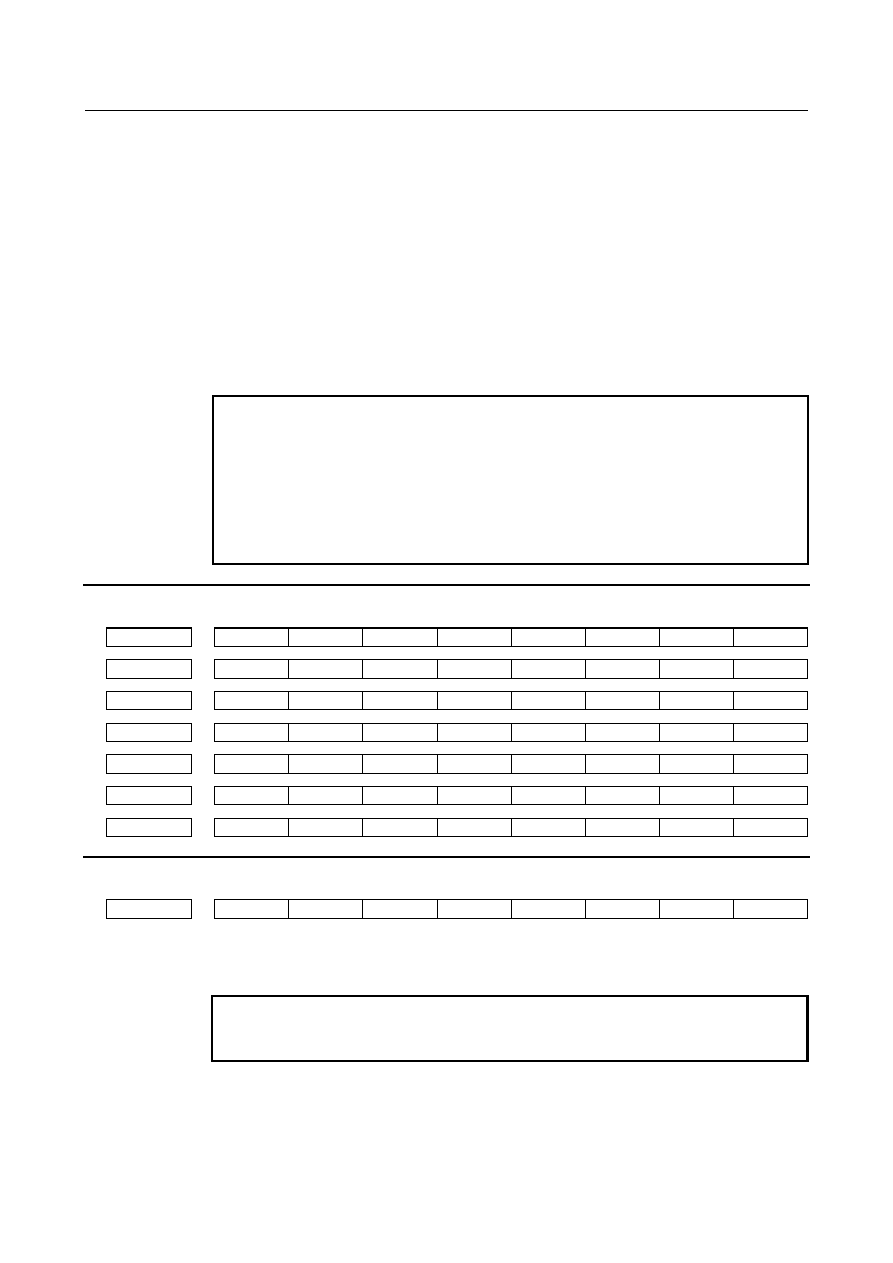
Signal address 


#7 

#6 

#5 

#4 

#3 

#2 

#1 

#0 

Gn031 


PKESS2 

PKESS1 


Gn064 


ESRSYC 


Gn122 


PKESS2 

PKESS1 


Gn264 


ESSYC4 

ESSYC3 

ESSYC2 

ESSYC1 


Gn265 


PKESE4 

PKESE3 

PKESE2 

PKESE1 


Fn043 


SYCAL4 

SYCAL3 

SYCAL2 

SYCAL1 


Fn044 


SYCAL 


Parameter 


#7 

#6 

#5 

#4 

#3 

#2 

#1 

#0 

3704 


SSY 


[Input type]  Parameter input 


[Data type]  Bit path 


NOTE 


When this parameter is set, the power must be turned off before 
operation is continued. 


#5  SSY

  Simple synchronous spindle control by each spindle is: 

0: 

Not performed. 

1: 

Performed. 

The master axis and slave axis of simple synchronous spindle control  can be selected 
from the arbitrary spindles. 

B-64693EN-1/01


10. SPINDLE SPEED FUNCTION


- 1763 - 

The target spindle of simple synchronous spindle control is set in parameter No. 4821. 
In addition, the following signals affect the control. 


Signals of simple synchronous control of each spindle ESSYCs 


Parking signals of simple synchronous control of each spindle PKESEs 


#7 

#6 

#5 

#4 

#3 

#2 

#1 

#0 

4800 


SPK 

EPZ 


[Input type]  Parameter input 


[Data type]  Bit 


NOTE 


When at least one of these parameters is set, the power must be 
turned off before operation is continued. 


#6  EPZ

  When the parking signal is switched in the reference position established state during Cs 

contour control exercised using spindle command synchronous control: 
0: 

Reference position established state is continued. 

1: 

Reference position established state is canceled. 

If this parameter is set, the same reference position return operation as manual reference 
position return is performed with the G28 command immediately after the parking signal 
is switched.   
The G00 command performs a positioning operation including reference position return 
(when bit 1 (NRF) of parameter No.3700 is set to 0). 


#7  SPK

  As the parking signals for spindle command synchronous control: 

0: 

PKESS1<Gn122.6> (first spindle) and PKESS2<Gn122.7> (second spindle) are 
used. 

1: 

PKESS1<Gn031.6> (first spindle) and PKESS2<Gn031.7> (second spindle) are 
used. 


NOTE 

1  This parameter is valid only when bit 5 (SSY) of parameter No. 

3704 is set to 0. 

2  If the parking signals PK7 and PK8 for synchronization control are 

used when spindle command synchronous control and 
synchronization control are used at the same time, set bit 7 (SPK) 
of parameter No.4800 to 1 to use the parking signals PKESS1 and 
PKESS2 for spindle command synchronous control as 
<Gn031.6,Gn031.7>. 


#7 

#6 

#5 

#4 

#3 

#2 

#1 

#0 

3716 


A/Ss 


[Input type]  Parameter input 


[Data type]  Bit spindle 


NOTE 


When this parameter is set, the power must be turned off before 
operation is continued. 


#0  A/Ss

  Spindle motor type is : 

0: 

Analog spindle. 

10. SPINDLE SPEED FUNCTION


B-64693EN-1/01


- 1764 - 

1: 

Serial spindle. 


3717 


Spindle amplifier number to each spindle 


NOTE 


When this parameter is set, the power must be turned off before 
operation is continued. 


[Input type]  Parameter input 


[Data type]  Byte spindle 

[Valid data range]  0 to Maximum number of controlled axes 

Set a spindle amplifier number to be assigned to each spindle. 
0: 

No spindle amplifier is connected. 

1: 

Spindle motor connected to amplifier number 1 is used. 

2: 

Spindle motor connected to amplifier number 2 is used. 

to 
n: 

Spindle motor connected to amplifier number n is used. 


4821 


Master axis of each slave spindle under simple synchronous spindle control 


NOTE 


When this parameter is set, the power must be turned off before 
operation is continued. 


[Input type]  Parameter input 


[Data type]  Byte spindle 

[Valid data range]  0 to Maximum number of controlled spindle axes (within a path) 

When a spindle is set as a slave spindle in spindle command synchronous control on each 
spindle, set which spindle (master spindle) the slave spindle is to be synchronized with. 
 
[Examples of parameter setting] 

When spindle command synchronous control is exercised with the first spindle 
selected as a master spindle and the second spindle selected as a slave spindle: 


No.4821(1)=0 


No.4821(2)=1 


No.4821(3)=0 


No.4821(4)=0 


When spindle command synchronous control is exercised with four spindles under 
the following combinations: 


(Two combinations, namely, first spindle (master spindle)/ second spindle (slave 
spindle), and third spindle (master spindle)/fourth spindle (slave spindle)) 


No.4821(1)=0 


No.4821(2)=1 


No.4821(3)=0 


No.4821(4)=3 


B-64693EN-1/01


10. SPINDLE SPEED FUNCTION


- 1765 - 

NOTE 

1  This parameter is valid if bit 5 (SSY) of parameter No.3704 is set to 

1. 

2  The setting of a slave spindle as a master spindle is invalid. Be 

sure to set 0 for a spindle that is to function as a master spindle. 

3  In this parameter, set a spindle number within the same path. 


4826 


Allowable error count for the error pulses between two spindles in the simple synchronization spindle 

control mode 


[Input type]  Parameter input 


[Data type]  Word spindle 


[Unit of data]  Detection unit 

[Valid data range]  0 to 32767 

Set the allowable error count for the error pulses between two spindles in the simple 
synchronization spindle control mode. 
This parameter is used to check a spindle synchronization error phase difference. 
When a spindle synchronization error equal to or greater than the value set in this 
parameter is detected, the spindle phase error monitor signals SYCAL<Fn044.4> and 
SYCALs are set to “1”. 
 

NOTE 

1  The detection unit per pulse depends on the spindle control mode 

(Cs contour control, rigid tapping, or spindle positioning). 

2  Set this parameter for a spindle that is to function as a slave 

spindle. Set 0 for the master spindle. 

3  In the spindle rotation control mode, synchronization error detection 

is not performed. 


Alarm and message 

Number 

Message 

Description 

PS0194 

SPINDLE COMMAND IN 
SYNCHRO-MODE 

A Cs contour control mode, spindle positioning command, or 
rigid tapping mode was specified during the spindle 
synchronous control mode or spindle command synchronous 
control mode.   


Caution 

  CAUTION 

1  As an output signal for monitoring a phase error during spindle command 

synchronous control, the phase error monitor signal SYCAL is available. The 
action to be taken when a phase error is detected depends on the specifications 
of the machine tool builder. 

2  In multi-path control, spindle command synchronous control cannot be exercised 

on spindles each belonging to a different path. 


Reference item 

For details of the parameters Nos.4000 to 4539, signals, and alarms for the serial spindle control unit, 
refer to the manuals related to serial spindles listed below. 
FANUC AC SPINDLE MOTOR 

α

i

 series PARAMETER MANUAL (B-65280EN) 


10. SPINDLE SPEED FUNCTION


B-64693EN-1/01


- 1766 - 

10.18 

SPINDLE COMMAND SYNCHRONOUS CONTROL 
INDEPENDENT PITCH ERROR COMPENSATION 
FUNCTION 

Overview 

When Cs contouring control axes are placed under spindle command synchronous control, pitch error 
compensation can be exercised on the master spindle and slave spindle independently of each other. 
 
With the bi-directional pitch error compensation option, bi-directional pitch error compensation can also 
be enabled. 
 

Explanation 

When the master spindle is exercising Cs contouring control in spindle command synchronous control, 
the slave spindle is also placed in the Cs contouring control mode. 
An address and position related to a move command are displayed only for the master spindle, and the 
slave spindle performs the same operation as specified by the move command for the master spindle. The 
same pitch error compensation as applied to the master spindle is applied to the slave spindle. 
The same timing and compensation amount of pitch error compensation are used for the master spindle 
and slave spindle. 
 
A pitch error compensation amount different from that for the master spindle can be applied to the slave 
spindle by setting bit 1 (EPC) of parameter No.3601 to 1 and setting the parameters for the slave spindle 
(pitch error compensation reference position compensation number, minus side compensation point 
number, and plus side compensation point number) and pitch error compensation data for the slave 
spindle. 
The same timing of pitch error compensation application is applied to the master spindle and slave 
spindle. 
The parameter settings of a pitch error compensation interval and compensation magnification for the 
master spindle are valid. 
Pitch error compensation point numbers specific to the slave spindle are required in addition to those used 
for the master spindle. 
 
When bi-directional pitch error compensation is used, a different type of pitch error compensation can be 
applied to a movement in each of the positive and negative directions. 
 

Example of setting spindle command synchronous control independent pitch error compensation) 


Parameter setting 

Parameter number 

Description 

Setting value 

3601#1 

Enable independent pitch error compensation for Cs contouring 
control axes 

3620 

Reference position compensation number (master spindle) 

60 

3621 

Minus side compensation point number (master spindle) 

61 

3622 

Plus side compensation point number (master spindle) 

68 

3623 

Compensation magnification (common) 

3624 

Compensation point interval (common) 

45000 

3661 (slave spindle number) 

Reference position compensation number (slave spindle) 

69 

3666 (slave spindle number) 

Minus side compensation point number (slave spindle) 

70 

3671 (slave spindle number) 

Plus side compensation point number (slave spindle) 

77 


B-64693EN-1/01


10. SPINDLE SPEED FUNCTION


- 1767 - 

Pitch error compensation data (master spindle side) 

Compensation number 

60 

61 

62 

63 

64 

65 

66 

67 

68 

Setting value 

+1 

-2 

+1 

+3 

-1 

-1 

-3 

+2 

+1 

Compensation value 

+2 

-4 

+2 

+6 

-2 

-2 

-6 

+4 

+2 


Pitch error compensation data (slave spindle side) 

Compensation number 

69 

70 

71 

72 

73 

74 

75 

76 

77 

Setting value 

+3 

+2 

+4 

-3 

-4 

-6 

+4 

+3 

Compensation value 

+6 

+4 

+8 

-6 

-8 

-12 

+8 

+6 

 
Suppose that the settings above are made. When the master spindle under spindle command synchronous 
control outputs the compensation pulses (+2) of compensation number 60, for example, the compensation 
pulses (+6) of compensation number 69 are output to the slave spindle. 
 

Parameter 


#7 

#6 

#5 

#4 

#3 

#2 

#1 

#0 

3601 


EPC 


[Input type]  Parameter input 


[Data type]  Bit path 


NOTE 


When this parameter is set, the power must be turned off before 
operation is continued. 


#1  EPC

  The pitch error compensation on an axis of Cs contour control on the slave spindle side 

during simple synchronous spindle control is: 
0: 

The same as that on the master spindle. 

1: 

Just for the slave spindle. 


3661 


Number of a pitch error compensation position for the reference position for each slave axis when 
independent pitch error compensation is performed under spindle command synchronous control 


NOTE 


When this parameter is set, the power must be turned off before 
operation is continued. 


[Input type]  Parameter input 


[Data type]  Word spindle 

[Valid data range]  0 to 1535 

Set the number of a pitch error compensation position for the reference position. 
 

NOTE 

1  This parameter is valid if pitch error compensation on an axis of Cs 

contour control on the salve side during simple synchronous 
spindle control is carried out just for the slave axis (bit 1 (EPC) of 
parameter No.3601 is set to 1). 

2  The usable number of pitch error compensation positions and their 

range depend on the option configuration. 


10. SPINDLE SPEED FUNCTION


B-64693EN-1/01


- 1768 - 

3666 


Number of the pitch error compensation position at extremely negative position for each slave axis 

when independent pitch error compensation is performed under spindle command synchronous 

control 


NOTE 


When this parameter is set, the power must be turned off before 
operation is continued. 


[Input type]  Parameter input 


[Data type]  Word spindle 

[Valid data range]  0 to 1535 

Set the compensation position number at the farthest end in the negative direction. 
 

NOTE 

1  This parameter is valid if pitch error compensation on an axis of Cs 

contour control on the salve side during simple synchronous 
spindle control is carried out just for the slave axis (bit 1 (EPC) of 
parameter No.3601 is set to 1). 

2  When using the both-direction pitch error compensation function, 

set a compensation position number for a movement in the positive 
direction. 

3  The usable number of pitch error compensation positions and their 

range depend on the option configuration. 


3671 


Number of the pitch error compensation position at extremely positive position for each slave axis 

when independent pitch error compensation is performed under spindle command synchronous 

control 


NOTE 


When this parameter is set, the power must be turned off before 
operation is continued. 


[Input type]  Parameter input 


[Data type]  Word spindle 

[Valid data range]  0 to 1535 

Set the compensation position number at the farthest end in the positive direction. 
 

NOTE 

1  This parameter is valid if pitch error compensation on an axis of Cs 

contour control on the salve side during simple synchronous 
spindle control is carried out just for the slave axis (bit 1 (EPC) of 
parameter No.3601 is set to 1). 

2  When using the both-direction pitch error compensation function, 

set a compensation position number for a movement in the positive 
direction. 

3  The usable number of pitch error compensation positions and their 

range depend on the option configuration. 


B-64693EN-1/01


10. SPINDLE SPEED FUNCTION


- 1769 - 

3676 


Number of the pitch error compensation position at extremely negative position for each slave axis 

when independent both-direction pitch error compensation is performed under spindle command 

synchronous control 


NOTE 


When this parameter is set, the power must be turned off before 
operation is continued. 


[Input type]  Parameter input 


[Data type]  Word spindle 

[Valid data range]  0 to 1535 

When using both-direction pitch error compensation,  set the  compensation position 
number at the farthest end in the negative  direction for a movement in the negative 
direction. 
 

NOTE 

1  This parameter is valid if pitch error compensation on an axis of Cs 

contour control on the salve side during simple synchronous 
spindle control is carried out just for the slave axis (bit 1 (EPC) of 
parameter No.3601 is set to 1). 

2  The usable number of pitch error compensation positions and their 

range depend on the option configuration. 


3681 


Pitch error compensation value at the reference position when a movement is made to the reference 

position in the direction opposite to the reference position return direction for each slave axis in the 

case where independent both-direction pitch error compensation is performed under spindle command 

synchronous control 


NOTE 


When this parameter is set, the power must be turned off before 
operation is continued. 


[Input type]  Parameter input 


[Data type]  Word spindle 

[Valid data range]  -32767 to 32767 

By using an absolute value, set a pitch error compensation value at the reference position 
when a movement is made in the negative direction  if the reference position return 
direction (bit 5 (ZMI) of parameter No.1006) is positive or when a movement is made in 
the positive direction if the reference position return direction (bit 5 (ZMI) of parameter 
No.1006) is negative. 
 

NOTE 


This parameter is valid if pitch error compensation on an axis of Cs 
contour control on the salve side during simple synchronous 
spindle control is carried out just for the slave axis (bit 1 (EPC) of 
parameter No.3601 is set to 1). 


Caution 

Usable numbers and ranges of pitch error compensation points 

Option configuration 

Number of pitch error 

compensation points 

Pitch error 

compensation range 

Stored type pitch error compensation only 

1536 

    0 to 1535 


Content      ..     224      225      226      227     ..