FANUC Series 0i-MODEL F Plus. CONNECTION MANUAL (FUNCTION) - page 224
 

  Index      Manuals     FANUC Series 0i-MODEL F Plus. CONNECTION MANUAL (FUNCTION) B-64693EN-1/01


Search            copyright infringement  


Content      ..     222      223      224      225     ..


FANUC Series 0i-MODEL F Plus. CONNECTION MANUAL (FUNCTION) - page 224


10. SPINDLE SPEED FUNCTION


B-64693EN-1/01


- 1746 - 


By externally setting the 12-bit orientation external stop position command signal and inputting the 
spindle orientation command signal, the spindle can always be stopped at an arbitrary orientation 
position within one spindle rotation. 


Least input increment 

Least input increment of the stop position for spindle orientation can be changed by bit 0 (ORPUNT) of 
parameter No.4542. 
Moreover, data range are changed at the stop position (parameters Nos.4031 and 4204), stop position shift 
amount (parameters Nos.4077 and 4228), in-position width (parameters Nos.4075 and 4226) and spindle 
orientation signals with the stop position externally set . Detail is shown in Table 10.15 (a) below. 
 

Table 10.15 (a) 


Bit 0 (ORPUNT) of No.4542 

Least input increment [deg] 

360/4096=0.08789 

360/32768=0.01098 

Stop position for orientation 

Data range of parameters Nos.4031,4204 

0 to 4095 

0 to 32767 

Stop position shift amount for orientation 

Data range of parameters Nos.4077,4228 

-4095 to 4095 

-32767 to 32767 

Detection level for the spindle orientation   

completion signal 

Data range of parameters Nos.4075,4226 

0 to 100 

0 to 1000 

Spindle orientation signals   

with the stop position externally set 

Data range of signals below 

SH00A to SH14A<Gn078,Gn079>, 
SH00B to SH14B<Gn080,Gn081>, 

SH00C to SH14C<Gn208,Gn209>, 

SH00D to SH14D<Gn270,Gn271> 

0 to 4095 

0 to 32767 


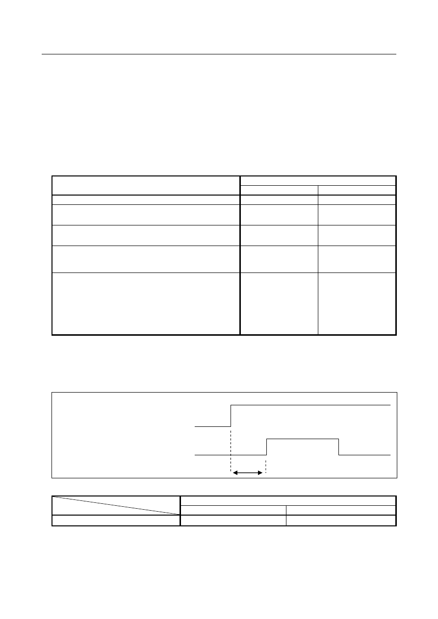
Wait time after changing signals with stop position externally set 

When bit 0 (ORPUNT) of parameter No.4542 is set to 1, the wait time from the spindle orientation 
signals with the stop position externally set change to the commanded orientation command signal is 
reduced. Table 10.15 (b) is shown the wait time. 


Table 10.15 (b) 


Bit 0 (ORPUNT) of No.4542 

Wait time  T[msec] 

50 


For the function  of spindle orientation by a position coder, refer to "FANUC SPINDLE MOTOR 

α

series PARAMETER MANUAL (B-65280EN)", too.


Spindle orientation signals with the stop 

position externally set 

SH00A to SH14A 

Spindle orientation command signals 

ORCMA 

B-64693EN-1/01


10. SPINDLE SPEED FUNCTION


- 1747 - 

Signal 

Spindle orientation signal SOR<Gn029.5> 

  [Classification]  Input signal 
 

[Function]  The spindle or the spindle motor is rotated at a constant 


[Operation]  When the spindle orientation signal turns to “1” and the spindle stop signal *SSTP turns 

to “0”, a spindle speed command which lets the spindle rotate at the constant speed set by 
parameter No. 3732 is output. The enable signal ENB also turns to “1”. This signal is 
disabled when the spindle stop signal is “1”.   
In the machining center system, when the spindle speed for orientation is set by bit 1 
(GST) of parameter No. 3705 and the SOR signal is input, the CNC outputs the spindle 
speed command corresponding to the speed set to parameter 3732 with an output polarity 
set by bit 5 (ORM) of parameter No. 3706, but the gear select signal does not change.   
For example, if the SOR signal is turned to 1 with high gear selected, and the speed set to 
parameter No. 3732 is in the low gear range, the gear select signal does not change and 
the command output is calculated and output to obtain the set speed at high gear. 
When the spindle motor speed is set by bit 1 (GST) of parameter No. 3705=1, the 
command output is output regardless of gear select signal. When the spindle motor speed 
is set, it is used for gear shift. 
Example of usage is shown below: 


10. SPINDLE SPEED FUNCTION


B-64693EN-1/01


- 1748 - 

Spindle orientation command signals 
 

ORCMA<Gn070.6> : For first spindle 


ORCMB<Gn074.6> : For second spindle 


ORCMC<Gn204.6> : For third spindle 


ORCMD<Gn266.6> : For fourth spindle 

  [Classification]  Input signal 
 

[Function]  These signals specify spindle orientation for serial spindle amplifiers. 

For details of the sequence, refer to "FANUC SPINDLE  MOTOR 

a

i

  series 

PARAMETER MANUAL (B-65280EN)". 
 

Spindle orientation signals with the stop position externally set 
 

SH00A to SH14A<Gn078,Gn079> : For first spindle 


SH00B to SH14B<Gn080,Gn081> : For second spindle 


SH00C to SH14C<Gn208,Gn209> : For third spindle 


SH00D to SH14D<Gn270,Gn271> : For fourth spindle 

  [Classification]  Input signal 
 

[Function]  This command is used for specifying a stop position with an absolute position within one 

rotation in the following equation: 

Bit 0(ORPUNT) of parameter No.4542 is set to 0 : 


Effective 12bit (SH00A to SH11A, SH00B to SH11B, SH00C to SH11C, SH00D to 
SH11D) 


Bit 0(ORPUNT) of parameter No.4542 is set to 1 : 


Effective 15bit (SH00A to SH14A, SH00B to SH14B, SH00C to SH14C, SH00D to 
SH14D) 


where Pi = 0 when SHiA = 0, or Pi = 1 when SHiA = 1. 
For details of the sequence, refer to "FANUC SPINDLE  MOTOR 

a

i

  series 

PARAMETER MANUAL (B-65280EN)". 


NOTE 


When bit 0 (ORPUNT) of parameter No.4542 is set to 0, after the spindle 
orientation signals with the stop position externally set is set, change the 
orientation signals ORCM after waiting for 50msec or more.   
When bit 0 (ORPUNT) of parameter No.4542 is set to 1, the wait time is 
unnecessary. 


Signal address 


#7 

#6 

#5 

#4 

#3 

#2 

#1 

#0 

Gn070 


ORCMA 


Gn078 


SH07A 

SH06A 

SH05A 

SH04A 

SH03A 

SH02A 

SH01A 

SH00A 


Gn079 


SH14A 

SH13A 

SH12A 

SH11A 

SH10A 

SH09A 

SH08A 


Gn074 


ORCMB 


Gn080 


SH07B 

SH06B 

SH05B 

SH04B 

SH03B 

SH02B 

SH01B 

SH00B 


Pi)

(2

4096

360

deg

i

11

0

i

×

×

=

=

Σ


position

Stop

Pi)

(2

32768

360

(deg

i

14

0

i

×

×

=

=

Σ


position

Stop

B-64693EN-1/01


10. SPINDLE SPEED FUNCTION


- 1749 - 

Gn081 


SH14B 

SH13B 

SH12B 

SH11B 

SH10B 

SH09B 

SH08B 


Gn204 


ORCMC 


Gn208 


SH07C 

SH06C 

SH05C 

SH04C 

SH03C 

SH02C 

SH01C 

SH00C 


Gn209 


SH14C 

SH13C 

SH12C 

SH11C 

SH10C 

SH09C 

SH08C 


Gn266 


ORCMD 


Gn270 


SH07D 

SH06D 

SH05D 

SH04D 

SH03D 

SH02D 

SH01D 

SH00D 


Gn271 


SH14D 

SH13D 

SH12D 

SH11D 

SH10D 

SH09D 

SH08D 


Parameter 


#7 

#6 

#5 

#4 

#3 

#2 

#1 

#0 

3729 


ORTs 


[Input type]  Parameter input 


[Data type]  Bit spindle 


#0  ORTs

  When a serial spindle is used, the spindle orientation function of stop position external 

setting type based on the position coder is: 
0: 

Not performed. 

1: 

Performed. 


NOTE 


When bit 0 (ORPUNT) of parameter No.4542 is set to 1, if bit 0 
(ORTs) of parameter No.3729 is changed, the power must be 
turned off before operation is continued.   


4031 


Stop position in orientation by a position coder (MAIN spindle) 


4204 


Stop position in orientation by a position coder (SUB spindle) 


[Input type]  Parameter input 


[Data type]  Word spindle 


[Unit of data]  Detection unit 


[Valid data range]  Depend on the bit 0 (ORPUNT) of parameter No.4542 setting (Refer to the table below) 

Bit 0 (ORPUNT) of No.4542 

Least input increment 

Valid data range 

360/4096= 0.08789 

0 to 4095 

360/32768= 0.01098 

0 to 32767 

 
Each of these parameters specifies a stop position in orientation by a position coder. 
These parameters are valid when bit 0 (ORT) of parameter No.3729 is set to 0. 
 

4075 


Orientation completion signal detection level (limits of in-position)

MAIN spindle


4226 


Orientation completion signal detection level (limits of in-position)

SUB spindle


[Input type]  Parameter input 


[Data type]  Word spindle 


[Unit of data]  Detection unit 


[Valid data range]  Depend on the bit 0 (ORPUNT) of parameter No.4542 setting (Refer to the table below) 

10. SPINDLE SPEED FUNCTION


B-64693EN-1/01


- 1750 - 

Bit 0 (ORPUNT) of No.4542 

Valid data range 

0 to 100 

0 to 1000 

 
This data is used to set the detecting level of orientation completion signal (ORARA). 
ORARA is assumed to be 1 if the position error is within the setting. 
 

4077 


Stop position shift amount in orientation by a position coder(MAIN spindle) 


4228 


Stop position shift amount in orientation by a position coder(SUB spindle) 


[Input type]  Parameter input 


[Data type]  Word spindle 


[Unit of data]  Detection unit 


[Valid data range]  Depend on the bit 0 (ORPUNT) of parameter No.4542 setting (Refer to the table below) 

Bit 0 (ORPUNT) of No.4542 

Least input increment 

Valid data range 

360/4096= 0.08789 

-4095 to 4095 

360/32768= 0.01098 

-32767 to 32767 

 
Each of these parameters specifies a stop position shift amount in orientation by a 
position coder. 
This parameter is valid no matter what the setting of bit 0 (ORT) of parameter No.3729 
is. 


#7 

#6 

#5 

#4 

#3 

#2 

#1 

#0 

4542 


ORPUNT 


[Input type]  Parameter input 


[Data type]  Bit spindle 


  #0  ORPUNT

  Least input increment for Stop position of spindle orientation, Stop position shift amount, 

In-position width 
0: 

360/4096 = 0.08789 [deg] 

1: 

360/32768 = 0.01098 [deg] 


  CAUTION 


In the 

α

i

 position coder, the effect is not achieved by the fine 

resolution application of stop position because the sensor 
resolution is 4096p/rev. 


NOTE 


To use this function, the corresponding serial spindle software is 
required. 


Alarm and message 

Number 

Message 

Description 

SP1258 

ILLEGAL SPINDLE PARAMETER 
SETTING (SOFT) 

The parameter is an illegal setting. Check as follows. 
 
- Bit 0 (ORPUNT) of parameter No.4542 is set to 1 the 
spindle control software that does not support this function. 
Set 0 to the bit 0 (ORPUNT) of parameter No.4542. 


B-64693EN-1/01


10. SPINDLE SPEED FUNCTION


- 1751 - 

Diagnosis data 

445 


Position data of position coder (pulse


[Data type]  2-word spindle 


[Unit of data]  Pulse   


[Valid data range]  Depend on the bit 0 (ORPUNT) of parameter No.4542 setting (Refer to the table below) 

Bit 0 (ORPUNT) of No.4542 

Valid data range 

0 to 4095 

0 to 32767 


  In serial spindle, position coder signal pulse data from one-rotation signal is displayed as 

the spindle position data. It’s effective when bit 1 (SPP) of parameter No.3117 is set to 1. 


  For displaying spindle position data, spindle orientation must be executed once. 


449 


Position data of position coder (angle) 


[Data type]  Real spindle 


[Unit of data]  Refer to the table below 


[Valid data range]  0 to 359.999[deg] 

 
Diagnosis data No.449 indicates spindle angle from the one-rotation signal when  bit 1 
(SPP) of parameter No.3117 is set to 1. Spindle angle displays to three decimal places. It 
is available for serial spindle. To display spindle angle, spindle orientation must be 
performed once. Unit of spindle angle data is as follows. 
 

Bit 0 (ORPUNT) of No.4542 

Unit of data [deg] 

0.088 

0.011 


NOTE 


Once spindle orientation is performed after power-on, position data 
can be read. To read position data, set bit 1(SPP) of parameter No. 
3117 to 1. 


(Except when maintenance is performed, bit 1(SPP) of parameter 
No. 3117 must be set to 0.) 


Caution 

  CAUTION 

1  To perform spindle orientation by using the spindle control unit, the signals of the 

spindle control unit must be used. 


To perform serial spindle orientation by using a position coder (to perform serial 
spindle orientation with the stop position set externally), the serial spindle control 
unit signals must be used. 

2  When the function of spindle orientation with the stop position set externally is 

used, the parameters for stop positions in orientation by a position coder 
(parameters Nos.4031 and 4204) are invalid. 

3  In the 

a

i

 position coder, the effect is not achieved by the fine resolution 

application of stop position because the sensor resolution is 4096p/rev. 

4  The precision for stop position is depended by the specification of sensor. 


10. SPINDLE SPEED FUNCTION


B-64693EN-1/01


- 1752 - 

Note 

NOTE 

1  Stop position external setting type orientation cannot be used in Magnetic sensor 

method spindle orientation. 

2  Spindle orientation with the spindle positioning function differs from that 

described in this section. For details, see "Spindle Positioning." 


Reference item 

Manual name 

Item name 

FANUC AC SPINDLE MOTOR 

a

i

 series PARAMETER MANUAL 

(B-65280EN) 

Position coder method spindle orientation 


10.16 

SPINDLE OUTPUT SWITCHING 

Overview 

Spindle output switching switches between the two motor windings, one for low speed and the other for 
high speed, incorporated into the special spindle motors. This ensures that the spindle motor demonstrates 
stable output characteristics over a wide range. 
Since spindle output switching is a function of the spindle control unit, also refer to the manual for the 
spindle control unit being used. 
This section describes the relationship between spindle output switching and the spindle control function 
in the CNC. 
 

NOTE 


Ladder sequence of the spindle output switching can be easily incorporated by 
using PMC function. The FANUC LADDER-III CD, function block that can be 
incorporated easily spindle output switching is stored in the form of a library. 


For details on library of function block, refer to the documents in the FANUC 
LADDER-III CD. For details on function block, refer to the PMC 
PROGRAMMING MANUAL (B-64513EN). 


Explanation 

  - 

Operation of spindle output-switchable spindle motor 

To switch the spindle output characteristics, the windings are usually switched using a relay. Prior to the 
completion of winding switching, the spindle rotates free from drive power. 
Output switching changes the relationship between a speed command, issued from the CNC to the spindle, 
and the output characteristics of the spindle motor. However, the relationship between the speed 
command and spindle motor speed is not changed. 
 

  - 

Spindle output switching timing 

During actual machining, the spindle is usually controlled in the following way. 
(1)  Constant spindle speed during cutting, such as milling 
(2)  Continuously changing spindle speed during cutting, such as in constant surface speed control 
(3)  Controlling the position loop including the spindle motor during rigid tapping, spindle positioning, 

Cs contour control, etc. 

For applications such as those in (1), we recommend switching the output characteristics for low speed 
and high speed by using the spindle motor speed detection signal of the spindle control unit. 
For applications such as those described in (2) and (3), the spindle must not rotate with no drive power 
applied during cutting or positioning. It is necessary for the output characteristics to be  switched 
appropriately before machining or for output switching to be masked by using a PMC ladder sequence. 
 

B-64693EN-1/01


10. SPINDLE SPEED FUNCTION


- 1753 - 

  - 

Output switching and gear switching 

Spindle output switching ensures that the spindle motor demonstrates stable characteristics over a wide 
range, and eliminates the requirement of a mechanical spindle gear switching mechanism. 
In creating a PMC ladder sequence for output switching, however, using the gear switching of the CNC’s 
spindle control function may facilitate programming. 
Note the following points when using gear switching for CNC spindle control for output switching with a 
machine tool having no mechanical gear switching mechanism. 


When gear selection output signals, GR1O and GR2O <Fn034.0, 1>, are used (for machining centers 
in which constant surface speed control is not provided and GTT, bit 4 of parameter No. 3706, is set 
to 0) 
Set two gears, which are almost the same. 
(Example: Value of parameter No.3741 = value of parameter No.3742 -  1, value of No.3742 = 
Maximum spindle speed) 
When parameter No.3741 is equal to parameter No.3742, the CNC judges that one gear is used, and 
does not output the GR2O signal. 


The parameters related to gear switching points, SGT, bit 3 of parameter No.3705, and SGB, bit 2 of 
parameter No.3705, parameters Nos.3761 and 3751 can be used. 


In usual spindle control, depending on the speed at switching points, the speed specified by the 
spindle speed command may differ slightly from the actual speed in the area where the maximum 
spindle speed is set to the maximum speed - 1. (This is because the spindle motor speed, specified by 
the speed command, is calculated based on the settings of parameters Nos.3741 to 3744.) 


This does not apply to rigid tapping. (Because the machine tool is controlled using the feedback 
signal from the detector in the position loop.) 


When gear selection input signals, GR1 and GR2 <Gn028.1, 2>, are used (for lathes or machining 
centers in which constant surface speed control is provided or GTT, bit 4 of parameter No.3706, is 
set to 1) 


Parameter settings are read according to the input signal information. Unlike the GR2O and GR1O 
signals, these signals do not require special parameter settings. 
Example) 
 

When parameters Nos.3741 and 3742 are set to the maximum spindle speed. 


Create a PMC sequence that specifies the following.   


For gear 1, set GR1 and GR2 <Gn028.1, 2> to “0”. 


For gear 2, set GR2 <Gn028.2> to “0” and set GR1 <Gn028.1> to “1”. 


The PMC must determine the switching timing on the basis of some information. 


Reference item 

Manual name 

Item name 

CONNECTION MANUAL (FUNCTION) (This manual) 

Spindle speed control 
Rigid tapping 

FANUC AC SPINDLE MOTOR 

a

i

 series PARAMETER MANUAL 

(B-65280EN) 

Spindle switching control


Content      ..     222      223      224      225     ..