FANUC Series 0i-MODEL F Plus. CONNECTION MANUAL (FUNCTION) - page 205
 

  Index      Manuals     FANUC Series 0i-MODEL F Plus. CONNECTION MANUAL (FUNCTION) B-64693EN-1/01


Search            copyright infringement  


Content      ..     203      204      205      206     ..


FANUC Series 0i-MODEL F Plus. CONNECTION MANUAL (FUNCTION) - page 205


10. SPINDLE SPEED FUNCTION


B-64693EN-1/01


- 1594 - 

Cs axis origin established state signals 

First spindle: CSPENA<Fn048.4>, Second spindle: CSPENB<Fn052.4>,   
Third spindle: CSPENC<Fn171.4>, Fourth spindle: CSPEND<Fn269.4> 


[Classification]


Output signal 


[Function]  These signals indicate that Cs coordinate establishment processing is available. 


[Output cond.]


These signal is 1 in the following case : 

A reference position return is completed normally in the Cs contour control mode. 

These signal is 0 in the following case : 

A spindle alarm is detected or the spindle motor rotation speed exceeds the 
maximum allowable rotation speed (specified in parameter No. 4020). 


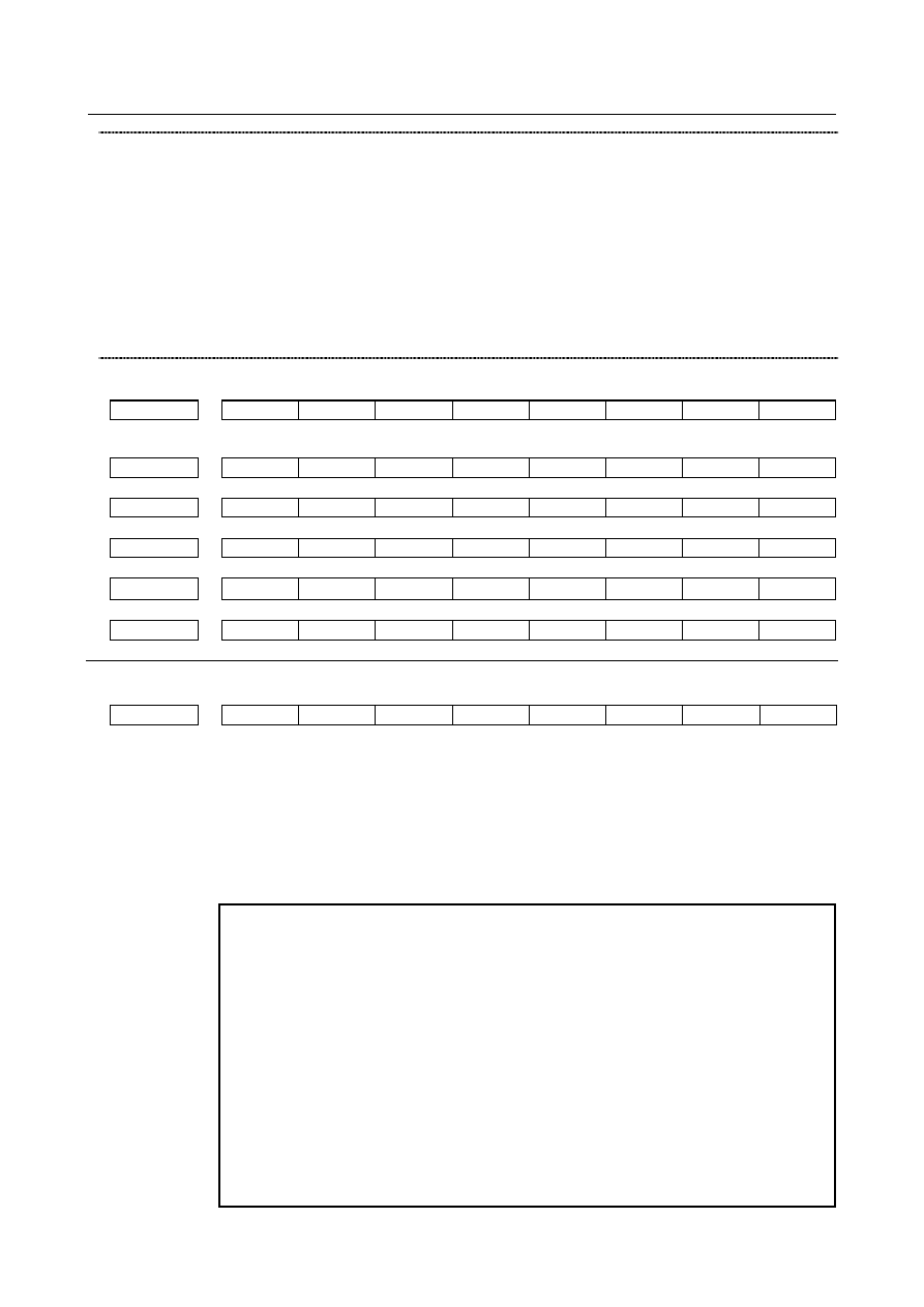
Signal address 


#7 

#6 

#5 

#4 

#3 

#2 

#1 

#0 

Gn274 


CSFI4 

CSFI3 

CSFI2 

CSFI1 


#7 

#6 

#5 

#4 

#3 

#2 

#1 

#0 

Fn048 


CSPENA 


Fn052 


CSPENB 


Fn171 


CSPENC 


Fn269 


CSPEND 


Fn274 


CSFO4 

CSFO3 

CSFO2 

CSFO1 


Parameter 


#7 

#6 

#5 

#4 

#3 

#2 

#1 

#0 

1005 


ZRNx 


[Input type]  Parameter input 


[Data type]  Bit axis 


#0  ZRNx

  If a move command other than G28 is specified by automatic operation when no 

reference position return is performed yet after the power is turned on:   
0: 

The alarm PS0224, "ZERO RETURN NOT FINISHED." is issued. 

1: 

Operation is performed without issuing an alarm. 


NOTE 

1  The state in which a reference position has not been established 

refers to the following state: 

-  When an absolute position detector is not used and reference 

position return has not been performed even once after power-up 

-  When an absolute position detector is used and the association of 

the machine position with the position detected with the absolute 
position detector has not been completed (See the description of 
bit 4 (APZx) of parameter No. 1815.) 

2  When the Cs axis coordinates are to be set up, set this parameter 

to 0. 

3  To use a function that establishes the reference point and makes a 

movement with a command other than G28, such as an axis of Cs 
contour control, set this parameter to 1. 

B-64693EN-1/01


10. SPINDLE SPEED FUNCTION


- 1595 - 


#7 

#6 

#5 

#4 

#3 

#2 

#1 

#0 

3712 


CSF 


[Input type]  Parameter input 


[Data type]  Bit 


#2  CSF

  In the Cs contour control mode, the function for setting machine coordinates and absolute 

coordinates based on the machine position of the spindle if the origin is already set up is: 
0: 

Disabled. 

1: 

Enabled. 


#7 

#6 

#5 

#4 

#3 

#2 

#1 

#0 

4353 


CSPTRE 


[Input type]  Parameter input 


[Data type]  Bit spindle 


#5  CSPTRE

  Specifies whether to enable Cs axis positional data transfer, as follows: 

0: Disable. 
1: Enable. 
 
To use this function, reset bit 7 (RFCHK3) of parameter No. 4016 to 0. 


Alarm and message 

Number 

Message 

Description 

PS5346 

REFERENCE POSITION RETURN 
IS NOT PERFORMED 

The coordinate establishment of the Cs contour control axis is 
not made. Perform a manual reference position return. 
1.  When Cs coordinate establishment is made for the Cs-axis 

for which the Cs-axis reference position status signal 
CSPENx is 0 

2.  When positional information is not sent from the spindle 

amplifier 

3.  When the servo off state is entered during the start of 

Cs-axis coordinate establishment 

4.  When the Cs-axis is subjected to synchronous control or 

superposition control 

5.  When the emergency stop state is entered during 

coordinate establishment 

6.  When an attempt is made to release composite control for 

the Cs axis being subjected to coordinate establishment 

7.  When an attempt is made to start synchronous, composite, 

or superposition control for the Cs axis being subjected to 
coordinate establishment. 


Reference item 

Manual name 

Item name 

CONNECTION MANUAL (FUNCTION) 
(This manual) 

Cs contour control 


10. SPINDLE SPEED FUNCTION


B-64693EN-1/01


- 1596 - 

10.11.5 

Cs Contour Control Manual High-Speed Reference Position 
Return 

Overview 

This function makes it possible to perform high-speed type reference position return as manual reference 
position return after the reference position for the Cs contour control axis is established (ZRF <Fn120> = 
1). 
 

Explanation 

As manual reference position return after the reference position for the Cs contour control axis is 
established, 

When the bit 6 (CHM) of parameter No. 3729 is set to 0: 


Spindle orientation is performed. 

When the bit 6 (CHM) of parameter No. 3729 is set to 1: 


High-speed type reference position return is performed. 


Parameter 


#7 

#6 

#5 

#4 

#3 

#2 

#1 

#0 

3729 


CHMs 


[Input type]  Parameter input 


[Data type]  Bit spindle 


#6  CHMs

  Manual reference position return after the reference position for the Cs contour control 

axis is established is performed as: 
0: 

Spindle orientation operation. 

1: 

High-speed type of reference position return operation. 


Limitation 

  - 

Manual reference position return before the reference position is established 

If manual reference position return is performed on the Cs contour control axis before the reference 
position is established, the return is performed as spindle orientation even if bit 6 (CHM) of parameter No. 
3729 is set to 1. 
 

10.12 

MULTI-SPINDLE CONTROL 

Overview 

In addition to the first spindle, the second to fourth spindles can be controlled using an S command from 
the CNC. 
Spindle commands are specified using a single S command as conventionally done. A spindle is selected 
depending on the signal from the PMC or the address P command. 
Gear change between two stages can be made for the second, third, and fourth spindles in the same 
manner as for the first spindle. 
A maximum speed can be set for each spindle, and the speed of each spindle can be clamped to the 
corresponding maximum speed (according to the setting in parameter No. 3772). 
The position coder interfaces for the second to fourth spindles can be selected and added. 
The first to fourth position coders are selected by signals from the PMC. 
 

B-64693EN-1/01


10. SPINDLE SPEED FUNCTION


- 1597 - 

NOTE 

Multi-spindle control can be used by setting bit 3(MSP) of parameter No.8133 to 1 
and bit 1(EMS) of parameter No.3702 to 0. 


Explanation 

  - 

Multi-spindle control in machining center 

M


-


Only when the T-type gear change is selected (when the constant surface speed control function is 

enabled(bit 0(SCC) of parameter No.8133 is 1)or when bit 4 (GTT) of parameter No. 3706 is set to 
1), multi-spindle control is enabled. 

-


For information about rigid tapping, see "RIGID TAPPING". 


  - 

Control methods 

There are three types of multi-spindle control methods: a method that can use the SIND (spindle motor 
speed control by the PMC) function only for the first spindle (TYPE-A), a method that can use the SIND 
function for the four spindles independently (TYPE-B), and a method that is equivalent to TYPE-B and 
can use address P to select the spindle to be controlled by the S command. 


  Basic control 1 (Common to TYPE-A and TYPE-B) 

An S command is sent as a speed command to each spindle selected, using a spindle  selection signal 
(SWS1 to SWS4 <Gn027.0-2>, <Gn026.3>). Each spindle rotates at the specified speed. If a spindle is 
not sent a spindle selection signal, it continues to rotate at its previous speed. This allows the spindles to 
rotate at different speeds at the same time. 


Basic control 2 (Common to TYPE-A, TYPE-B, and the method of making 
spindle selection by address P) 

Each spindle also has a spindle stop signal (*SSTP1 to *SSTP4 <Gn027.3-5>, <Gn026.6>) to stop its 
rotation; an unused spindle can still be stopped. 
There is a spindle enable signal to control each spindle; ENB <Fn001.4> controls the first spindle, while 
ENB2 to ENB4 <Fn038.2, 3>, <Fn039.1> control the second and third spindles, respectively. 
The selection of the position coder by the position coder select signals PC2SLC, PC3SLC, and PC4SLC 
<Gn028.7>, <Gn026.0>, <Gn026.1> is used to select between the first to fourth position coders. 
 

  When multi-spindle control is disabled 

When bit 1 (EMS) of parameter No. 3702 is 1, multi-spindle control is disabled. In this case, only the first 
spindle can be controlled using the S command even if more than one spindle is present. 


  Multi-spindle control (TYPE-A) 

When bit 2 (MSI) of parameter No. 3709=0, TYPE-A is used. 
When the first spindle is selected with the SWS1 signal, the SIND signal <Gn033.7> is used to determine 
whether the spindle analog voltage is controlled by the PMC or CNC; then signals R01I to R12I 

10. SPINDLE SPEED FUNCTION


B-64693EN-1/01


- 1598 - 

<Gn032.0  to Gn033.3> are used to set that spindle’s analog voltage. These signals do not affect the 
second to fourth spindles. 
The PMC-based polarity (rotation direction) control signals SGN<Gn033.5> and SSIN <Gn033.6> will 
function for any spindle selected by SWS1 to SWS4. 
The concept of Type A multi-spindle control is outlined below (Fig. 10.12 (a)). 


Fig. 10.12 (a) 


  Multi-spindle control (TYPE-B) 

Select Type B control by setting bit 2 (MSI) of parameter No. 3709 to 1. 
Each spindle has its own SIND, SSIN and SGN signals. 
Each of these signals functions regardless of selection state of the spindle selection signals (SWS1 to 
SWS4). 
When either the spindle selection signals (SWS1 to SWS4) or the SIND signal for the first, second, third, 
or fourth spindle is set to 1, the polarity control signals SSIN, SGN will function. 
The concept of Type B multi-spindle control outlined below (Fig. 10.12 (b)). 


Fig. 10.12 (b) 


  Multi-spindle control:    when a spindle is selected by address P 

If bit 3 (MPP) of parameter No. 3703 is set to 1, a spindle is selected by address P. This control method is 
basically the same as TYPE-B. The first, second, third, and fourth spindles each have their own SIND, 
SSIN, and SGN signals. A spindle is selected by the P command instead of the spindle selection signals 
(SWS1 to SWS4). The relationship between the P code and the selected spindle is set in parameter No. 
3781. 
Polarity (rotation direction) control signals SSIN and SGN for each spindle are valid only for the spindle 
selected by the P command or for the spindle of which SIND signal is 1. 
The concept of multi-spindle control (spindle selection by address P) is outlined below (Fig. 10.12 (c)). 

B-64693EN-1/01


10. SPINDLE SPEED FUNCTION


- 1599 - 


Fig. 10.12 (c) 

 
In case of multi-path control, the P code becomes valid in all paths. For example, suppose that the P code 
to select the first spindle of path 2 is set to 21. When the following is specified in path 1: 
 

S1000 P21; 

Then, 1000 is specified for the first spindle in path 2. Therefore, the same P code cannot be used even in 
different paths. 
 

A spindle is selected by address P 


  Restrictions 

The command for spindle selection by address P and the G code or M code including address P cannot be 
commanded on the same block. If you use the same address,  it may result in the machine behaving 
unexpectedly. Command on separate block. About the function including address P, refer to the appendix 
“LIST OF FUNCTIONS INCLUDE ADDRESS P IN THE PROGRAM COMMAND”. 
 

Extended spindle name 

Usually, S is used as commands for spindles. If the conditions listed below are all satisfied, extended 
spindle names can be used. Extended spindle names can consist of up to three characters beginning with S 
as the first spindle name character, and use of an extended spindle name allows a command to be 
executed for a specific spindle. 
-


The serial (analog) spindle function is enabled. 

-


The multi-spindle control is enabled. 

-


Bit 0 (EEA) of parameter No. 1000 is 1. 

-


Bit 3 (MPP) of parameter No. 3703 is 1. 

-


Bit 1 (ESN) of parameter No. 3798 is 1. 

-


Bit 4 (GTT) of parameter No. 3706 is 1. (for machining center system only) 

 
As the second and third characters of spindle names, any characters from 0 to 9 and from A to Z may be 
set in ASCII code. In spindles, the third spindle name character is not valid unless the second spindle 
name character is set. If a character 0 to 9 is set as the second spindle name character, a character A to Z 
must not be set as the third spindle name character. 
If a spindle name ends with a numeric character, ‘=‘ is required between the spindle name and a specified 
value. 
 

10. SPINDLE SPEED FUNCTION


B-64693EN-1/01


- 1600 - 


Spindle name 

1st character 

(fixed) 

Spindle name 
2nd character 

(No.3738) 

Spindle name 

3rd character 

(No.3739) 

Setting value 

‘S’ 

‘0’ to ‘9’ 

‘0’ to ‘9’ 

‘A’ to ‘Z’ 

‘0’ to ‘9’ 

‘A’ to ‘Z’ 

Correct example <1> 

‘S’ 

Correct example <2> 

Correct example <3> 

Incorrect example 

 
In case of multi-path control, extended spindle names become valid in all paths. For example, suppose 
that the first spindle of path 2 is named SA. When the following is specified in path 1: 
 

SA1000; 

Then, 1000 is specified for the first spindle in path 2. Therefore, the same extended spindle name cannot 
be used even in different paths. 


  Restrictions 

More than one extended spindle name cannot be specified within the same block. Also, ‘S’  and an 
extended spindle name cannot be specified together within the same block. If they are specified together, 
P/S alarm No. 333 is issued. 
When extended spindle names are used, subscripts (MAIN (in parameter No. 3718), SUB (in parameter 
No. 3719) cannot be used. 
When the custom macro function is enabled, the same extended spindle names as reserved words cannot 
be used. They are regarded as reserved words. 
The target spindle for rigid tapping cannot be selected by specifying an extended spindle name. 


  Multi-spindle address P signal 

When extended spindle names are used, the value in parameter  No. 3781 corresponding to the spindle 
number of the spindle name specified last is output to MSP00 to MSP15 <Fn160.0 to Fn161.7>. If a 
command for a spindle has not been specified even once, the value set in parameter No. 3775 is output. 


  Supplement 

When extended spindle names are used, the value of the spindle command specified last is indicated as 
the modal indication of S. 
When the serial (analog) spindle function and multi-spindle control are enabled, the method for selecting 
the target spindle is determined according to the settings of bit 3(MPP) of parameter No. 3703 and bit 1 
(ESN) of parameter No. 3798 as follows: 
 

Bit 3 (MPP) of parameter No. 

3703 

Bit 1 (ESN) of parameter No. 

3798 

Method for selecting target 

Signal selection 

Signal selection 

P command (S_ P_) 

Specification of extended spindle name 

or 

P command (S_ P_) 

 
If MPP and ESN are both set to 1, both the S_P_ command and extended spindle names can be used. 
 

B-64693EN-1/01


10. SPINDLE SPEED FUNCTION


- 1601 - 

NOTE 


Address S indicates a command for all spindles. When multiple spindles are 
used, and bit 3 (MPP) of parameter No. 3703 is 1, a particular spindle must be 
specified by using address P and so on. If spindle name S is set when extended 
spindle names are used, S indicates a particular spindle (except the command 
for clamping at the maximum spindle speed in constant surface control 
(G50(G92)S_)). 


This means that if spindle name S is set when extended spindle names are 
used, a command specifying S only is a command for the spindle named S. 
(Even when P is specified in the same block, it is ignored.) When S is not set in 
a spindle name, a command specifying S only is regarded as a command for the 
spindle for which a command has been issued last. (This is the same as the 
operation of a command specifying only S when multiple spindles are used, 
extended spindle names are not used, and bit 2 (MPA) of parameter No. 3706 is 
set to 1.) 

Example:  When extended spindle names are used, and commands with 

extended spindle names and S_P_ commands are used together 

1. When the first spindle is SA, the second spindle is SB, and 1 is set for the first 

spindle and 2 is set for the second spindle in parameter No. 3781 


If bit 2 (MPA) of parameter No. 3706 is 0 


N10 M03;   


N20 SA100; 


100 is specified for 1st spindle. 


N30 SB200; 


200 is specified for 2nd spindle. 


N40 S200P1; 


200 is specified for 1st spindle. 


N50 S300; 


P/S alarm No. 5305 is issued. 


N60 S200P2;   


N70 S300;   


N80 SA400;   


N90 S500;   


N100 SB400;   


N110 S500;   


If bit 2 (MPA) of parameter No. 3706 is 1 


N10 M03;   


N20 SA100; 


100 is specified for 1st spindle. 


N30 SB200; 


200 is specified for 2nd spindle. 


N40 S200P1; 


200 is specified for 1st spindle. 


N50 S300; 


300 is specified for 1st spindle. 


N60 S200P2; 


200 is specified for 2nd spindle. 


N70 S300; 


300 is specified for 2nd spindle. 


N80 SA400; 


400 is specified for 1st spindle. 


N90 S500; 


500 is specified for 1st spindle. 


N100 SB400; 


400 is specified for 2nd spindle. 


N110 S500; 


500 is specified for 2nd spindle. 


Content      ..     203      204      205      206     ..