FANUC Series 0i-MODEL F Plus. CONNECTION MANUAL (FUNCTION) - page 198
 

  Index      Manuals     FANUC Series 0i-MODEL F Plus. CONNECTION MANUAL (FUNCTION) B-64693EN-1/01


Search            copyright infringement  


Content      ..     196      197      198      199     ..


FANUC Series 0i-MODEL F Plus. CONNECTION MANUAL (FUNCTION) - page 198


10. SPINDLE SPEED FUNCTION


B-64693EN-1/01


- 1538 - 


  Timing chart for switching to spindle positioning mode 


  M code command 


Strobe signal 

   MF 

Spindle stop complete 

signals   SPSTPs 

Spindle position control 


Spindle positioning mode   

signals   MSPOS 

  Spindle enabled 


Spindle unclamp signals 

   SUCLPs 

Spindle unclamp completion   

signals   *SUCPFs 

  Spindle orientation 


Reference position return completion signals 

   ZPx 

Spindle clamp signals 

   SCLPs 

Spindle clamp completion signals 

   *SCPFs 

Auxiliary function completion signal 

   FIN 


  CAUTION 

1  Switching between the spindle rotation mode and spindle positioning mode must 

be performed on the machine side in response to M code commands issued 
from the CNC. 


When the spindle positioning mode is canceled, the spindle becomes ready for 
accepting speed commands such as an S command. Therefore, a PMC ladder 
program must be created so that spindle rotation is not performed when the 
spindle is clamped on the machine side. 
Example:   
 

When the spindle is clamped on the machine side, spindle stop signal *SSTP 
<G029.6> is set to 0. 

B-64693EN-1/01


10. SPINDLE SPEED FUNCTION


- 1539 - 

  CAUTION 

2  When the spindle is clamped on the machine side (by using a device such as a 

clutch or shot pin), the spindle must be disabled. Enabling or disabling the 
spindle means to separately instruct the spindle control unit to enable or disable 
spindle motor operation by the PMC ladder and so on. 


Example: When a serial spindle is enabled, SFRA <G070.5> is set to 1. When 
the serial spindle is disabled, SFRA <G070.5> is set to 0. 


Refer to the manual of the spindle control unit to be connected, and add 
instructions to the ladder program. 


  Spindle positioning 

In the spindle positioning mode, positioning is performed using one of the following two programmed 
commands: 
1) 

Positioning at a semi-fixed angle by specifying an M code 

2) 

Positioning at any angle by specifying an axis address 

The operations performed by using the above two specification methods are the same, except that in 
positioning at any angle, input/output signals related to auxiliary functions are not exchanged. 
The M code used for positioning at a semi-fixed angle is set in parameters Nos. 4962 and 4964 in 
advance. 
 
When positioning at a semi-fixed angle is performed by specifying the M code, specification A or B can 
be selected by setting bit 7 (IMB) of parameter No. 4950. 
 
If specification B is selected, specifying an M code that specifies the spindle positioning angle performs 
operations (1) to (3) below successively. 
(1)  Canceling the spindle rotation mode and switching to the spindle positioning mode 
(2)  Positioning the spindle in the spindle positioning mode 
(3)  Canceling the spindle positioning mode and switching to the spindle rotation mode 
 
If specification A is selected, only the spindle positioning operation is performed in the spindle 
positioning mode. 
 
[Specification A: Bit 7 (IMB) of parameter No. 4950 = 0 ] 
<1>  Suppose that an M code is specified by a program. If an M code is specified in the spindle rotation 

mode, the CNC issues alarm PS0224, "ZERO RETURN NOT FINISHED". 

<2>  Auxiliary function code signal M00 to M31 is sent, and the auxiliary function strobe signal MF is set 

to 1 at the same time. This sending procedure is the same as for ordinary auxiliary functions. 

<3>  When strobe signal MF is set to 1, the PMC must read the code signal and perform corresponding 

processing. After completing the corresponding processing, the PMC sets spindle stop complete 
signal SPSTPs to 1 when the spindle is stopped. 

<4>  As  soon as setting strobe signal MF to 1, the CNC checks whether spindle stop complete signal 

SPSTPs is set to 1. When SPSTPs is set to 1, the CNC sets the spindle unclamp signal SUCLPs to 1. 

<5>  When spindle unclamp signal SUCLPs is set to 1, the PMC unclamps the spindle, and when 

unclamping of the spindle is completed, the PMC sets spindle unclamp completion signal *SUCPFs 
to 0. 

<6>  When spindle unclamp completion signal *SUCPFs is set to 0, the CNC sets spindle unclamp signal 

SUCLPs to 0 to post that the CNC has received the *SUCPFs signal. 

<7>  When spindle unclamp signal SUCLPs is set to 0, the PMC must set spindle unclamp completion 

signal *SUCPFs to 1. After setting the SUCLPs signal to 0, the CNC rotates the spindle, makes a 
movement as specified, then stops the spindle. 

<8>  The CNC sets spindle clamp signal SCLPs to 1. 
<9>  When spindle clamp signal SCLPs is set to 1, the PMC clamps the spindle mechanically with a 

device such as a clutch or shot pin as necessary. After completing the clamping operation, the PMC 
sets spindle clamp completion signal *SCLPFs to 0. 

10. SPINDLE SPEED FUNCTION


B-64693EN-1/01


- 1540 - 

<10>When spindle clamp completion signal*SCLPs is set to 0, the CNC sets spindle clamp signal SCLPs 

to 0 to post that the CNC has received *SCLPFs 

<11>When spindle clamp signal SCLPs is set to 0, the PMC sets spindle clamp completion signal 

*SCLPFs to 1. 

<12>Finally, the PMC sets completion signal FIN to 1 for auxiliary function strobe signal MF. In 

response to this, the CNC sets the MF signal to 0. Then, the PMC sets the FIN signal to 0. 


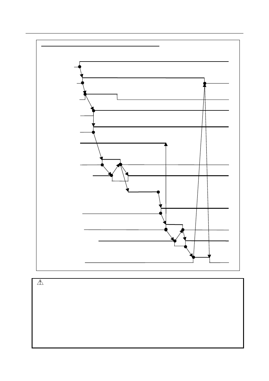
  Timing chart for spindle positioning (specification A) 


M code command 


Strobe signal 

   MF 

Spindle stop complete 

signals   SPSTPs 

Spindle position   

control 

Spindle unclamp signals 

   MSPOS 

Spindle enabled 


Spindle unclamp completion   

signals   SUCLPs 

Reference position return   

completion signals   *SUCPFs 

Spindle positioning rotation 


Spindle clamp signals 

   SCLPs 

Spindle clamp completion   

signals   *SCPFs 

Auxiliary function completion signal 

   FIN 


[Specification B: Bit 7 (IMB) of parameter No. 4950 = 1 ] 
<1>  Suppose that an M code is specified in a program. 
<2>  Auxiliary function code signal M00 to M31 is sent, and the auxiliary function strobe signal MF is set 

to 1 at the same time. This sending procedure is the same as for ordinary auxiliary functions. 

B-64693EN-1/01


10. SPINDLE SPEED FUNCTION


- 1541 - 

<3>  When strobe signal MF is set to 1, the PMC must read the code signal and perform corresponding 

processing. After completing the corresponding processing, the PMC sets spindle stop complete 
signal SPSTPs to 1 when the spindle is stopped. 

<4>  As soon as setting strobe signal MF to 1, the CNC checks whether spindle stop complete signal 

SPSTPs is set to 1. When the SPSTPs signal is set to 1, the CNC switches the spindle control mode 
from the spindle rotation mode to spindle positioning mode, and sets spindle positioning mode 
signal MSPOSs to 1. 

<5>  The CNC sets spindle unclamp signal SUCLPs to 1. 
<6>  When spindle unclamp signal SUCLPs is set to 1, the PMC unclamps the spindle, and when 

unclamping of the spindle is completed, the PMC sets spindle unclamp completion signal *SUCPFs 
to 0. 

<7>  When spindle unclamp completion signal *SUCPFs is set to 0, the CNC sets spindle unclamp signal 

SUCLPs to 0 to post that the CNC has received the *SUCPFs signal. 

<8>  When spindle unclamp signal SUCLPs is set to 0, the PMC sets spindle unclamp completion signal 

*SUCPFs to 1. 

<9>  After setting the SUCLPs signal to 0, the CNC rotates the spindle, makes a movement as specified, 

then stops the spindle. 

<10>The CNC sets spindle clamp signal SCLPs to 1. 
<11>When spindle clamp signal SCLPs is set to 1, the PMC clamps the spindle mechanically with a 

device such as a clutch or shot pin as necessary. After completing the clamping operation, the PMC 
sets spindle clamp completion signal *SCLPFs to 0. 

<12>When spindle clamp completion signal *SCLPs is set to 0, the CNC sets spindle clamp signal 

SCLPs to 0 to post that the CNC has received *SCLPFs. The CNC sets the SCLPs signal to 0, and 
switches the spindle control mode from the spindle positioning mode to spindle rotation mode at the 
same time. The CNC sets spindle positioning mode signal MSPOSs to 0. 

<13>When spindle clamp signal SCLPs is set to 0, the PMC sets spindle clamp completion signal 

*SCLPFs to 1. 

<14>Finally, the PMC sets completion signal FIN to 1 for auxiliary function strobe signal MF. In 

response to this, the CNC sets the MF signal to 0. Then, the PMC sets the FIN signal to 0. 

10. SPINDLE SPEED FUNCTION


B-64693EN-1/01


- 1542 - 


  Timing chart for spindle positioning (specification B) 


M code command 


Strobe signal 

   MF 

Spindle stop complete 

signals   SPSTPs 

Spindle position control 


Spindle positioning mode 

signals  MSPOS 

Spindle enabled 


Spindle unclamp signals 

   SUCLPs 

Spindle unclamp completion   

signals   *SUCPFs 

Spindle rotation 


Spindle clamp signals 

   SCLPs 

Spindle clamp   

completion signals   *SCPFs 

Auxiliary function completion signal 

   FIN 


  Canceling spindle positioning 

To cancel the spindle positioning mode and enter the spindle rotation mode again, use an M code for 
canceling the spindle positioning mode. 
Set the M code in parameter No. 4961 in advance. 
 
<1>  Suppose that an M code is specified in a program. 
<2>  Auxiliary function code signal M00 to M31 is sent, and the auxiliary function strobe signal MF is set 

to 1 at the same time. This sending procedure is the same as for ordinary auxiliary functions. 

<3>  When strobe signal MF is set to 1, the PMC must read the code signal and perform corresponding 

processing. After completing the corresponding processing, the PMC sets spindle stop complete 
signal SPSTPs to 1 when the spindle is stopped. 

B-64693EN-1/01


10. SPINDLE SPEED FUNCTION


- 1543 - 

<4>  As soon as setting strobe signal MF to 1, the CNC checks whether spindle stop complete signal 

SPSTPs is set to 1. When the SPSTPs signal is set to 1, the CNC sets spindle unclamp signal 
SUCLPs to 1. 

<5>  When spindle unclamp signal SUCLPs is set to 1, the PMC unclamps the spindle, and when 

unclamping of the spindle is completed, the PMC sets spindle unclamp completion signal *SUCPFs 
to 0. 

<6>  When spindle unclamp completion signal *SUCPFs is set to 0, the CNC sets spindle unclamp signal 

SUCLPs to 0 to post that the CNC has received the *SUCPFs signal. As soon as setting the SUCLPs 
signal to 0, the CNC switches the spindle control mode from the spindle positioning mode to spindle 
rotation mode. The CNC sets spindle positioning mode signal MSPOSs to 0. 

<7>  When spindle unclamp signal SUCLPs is set to 0, the PMC sets spindle unclamp completion signal 

*SUCPFs to 1. 

<8>  Finally, the PMC sets completion signal FIN to 1 for auxiliary function strobe signal MF. In 

response to this, the CNC sets the MF signal to 0. Then, the PMC sets the FIN signal to 0. 


  Timing chart for canceling spindle positioning mode 


M code command 


Strobe signal 

signals   MF 

Spindle stop complete 

signals 


SPSTPs 

Spindle position   

control 

Spindle positioning 

mode signals MSPOS 


Spindle unclamp signals 

   SUCLPs 

Spindle unclamp completion   

signals   *SUCPFs 


Auxiliary function   

completion signal   FIN 


10. SPINDLE SPEED FUNCTION


B-64693EN-1/01


- 1544 - 

Parameter 

Major related parameters are described below. 


#7 

#6 

#5 

#4 

#3 

#2 

#1 

#0 

1005 


ZRNx 


[Input type]  Parameter input 


[Data type]  Bit axis 


#0  ZRNx

  If a move command other than G28 is specified by automatic operation when no 

reference position return is performed yet after the power is turned on:   
0: 

The alarm PS0224, "ZERO RETURN NOT FINISHED" is issued. 

1: 

Operation is performed without issuing an alarm. 


NOTE 

1  The state in which a reference position has not been established 

refers to the following state: 

-  When an absolute position detector is not used and reference 

position return has not been performed even once after power-up 

-  When an absolute position detector is used and the association of 

the machine position with the position detected with the absolute 
position detector has not been completed (See the description of 
bit 4 (APZx) of parameter No. 1815.) 

2  When the Cs axis coordinates are to be set up, set ZRN to 0. 


#7 

#6 

#5 

#4 

#3 

#2 

#1 

#0 

1006 


ZMIx 


DIAx 


ROSx 

ROTx 


[Input type]  Parameter input 


[Data type]  Bit axis 


NOTE 


When at least one of these parameters is set, the power must be 
turned off before operation is continued. 


#0  ROTx

  Setting linear or rotation axis. 


#1  ROSx 


ROSx 

ROTx 

Meaning 

Linear axis 
(1)  Inch/metric conversion is done. 
(2)  All coordinate values are linear axis type. (Is not rounded in 0 to 360

°

(3)  Stored pitch error compensation is linear axis type (Refer to parameter No. 

3624) 

Rotary axis (A type) 
(1)  Inch/metric conversion is not done. 
(2)  Machine coordinate values are rounded in 0 to 360

°

. Absolute coordinate 

values are rounded or not rounded by bits 0 (ROAx) and 2 (RRLx) of 
parameter No. 1008. 

(3)  Stored pitch error compensation is the rotation type. (Refer to parameter 

No. 3624) 

(4)  Automatic reference position return (G28, G30) is done in the reference 

position return direction and the move amount does not exceed one 
rotation. 

B-64693EN-1/01


10. SPINDLE SPEED FUNCTION


- 1545 - 

ROSx 

ROTx 

Meaning 

Rotary axis (B type) 
(1)  Inch/metric conversion is not done. 
(2)  Machine coordinate values, absolute coordinate values and relative 

coordinate values are linear axis type. (Is not rounded in 0 to 360

°

). 

(3)  Stored pitch error compensation is linear axis type (Refer to parameter No. 

3624) 

(4)  Cannot be used with the rotary axis roll-over function and the index table 

indexing function (M series) 

Except for the 

above. 

Setting is invalid (unused) 


#3  DIAx

  The move command for each axis is based on: 

0: 

Radius specification 

1: 

Diameter specification 


#5  ZMIx

  The direction of manual reference position return is: 

0: 

+ direction 

1: 

- direction 


#7 

#6 

#5 

#4 

#3 

#2 

#1 

#0 

1013 


ISCx 

ISAx 


[Input type]  Parameter input 


[Data type]  Bit axis 


NOTE 


When at least one of these parameters is set, the power must be 
turned off before operation is continued. 


#0  ISAx


#1  ISCx

  Increment system of each axis 


Increment system 

Bit 1 (ISC) 

Bit 0 (ISA) 

IS-A 

IS-B 

IS-C 

 
IS-B is specified for the spindle positioning axis.Therefore, set ISA to ISE to 0. 
 

1022 


Setting of each axis in the basic coordinate system 


[Input type]  Parameter input 


[Data type]  Byte axis 

[Valid data range]  0 to 7 

To determine a plane for circular interpolation, cutter compensation, and so forth (G17: 
Xp-Yp plane, G18: Zp-Xp plane, G19: Yp-Zp plane), specify which of the basic three 
axes (X, Y, and Z) is used for each control axis, or a parallel axis of which basic axis is 
used for each control axis. 
A basic axis (X, Y, or Z) can be specified only for one control axis. 
Two or more control axes can be set as parallel axes for the same basic axis. 

Setting 

Meaning 

Rotary axis (Neither the basic three axes nor a parallel axis ) 

X axis of the basic three axes 


Content      ..     196      197      198      199     ..