FANUC Series 0i-MODEL F Plus. CONNECTION MANUAL (FUNCTION) - page 177
 

  Index      Manuals     FANUC Series 0i-MODEL F Plus. CONNECTION MANUAL (FUNCTION) B-64693EN-1/01


Search            copyright infringement  


Content      ..     175      176      177      178     ..


FANUC Series 0i-MODEL F Plus. CONNECTION MANUAL (FUNCTION) - page 177


8. MULTI-PATH CONTROL


B-64693EN-1/01


- 1370 - 

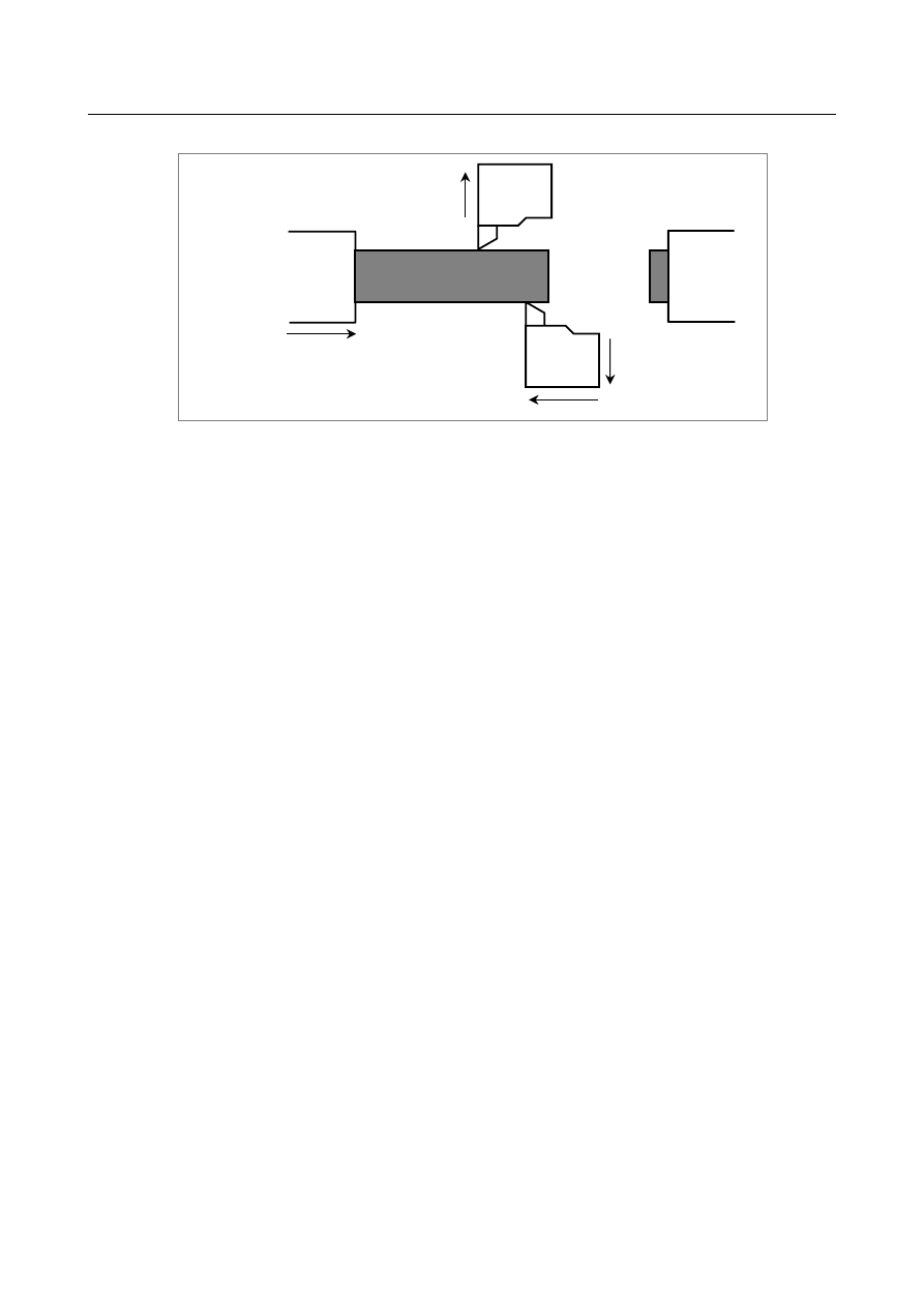
(b)  Z1-Z2 axis superimposed control 


The workpiece attached 
to spindle S1 is machined 
with path 1 (X1-Z1) and 
path 2 (X2-Z2). 
 

Z1 

Spindle S1 

Turret 1 
 

X1 

Turret 2 

Z2 

Spindle S2 

X2 


Fig. 8.7 (e) 

 
(2)  Parameter setting 

To superimpose the move command for the Z1 (master) axis on that of the Z2 (slave) axis, set 
parameter No. 8186z of path 2 to "102". 

Since the plus directions of the Z1 (master) and Z2 (slave) axes are opposite from each other, 
perform superimposed control with a mirror image applied. To do this, set bit 3 (OMRz) of 
parameter No. 8162 of path 2 to 1. 

 
(3)  Signal operation 

To start superimposed movement along the Z1 (master) axis and the Z2 (slave) axis, set signal 
OVLS2 <G1190.1> to "1". 

To cancel superimpose, set signal OVLS2 <G1190.1> to "0". 

When an emergency stop, NC reset, or alarm occurs, set signal OVLS2 <G1190.1> to "0". 

Set signals other than signal OVLS2 <G1190.1> to "0". 


B-64693EN-1/01


8. MULTI-PATH CONTROL


- 1371 - 

(4)  Program example 


Path 1 


Path 2 

N1000    . . . 


N2000    . . . 

N1010  M200 P12 ; 

N2010  M200 P12 ; 


N2020  M55 ; 


N1030  M201 P12 ; 

N2030  M201 P12 ; 


N2040  T0414 ; 


N1050  S1000 M3 ; 
N1060  G0 X20.0 Z15.0 ;  N2060 G0 X18.0 Z120.0 ; 


N1070  G1 F0.5 W-8.0 ;  N2070 G1 F0.1 W5.0 ; 
 
 
N1080  . . . 


N2080  . . . 

N1010  M200 P12 ; 

N2010  M200 P12 ; 


N2100  M56 ; 


N1010  M201 P12 ; 

N2010  M201 P12 ; 

N1120  . . . 


N2120  . . . 

 
where 
M55 is an M code to start superimposed control, and 
M56 is an M code to cancel superimposed control. 

Independent machining of each path 
Waiting 
Start of superimposed control from the   
Z1 axis to the Z2 axis 
 
Waiting 
Selection of a superimposed control tool and 
setting of an offset 

Waiting 
End of superimposed control 
 
 
Waiting 
Independent machining of each path 
 

Machining by turret 1 and turret2 


  CAUTION 


If performing constant surface speed control, you must determine the spindle 
command in which path is currently effective to spindle S1. 


NOTE 


Input the speed of spindle S1 (feedback pulses from the position coder) to both 
paths 1 and 2. 


Troubleshooting 

1. 

Unable to start superimposed control. (No alarm occurs.) 
(1)  The correct superimposed control have not been set up. 

  To perform superimposed control, you must set up the correct 

(2)  The superimposed control axis selection signals OVLS1 to OVLS8 <Gn190> is not set to "1". 

  Superimposed control starts when the superimposed control axis selection signals OVLS1 

to OVLS8 <Gn190> is changed from "0" to "1". After superimposed control ends due to a 
reset or alarm, merely canceling the reset or alarm cause will not cause superimposed 
control to restart. After canceling the reset or alarm cause, you must make the signal rise 
again. 

(3)  The axis number of the axis subject to superimposed control is not set in the appropriate 

parameter. 

  To perform superimposed control, set the axis number of the master axis in parameter No. 

8186. 

8. MULTI-PATH CONTROL


B-64693EN-1/01


- 1372 - 

(4)  Superimposed control cannot be started if the NC unit is one of the following states: 

Emergency stop 

Reset 

Servo alarm   

Alarm PW0000 

Alarm related to superimposed control 


Superimposed control cannot be started, either, if the axis on which superimposed control is to 
start is either of the following states: 

Servo off 

Overtravel 

 
2. 

An attempt to raise a superimposed start signal results in PS alarm. 
(1)  An attempt is made to use an axis already under superimposed control for another 

superimposed signal operation. (Alarm PS0362) 

  You cannot use a single axis for a combination of multiple superimposed control 

operations. 

(2)  The axis number set in a parameter is greater than the number of controllable axes. (Alarm 

PS0360) 

  The number of the superimposed master axis and that of the interchanging axis subject to 

superimposed control must not exceed the number of axes controllable in the remote path 
(or the local path if you are to perform superimposed control in that path). 

(3)  The tool is moving along the axis that you want to control. (Alarm PS0361) 

  At the start of superimposed control, the tool must be stopped on the axis subject to that 

control. That the tool is stopped on an axis means that the speed specified after 
acceleration/deceleration is zero. 

(4)  An axis on which you want to perform superimposed control belongs to another machine group. 

(Alarm PS0360) 

  The axes on which you want to perform superimposed control must be of the same 

machine group. 

 
3. 

An attempt to cancel superimposed control results in alarm PS0361. 
(1)  The tool is moving along the axis on which the control you want to cancel. 

  To cancel superimposed control, the tool must be stopped on the axis on which to cancel it. 

That the tool is stopped on an axis means that the  speed specified after 
acceleration/deceleration is zero. Before canceling, make sure that the axis moving signals 
MV1 to MV8 <Fn102> has changed to "0". 


4. 

In superimposed control, the amount of travel is not correct. 
(1)  The master and slave axes differ in diameter/radius specification or in inch/millimeter setting. 

  In superimposed control, diameter/radius conversion or inch/millimeter conversion is not 

performed between master and slave. The master and slave must match in least command 
increment. 

 
5. 

In superimposed control, alarm PS0363 occurs. 
(1)  In superimposed control, a reference position return is performed on the slave axis. 

  No reference position return can be performed on the slave axis under superimposed 

control. 


B-64693EN-1/01


8. MULTI-PATH CONTROL


- 1373 - 

6. 

Superimposed control is canceled although the superimposed control axis selection signals OVLS1 
to OVLS8 <Gn190> is not changed from "1" to "0". 

  In superimposed control, superimposed control will be automatically canceled if at least either 

of the paths enters one of the following states: 

Emergency stop 

Reset 

Servo alarm 

Alarm PW0000 

Alarm related to superimposed control 


In addition, if at least one of the axes on which superimposed control is in progress enters either 
of the following states: 

Servo off 

Overtravel 

 
7. 

Alarm DS1933 occurs. 

  In superimposed control, alarm DS1933 occurs if at least one path enters one of the following 

states: 

Emergency stop 

Servo off 

Servo alarm 


After canceling the emergency stop, after canceling servo off, or after restoring from the servo 
alarm, first perform a reference position return or coordinate system setting and then start 
superimposed control. 


8.8 

SUPERIMPOSED CONTROL(WITH SPEED CONTROL) 

For a slave axis under superimposed control, a travel distance specified by the program for the master 
axis path is added to a travel distance specified by the program for the slave axis path. So, the actual 
speed on a slave axis is excessively higher than ordinary speed ("ordinary speed" means a speed such as a 
parameter-set rapid traverse rate). 
To prevent this, feedrates and a linear acceleration/deceleration time constant in rapid traverse can be set 
for use only during superimposed control with this function. 
 
The parameters for feedrates and a time constant usable only during superimposed control are indicated 
below. 

-    Rapid traverse rate 

Parameter No. 8190 

F0 velocity of rapid traverse override 

Parameter No. 8191 

Linear acceleration/deceleration time constant in rapid traverse 

Parameter No. 8192 

Maximum cutting feedrate 

Parameter No. 8194 

(- 

Manual rapid traverse rate 

Value of parameter No. 8190 or 1424, 
whichever smaller) 

 
During superimposed control, each of the master and slave axes uses these separately set parameters. 
Set proper values, considering a feedrate after addition of a travel distance. 
 

Parameter 

8190 


Rapid traverse rate of an axis under superimposed control 


[Input type]  Parameter input 


[Data type]  Real axis 


[Unit of data]  mm/min, inch/min, deg/min (machine unit) 

[Min. unit of data]  Depend on the increment system of the applied axis 
[Valid data range]  Refer to standard parameter setting table (C) (See “PREFACE” in this manual.) 

(When the increment system is IS-B, 0 to +999000.0) 

8. MULTI-PATH CONTROL


B-64693EN-1/01


- 1374 - 

Set a rapid traverse rate for each of the axes when the rapid traverse override of the axes 
(master and slave axes) under superimposed control is 100%. The manual rapid traverse 
rate set in this parameter or the manual rapid traverse rate set in parameter No. 1424, 
whichever smaller, is used. 
If this parameter is set to 0, the normal rapid traverse rate (parameter No. 1420) is used. 
 

8191 


F0 velocity of rapid traverse override of an axis under superimposed control 


[Input type]  Parameter input 


[Data type]  Real axis 


[Unit of data]  mm/min, inch/min, deg/min (machine unit) 

[Min. unit of data]  Depend on the increment system of the applied axis 
[Valid data range]  Refer to standard parameter setting table (C) (See “PREFACE” in this manual.) 

(When the increment system is IS-B, 0 to +999000.0) 
Set the F0 velocity of rapid traverse override of an axis under superimposed control (each 
of the master and slave axes). 
If this parameter is set to 0, the F0 velocity of rapid traverse override in normal operation 
(parameter No. 1421) is used. 
 

8192 


Linear acceleration/deceleration time constant in rapid traverse of an axis under superimposed control 


[Input type]  Parameter input 


[Data type]  Word axis 


[Unit of data]  msec 

[Valid data range]  0 to 4000 

This parameter specifies the linear acceleration/deceleration time constant in rapid 
traverse for each of the axes (master and slave axes) under superimposed control. 
 

8194 


Maximum cutting feedrate in superimposed control 


[Input type]  Parameter input 


[Data type]  Real axis 


[Unit of data]  mm/min, inch/min, deg/min (machine unit) 

[Min. unit of data]  Depend on the increment system of the applied axis 
[Valid data range]  Refer to standard parameter setting table (C) (See “PREFACE” in this manual.) 

(When the increment system is IS-B, 0 to +999000.0) 
Set the maximum cutting feedrate that can be applied under superimposed control. 
If this parameter is set to 0, the maximum cutting feedrate in normal operation (parameter 
No. 1430) is used. 
 

B-64693EN-1/01


8. MULTI-PATH CONTROL


- 1375 - 

8.9 

SYNCHRONOUS, COMPOSITE, AND SUPERIMPOSED 
CONTROL BY PROGRAM COMMAND 

Overview 

Synchronous control, composite control, and superimposed control can be started or canceled using a 
program command instead of a DI signal. 
Synchronous control, composite control, and superimposed control based on a DI signal is also possible. 
For the basic operations of synchronous control, composite control, and superimposed control, see 
Section "SYNCHRONOUS / COMPOSITE CONTROL", and "SUPERIMPOSED CONTROL". 
 

Format 

G51.4  P_ Q_  (L_) ;  Start synchronous control (L_ can be omitted) 

G50.4  Q_ ; 

Cancel synchronous control 

 
P:  Number to identify synchronous master axis 
Q: Number to identify synchronous slave axis 
L:  Parking state command 
 

1: Master parking (slave parking cancel) 


2: Slave parking (master parking cancel) 


0: No parking (parking cancel) 


(When L is omitted, the specification of L0 is assumed.) 


G51.5    P_ Q_ ; 

Start composite control 

G50.5    P_ Q_ ; 

Cancel composite control 

 
P:  Number to identify composite axis 1 
Q: Number to identify composite axis 2 
 

G51.6    P_ Q_ ; 

Start superimposed control 

G50.6  Q_ ; 

Cancel superimposed control   

 
P:  Number to identify superimposed master axis 
Q: Number to identify superimposed slave axis 
 
Identification numbers are unique values that set into parameter No. 12600 in order to 
identify each axes. 


NOTE 

1  These commands are one-shot G code. 
2  These commands must be specified in a single block. 
3  When P,Q or L command is out of range, the alarm PS5339"ILLEGAL FORMAT 

COMMAND IS EXECUTED IN SYNC/MIX/OVL CONTROL." occurs. 


Explanation 

  - 

Synchronous control 

Synchronous control is exercised by the G51.4/G50.4 commands instead of the synchronous control axis 
selection signals (SYNC1 to SYNC8<Gn138.0-7>, n=0 to 9). 
 

8. MULTI-PATH CONTROL


B-64693EN-1/01


- 1376 - 

  - 

Composite control 

Composite control is exercised by the G51.5/G50.5 commands instead of the composite control axis 
change selection signals (MIX1 to MIX8<Gn128.0-7>, n=0 to 9). 
 

  - 

Superimposed control 

Superimposed control is exercised by the G51.6/G50.6 commands instead of the superimposed control 
axis selection signals (OVLS1 to OVLS8<Gn190.0-7>, n=0 to 9). 
 

Parameter 

12600 


Identification Number for synchronous, composite, and superimposed control by program command 


[Input type]  Parameter input 


[Data type]  Word axis 

[Valid data range]  0,1 to 32767 

Set identification numbers that can be specified with P,Q addresses. 
The axis whose identification number is 0 cannot become under synchronous, composite, 
and superimposed control by program command. 
The same identification number cannot be set to two or more axes through all paths. 
When the same identification number is set, alarm PS5339 occurs at 
G50.4/G50.5/G50.6/G51.4/G51.5/G51.6 commands. 
 

Alarm and message 

Number 

Message 

Description 

PS5339 

ILLEGAL FORMAT COMMAND IS 
EXECUTED IN SYNC/MIX/OVL 
CONTROL. 

1.  The value of P, Q, or L specified by 

G51.4/G50.4/G51.5/G50.5/G51.6/G50.6 is invalid. 

2.  A duplicate value is specified by parameter No. 12600. 


Note 

NOTE 

1  If a G code (G50.4/G50.5/G50.6) for canceling synchronous, composite, or 

superimposed control based on a program command is specified using a DI 
signal for an axis under synchronous, composite, or superimposed control, 
synchronous, composite, or superimposed control is canceled. 

2  If the synchronous control axis selection signal/composite control axis change 

selection signal/superimposed control axis selection signal is set to 1 from 0 and 
to 0 from 1 for an axis under synchronous, composite, or superimposed control 
based on a program command, synchronous, composite, or superimposed 
control is canceled. 
For an axis under synchronous, composite, or superimposed control based on a 
program command, if the synchronous control axis selection signal/composite 
control axis change selection signal/superimposed control axis selection signal is 
set to 1 from 0, the state of synchronous, composite, or superimposed control 
isn't influenced.   


B-64693EN-1/01


8. MULTI-PATH CONTROL


- 1377 - 

8.10 

SUPERIMPOSED CONTROL AVAILABLE IN THE AI 
CONTOUR CONTROL MODE 

Overview 

This function enables superimposed control in the AI contour control mode. 
Moreover, advance preview feed forward function becomes effective by the AI contour control when the 
parameters about advance preview feed forward function are set. 
 

Explanation 

To use superimposed control and AI contour control simultaneously during automatic operation, it is 
necessary to set the AI contour control permission signal OVLN to 1 and place the CNC in the advanced 
superimposition mode. 
 

NOTE 

1  To use superimposed control in the AI contour control mode, set the AI contour 

control permission signal for the master and slave axis paths to 1. If 
superimposed control is started when the advanced superimposition mode is off, 
AI contour control is turned off. Moreover, lowering of the precision or the shock 
might occur when the advanced superimposition mode for the one of paths is off. 

2  Setting the AI contour control permission signal to 1 immediately after power-on 

can place the master and slave axis paths in the advanced superimposition 
mode without specifying a superimposed control mode on command in the 
program. 

 
See the following example for the program sequence  for specifying M codes for the advanced 
superimposition mode and superimposed control. 
 
Program example) 
 

Path of master axis 

Path of slave axis 

M100P12; ----- Waiting 
M210; ----- Advanced superimposition mode on. (Note 1) 
 
M101P12; ----- Waiting 
G05.1Q1; ----- AI contour control mode on. (Note 2) 

M100P12; ----- Waiting 
M212; ----- Advanced superimposition mode on. 
M60; ----- Starts superimposed control. 
M101P12; ----- Waiting 
G05.1Q1; ----- AI contour control mode on. 

  : ------ Master axis move commands 


M102P12; ----- Waiting 
 
M211; ----- Advanced superimposition mode off. (Note 1) 
M103P12; ----- Waiting 


M102P12; ----- Waiting 
M61; ----- Cancels superimposed control. 
M213; ----- Advanced superimposition mode off. 
M103P12; ----- Waiting 


NOTE 

1  Turn the advanced superimposition mode on or off after canceling superimposed 

control for the slave path. 

2  The AI contour control mode can be turned on by setting bit 0 (SHP) of 

parameter No. 1604 to 1 instead of using G05.1Q1;. 


Content      ..     175      176      177      178     ..