FANUC Series 0i-MODEL F Plus. CONNECTION MANUAL (FUNCTION) - page 161
 

  Index      Manuals     FANUC Series 0i-MODEL F Plus. CONNECTION MANUAL (FUNCTION) B-64693EN-1/01


Search            copyright infringement  


Content      ..     159      160      161      162     ..


FANUC Series 0i-MODEL F Plus. CONNECTION MANUAL (FUNCTION) - page 161


B-64693EN-1/01


- 1242 - 

7. FEEDRATE CONTROL/ACCELERATION AND 

DECELERATION CONTROL 

  - 

Acceleration/deceleration before interpolation for rapid traverse in rigid 
tapping. 

When look-ahead acceleration/deceleration before interpolation for rapid traverse is valid, if the setting of 
look-ahead acceleration/deceleration before interpolation for rapid traverse in rigid tapping is enabled (Bit 
5 (RRB) of parameter No.11240 is set to 1), look-ahead acceleration/deceleration before interpolation for 
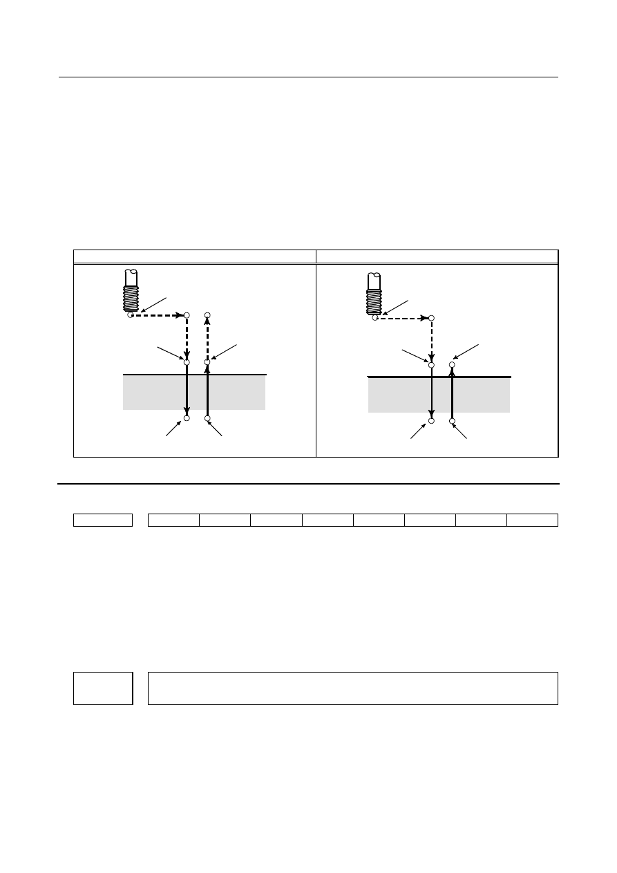
rapid traverse in rigid tapping  is valid.  (Rapid traverse in rigid tapping is the motion of dotted line in 
Fig.7.2.9 .) 
However,  the  specification of acceleration/deceleration in the following functions follows the 
specification of each function. 

Optimum Acceleration/Deceleration for Rigid Tapping 

Rigid Tapping with Servo Motor 


G84 (G98) 

G84 (G99) 

Initial level

Point R

Spindle
stop

Spindle CW

Point Z

P

Point R level

Operation 2

Operation 1

Operation 6

Operation 3

Operation 4

Operation 5

Spindle stop

Spindle CCW

Spindle stop

P


Point R

Spindle CW

Point Z

P

Point R level

Spindle stop

Spindle CCW

Spindle stop

Spindle stop

P


Fig.7.2.9  Rigid tapping command 


Parameter 


#7 

#6 

#5 

#4 

#3 

#2 

#1 

#0 

1401 


LRP 


[Input type]  Parameter input 


[Data type]  Bit path 


#1  LRP

  Positioning (G00) 

0: 

Positioning is performed with non-linear type positioning so that the tool moves 
along each axis independently at rapid traverse.   

1: 

Positioning is performed with linear interpolation so that the tool moves in a straight 
line. 

When using 3-dimensional coordinate system conversion, set this parameter to 1. 
 

1671 


Maximum allowable acceleration rate in acceleration/deceleration before interpolation for linear rapid 

traverse for each axis, or maximum allowable reference acceleration rate in optimum torque 

acceleration/deceleration 


[Input type]  Parameter input 


[Data type]  Real axis 


[Unit of data]  mm/sec

2

, inch/sec

2

, deg/sec

2

 (machine unit) 


[Min. unit of data]  Depend on the increment system of the applied axis 


[Valid data range]  Refer to the standard parameter setting table (D) 

(When the machine system is metric system, 0.0 to +100000.0. When the machine system 
is inch system, machine, 0.0 to +10000.0.) 

B-64693EN-1/01


- 1243 - 

7. FEEDRATE CONTROL/ACCELERATION 

AND DECELERATION CONTROL 

(1)  Set a maximum allowable acceleration rate in look-ahead acceleration/ deceleration 

before interpolation for linear rapid traverse. 


If a value greater than 100000.0, the value is clamped to 100000.0. 


If 0 is set, the specification of the following is assumed: 


  1000.0 mm/sec

2


  100.0 inch/sec

2


  100.0 degrees/sec

2


If 0 is specified for all axes, however, look-ahead  acceleration/deceleration before 
interpolation is not performed. 

(2)  Maximum allowable reference acceleration rate in optimum torque 

acceleration/deceleration 


1672 


Acceleration change time of bell-shaped acceleration/deceleration before interpolation for linear rapid 

traverse, or acceleration change time of bell-shaped acceleration/deceleration in optimum torque 

acceleration/deceleration 


[Input type]  Parameter input 


[Data type]  2-word path 


[Unit of data]  msec 


[Valid data range]  0 to 200 

(1)  Set an acceleration change time of bell-shaped acceleration/ deceleration for linear 

rapid traverse (time for changing from the state of constant feedrate (A) to the state 
of constant acceleration/deceleration (C) at the acceleration rate calculated from the 
acceleration rate set in parameter No. 1671: time of (B) in the figure below). 

(2)  Set an acceleration change time of bell-shaped acceleration/ deceleration in optimum 

torque acceleration/deceleration (time for changing from the state of constant 
feedrate (A) to the state of acceleration/deceleration (C) at the acceleration rate 
calculated from optimum torque acceleration/deceleration: time of (B) in the figure). 

Feedrate in tangent direction

Maximum  acceleration rate not exceeding
maximum allowable acceleration rate set by
parameter No. 1671 for each axis is
automatically calculated.

Time set by parameter No. 1672

(A)

(B)

(B)

(B)

(B)

(A)

(A)

(C)

(C)


#7 

#6 

#5 

#4 

#3 

#2 

#1 

#0 

11240 


RRB 

ARB 


[Input type]  Parameter input 


[Data type]  Bit path 


#4  ARB

  Look-ahead  acceleration/deceleration before interpolation for rapid traverse in AICC 

mode off is: 
0: 

Disabled. 

1: 

Enabled. 


B-64693EN-1/01


- 1244 - 

7. FEEDRATE CONTROL/ACCELERATION AND 

DECELERATION CONTROL 

NOTE 


This parameter is enabled when the parameters for which 
look-ahead acceleration/deceleration before interpolation for rapid 
traverse is enabled are set. (Refer to bit 5 (FRP) of parameter 
No.19501.) 


#5  RRB

  Look-ahead  acceleration/deceleration before interpolation for rapid traverse in rigid 

tapping is: 
0: 

Disabled. 

1: 

Enabled. 


NOTE 


This parameter is enabled when look-ahead 
acceleration/deceleration before interpolation for rapid traverse is 
valid. (Refer to bit 5 (FRP) of parameter No.19501.) 


11242 


Time constant of acceleration/deceleration after interpolation of acceleration/deceleration before 

interpolation in rapid traverse 


[Input type]  Parameter input 


[Data type]  Word axis 


[Unit of data]  msec 

[Valid data range]  0 to 4000 

This parameter is used for the time constant of look-ahead  acceleration/deceleration 
before interpolation in rapid traverse. 
Be sure to specify the same time constant value for all axes except for a special 
application. If different time constants are set, a correct linear line cannot be obtained. 


#7 

#6 

#5 

#4 

#3 

#2 

#1 

#0 

19501 


FRP 


[Input type]  Parameter input 


[Data type]  Bit path 


#5  FRP

  Linear rapid traverse is: 

0: 

Acceleration/deceleration after interpolation 

1: 

Look-ahead acceleration/deceleration before interpolation 

Set a maximum allowable acceleration rate for each axis in parameter No. 1671. 

When using look-ahead bell-shaped acceleration/deceleration before interpolation, set an 
acceleration rate change time in parameter No. 1672. 

 
When this parameter is set to 1, look-ahead acceleration/deceleration before interpolation 
is also applied to rapid traverse if all conditions below are satisfied. At this time, 
acceleration/deceleration after interpolation is not applied. 

Bit 1 (LRP) of parameter No. 1401 is set to 1: Linear interpolation type positioning 

A value other than 0 is set in parameter No. 1671 for an axis. 

The AI contour control mode is set. 

If all of these conditions are not satisfied, acceleration/deceleration after interpolation is 
applied. 


B-64693EN-1/01


- 1245 - 

7. FEEDRATE CONTROL/ACCELERATION 

AND DECELERATION CONTROL 

7.2.10 

Time constant of acceleration / deceleration after 
interpolation switching function by signal 

Overview 

Time constant of acceleration / deceleration after interpolation can be switched by input signal of PMC. 
 

Explanation 

In this function, time constant of acceleration / deceleration after interpolation  for rapid traverse and 
cutting feed can be switched by input signal of PMC.   
 

- Time constant of acceleration / deceleration after interpolation for rapid traverse 

switching 

A time constant of acceleration / deceleration after interpolation for rapid traverse can be switched  to 
either of the three following kinds by time constant of acceleration / deceleration after interpolation for 
rapid traverse switching signals RTC2, RTC3<Gn599.6, Gn599.7>. 
- The usual time constant for rapid traverse (Parameter Nos. 1620 and 1621) 
- The second time constant for rapid traverse (Parameter Nos. 1674 and 1675) 
- The third time constant for rapid traverse (Parameter Nos. 1676 and 1677) 


Example of time chart for time constant of acceleration / deceleration after interpolation for rapid traverse 
switching 


Confirm an effective parameter by time constant of acceleration / deceleration after interpolation for rapid 
traverse switching confirmation signal RTC2O, RTC3O. 


Time constant of acceleration / 
deceleration after interpolation 
for rapid traverse switching signal 
RTC2<Gn599.6> 

Time constant of acceleration / 
deceleration after interpolation 
for rapid traverse switching signal 
RTC3<Gn599.7> 

Time constant of acceleration / 
deceleration after interpolation 
for rapid traverse switching 
confirmation signal RTC2O<Fn599.6> 

Time constant of acceleration / 
deceleration after interpolation 
for rapid traverse switching 
confirmation signal RTC3O<Fn599.7> 

No.1620 
No.1621 

No.1674 
No.1675 

No.1620 
No.1621 

No.1676 
No.1677 

No.1620 
No.1621 

Switching state of the parameter 
of a valid time constant 


B-64693EN-1/01


- 1246 - 

7. FEEDRATE CONTROL/ACCELERATION AND 

DECELERATION CONTROL 

- Time constant of acceleration / deceleration after interpolation for cutting feed 

switching 

A time constant of acceleration / deceleration after interpolation for cutting feed can be switched to either 
of the three following kinds by time constant of acceleration / deceleration after interpolation for cutting 
feed switching signals CTC2, CTC3<Gn599.4, Gn599.5>. 
- The usual time constant for cutting feed (Parameter No. 1622) 
- The second time constant for cutting feed (Parameter No. 1678) 
- The third time constant for cutting feed (Parameter No. 1679) 
 
Example of time chart for time constant of acceleration / deceleration after interpolation for cutting feed 
switching 


Confirm an effective parameter  by time constant of acceleration / deceleration after interpolation for 
cutting feed switching confirmation signal CTC2O, CTC3O. 
 

NOTE 

1)  If -1 is set to parameters Nos. 1674 or 1676 or a value not within the valid data range is specified in 

these parameters, the second or the third time constant of acceleration / deceleration after interpolation 
for rapid traverse is invalid in its axis. 

2)  If -1 is set to parameters Nos. 1678 or 1679 or a value not within the valid data range is specified in 

these parameters, the second or the third time constant of acceleration / deceleration after interpolation 
for cutting feed is invalid in its axis. 

3)  To  switch a time constant of acceleration / deceleration after interpolation, all the  valid  axes should 

stop.  When the axis has not stopped,  the time constant is switched at  the  next  program block  after 
stopping all the valid axes. 

4)  When an axis has been moved to other path by flexible path axis assignment function, a time constant 

of acceleration / deceleration after interpolation is switched by RTC2, RTC3, CTC2 and CTC3 of the 
path after moving. 

5)  A  slave axis of synchronous control is used  the same kind of acceleration / deceleration after 

interpolation as a master axis. However, as for the time constant, each one is used. When the master 
axis is a valid axis for this function, and the slave axis is an invalid axis, as for the time constant of the 
slave axis, the usual time constant is used. 

Time constant of acceleration / 
deceleration after interpolation 
for cutting feed switching signal 
CTC2<Gn599.4> 

Time constant of acceleration / 
deceleration after interpolation 
for cutting feed switching signal 
CTC3<Gn599.5> 


Time constant of acceleration / 
deceleration after interpolation 
for cutting feed switching 
confirmation signal CTC2O<Fn599.4> 

Time constant of acceleration / 
deceleration after interpolation 
for cutting feed switching   
confirmation signal CTC3O<Fn599.5> 

No.1622 

No.1678 

No.1622 

No.1679 

No.1622 

Switching state of the parameter 
of a valid time constant 

B-64693EN-1/01


- 1247 - 

7. FEEDRATE CONTROL/ACCELERATION 

AND DECELERATION CONTROL 

6)  A  movement  axis of composite  control  is used  the same kind of acceleration / deceleration after 

interpolation as a  specified  axis.  However, as for  the time constant, each one is used.  When the 
specified axis is a valid axis for this function, and the movement axis is an invalid axis, as for the time 
constant of the movement axis, the usual time constant is used. 

 
7)  In the following cases, a time constant for this function is invalid. 

A time constant of acceleration / deceleration after interpolation for manual handle retrace is valid 


8)  In the following cases, a time constant for rapid traverse for this function is invalid. 

As for the axes (a master axis and a slave axis) in superimposed control (with speed control) 

A  time constant of acceleration / deceleration after interpolation for positioning by optimum 
accelerations is valid 

Acceleration / deceleration before interpolation for rapid traverse of AI contour control is valid 

 
9)  In the following cases, a time constant for cutting feed for this function is invalid. 

A time constant of acceleration / deceleration after interpolation for the skip is valid 

A time constant of acceleration / deceleration after interpolation for rigid tapping is valid 

A time constant of acceleration / deceleration after interpolation for spindle control with servo     
motor is valid 

A time constant of exponential  acceleration / deceleration after interpolation in cutting feed for 
PMC axis control is valid 

Acceleration / deceleration before interpolation of AI contour control is valid 


7.2.10.1 

Time constant of acceleration/deceleration after interpolation 
in the mode of acceleration/deceleration before interpolation 
switching function by PMC signal 

Outline 

A time constant of acceleration/deceleration after interpolation in the mode of acceleration/deceleration 
before interpolation can be switched by PMC signal. 
 

Explanation 

In this function, the following time constant can be switched by PMC signal. 

-


Time constant of acceleration/deceleration after interpolation of acceleration/deceleration before 

interpolation in rapid traverse 

-


Time constant of acceleration/deceleration after cutting feed interpolation in the 

acceleration/deceleration before interpolation mode 


- Time constant of acceleration/deceleration after interpolation of 
acceleration/deceleration before interpolation in rapid traverse switching 

When parameter BRT(No.25750#0) is set to 1, a time constant of acceleration/deceleration after 
interpolation of acceleration/deceleration before interpolation in rapid traverse can be switched to either 
of the following three parameters  by time constant of acceleration/deceleration after interpolation for 
rapid traverse switching signals RTC2, RTC3<Gn599.6, Gn599.7>. 
Set  parameter No. 11242 to a value from 1 to 4000,  when executing “Time constant of 
acceleration/deceleration after interpolation of acceleration/deceleration before interpolation in rapid 
traverse switching”. 
-  The time constant of acceleration/deceleration after interpolation of acceleration/deceleration before 
interpolation in rapid traverse   
(Parameter No. 11242) 
-  The second time constant of acceleration/deceleration after interpolation of acceleration/deceleration 
before interpolation in rapid traverse   
(Parameter No. 25751) 


B-64693EN-1/01


- 1248 - 

7. FEEDRATE CONTROL/ACCELERATION AND 

DECELERATION CONTROL 

-  The third time constant  of acceleration/deceleration after interpolation of acceleration/deceleration 
before interpolation in rapid traverse   
(Parameter No. 25752) 


Example) 


- Time constant of acceleration/deceleration after cutting feed interpolation in 
the acceleration/deceleration before interpolation mode switching 

When parameter BCT(No.25750#1) is set to 1, a time constant of acceleration/deceleration after cutting 
feed interpolation in the acceleration/deceleration before interpolation mode can be switched to either of 
the following three parameters by time constant of acceleration/deceleration after interpolation for cutting 
feed switching signals CTC2, CTC3<Gn599.4, Gn599.5>. 
-  The time constant of acceleration/deceleration after cutting feed interpolation in the 
acceleration/deceleration before interpolation mode   
(Parameter No. 1769) 
-  The second time constant of acceleration/deceleration after cutting feed interpolation in the 
acceleration/deceleration before interpolation mode   
(Parameter No. 25753) 
-  The third time constant of acceleration/deceleration after cutting feed interpolation in the 
acceleration/deceleration before interpolation mode   
(Parameter No. 25754) 
 

Time constant of acceleration/ 
deceleration after interpolation 
for rapid traverse switching signal 
RTC2<Gn599.6> 

Time constant of acceleration/ 
deceleration after interpolation 
for rapid traverse switching signal 
RTC3<Gn599.7> 

Time constant of acceleration/ 
deceleration after interpolation 
for rapid traverse switching 
confirmation signal 
RTC2O<Fn599.6> 

Time constant of acceleration/ 
deceleration after interpolation 
for rapid traverse switching 
confirmation signal 
RTC3O<Fn599.7> 

No.11242 

State of a valid time constant 

No.25751 

No.11242 

No.25752 

No.11242 

B-64693EN-1/01


- 1249 - 

7. FEEDRATE CONTROL/ACCELERATION 

AND DECELERATION CONTROL 

Example) 


NOTE 

1)


In a function of not supporting time constant of acceleration/deceleration after interpolation of 

acceleration/deceleration before interpolation, this function is disabled. 

2)


When the parameter No.25751 or 25752 is set to -1, the second or third time constant of 

acceleration/deceleration after interpolation of acceleration/deceleration before interpolation in rapid 
traverse is disabled. 

3)


When the parameter No.25753 or 25754 is set to -1, the second or third time constant of 

acceleration/deceleration after cutting feed interpolation in the acceleration/deceleration before 
interpolation mode is disabled. 

4)


To switch a time constant of acceleration/deceleration after interpolation, all the valid axes must be 

stopped. When the axis has not stopped, the time constant is switched at the next program block after 
stopping all the valid axes. 

5)


When the parameters Nos.25751 to 25754 are changed during switching to a time constant of 

acceleration/deceleration after interpolation for this function, the time constant is also changed. 

6)


When an axis has been moved to other path by flexible path axis assignment function, a time constant 

of acceleration/deceleration after interpolation is switched by RTC2, RTC3, CTC2 and CTC3 of the 
path after moving. 

7)


A slave axis of the synchronous control is used the same kind of acceleration/deceleration after 

interpolation as a master axis. However, as for the time constant, each one is used. When the master 
axis is a valid axis for this function, and the slave axis is an invalid axis, as for the time constant of 
the slave axis, the usual time constant is used. 

8)


A movement axis of the composite control is used the same kind of acceleration/deceleration after 

interpolation as a specified axis. However, as for the time constant, each one is used. When the 
specified axis is a valid axis for this function, and the movement axis is an invalid axis, as for the 
time constant of the movement axis, the usual time constant is used. 

9)


In the following case, a time constant for this function is valid. 

-


A time constant of acceleration/deceleration after interpolation in the acceleration/deceleration 

before interpolation mode for the canned cycle for drilling is valid 

-


A time constant of acceleration/deceleration after interpolation in the acceleration/deceleration 

before interpolation mode for the automatic corner speed control is valid 

Time constant of acceleration/ 
deceleration after interpolation 
for cutting feed switching signal 
CTC2<Gn599.4> 

Time constant of acceleration/ 
deceleration after interpolation 
for cutting feed switching signal 
CTC3<Gn599.5> 

Time constant of acceleration/ 
deceleration after interpolation 
for cutting feed switching 
confirmation signal 
CTC2O<Fn599.4> 

Time constant of acceleration/ 
deceleration after interpolation 
for cutting feed switching   
confirmation signal 
CTC3O<Fn599.5> 

No.1769 

State of a valid time constant 

No.25753 

No.1769 

No.25754 

No.1769 


Content      ..     159      160      161      162     ..