FANUC Series 0i-MODEL F Plus. CONNECTION MANUAL (FUNCTION) - page 159
 

  Index      Manuals     FANUC Series 0i-MODEL F Plus. CONNECTION MANUAL (FUNCTION) B-64693EN-1/01


Search            copyright infringement  


Content      ..     157      158      159      160     ..


FANUC Series 0i-MODEL F Plus. CONNECTION MANUAL (FUNCTION) - page 159


B-64693EN-1/01


- 1226 - 

7. FEEDRATE CONTROL/ACCELERATION AND 

DECELERATION CONTROL 

Set the parameter of the gear to be used.   

Set parameters Nos. 11421 to 11424 to the maximum acceleration (rev/sec

2

). 

If these parameters are set to 0, a DS alarm DS1711,  “ILLEGAL ACC. PARAMETER (RIGID 
TAPPING OPTIMUM ACC/DEC)” is issued during execution. 

Since the spindle speed for P0 does not need to be set because it is 0

%

Since the spindle speed for P4 does not need to be set because it is 100

%

Set parameters Nos. 11429 to 11440 to the spindle speed for P1 to P3 as the ratio relative to the 
maximum spindle speed (parameters Nos. 5241 to 5244) in rigid tapping.   

Set parameters Nos. 11441 to 11480 to the allowable acceleration for P0 to P4 as the ratio relative to 
the maximum acceleration (parameters Nos. 11421 to 11424).   

Skip the acceleration setting point in which parameters Nos. 11429 to 11440 for spindle speed are 
set to 0 and treat a line connecting to the next acceleration setting point in which a nonzero value is 
set. 

When parameters Nos. 11441 to 11480 for allowable acceleration are set to 0, a value of 100

%

  is 

assumed.   


  - 

Expression indicating the relationship between torque and acceleration 

When the torque is 

(

)

m

N

T

  and the inertia is 

(

)

2

m

kg

J

, acceleration 

(

)

2

sec

rev

A

  is calculated by 

the following expression.   

(

)

(

)

(

)

p

2

2

m

kg

J

m

N

T

A

=


(

)

( )

(

) (

)

( )

p

2

sec

2

2

m

kg

J

m

m

kg

T

=


( )

(

)

J

T

=

p

2


  - 

Example of setting an acceleration pattern 

0

10

20

30

40

0

1000

2000

3000

4000

5000

6000

7000

8000

9000

10000

Spindle motor speed (min

-1

)

T

orq

u

e

 (

Nm)


Fig. 7.2.8 (d) Speed vs. torque characteristics of model 

a

i

I3/10000-B in the operational area of 30 minutes and 

S3 60%   

 
Structure 

The spindle and spindle motor are mutually connected directly.   

The spindle inertia is almost the same as the rotor inertia. 

The total inertial is double the rotor inertia. 

Model 

a

i

I3/10000-B motor 


Specification of the model 

a

i

I3/10000-B motor 

Rotor inertia 

0.0148

(

)

2

m

kg


Maximum torque 

34.3

(

)

m

N

   : Speed    0 to 1500 

(

)

1

min


Spindle inertia 

0.0148

(

)

2

m

kg


B-64693EN-1/01


- 1227 - 

7. FEEDRATE CONTROL/ACCELERATION 

AND DECELERATION CONTROL 

  The acceleration 

(

)

2

sec

rev

A

  at the maximum torque of 34.3

(

)

m

N

  is calculated from the above 

expression, which indicates the relationship between torque vs. acceleration. 


( )

(

)

(

)

2

sec

/

0148

.

0

0

.

2

2

3

.

34

rev

A

=

p


(

)

2

sec

426

.

184

rev

=


An example of setting the parameters for acceleration patterns is shown in Table 7.2.8 (b). 
Setting conditions   

The acceleration is constant for both acceleration and deceleration.   

The spindle and spindle motor is mutually connected directly (1:1). 

The maximum spindle speed is 6000 min

-1


Table 7.2.8 (b) Example of setting the parameters for acceleration patterns 


Parameter 

No. 

Setting 

value (unit) 

Remarks 

Maximum 
speed of 
spindle 

5241 

6000 

(min

-1


Maximum 
acceleration 

11421 

184 

(rev/sec

2

)   

Sets the maximum acceleration A. 

Spindle 
speed (P1) 

11429 

25 

(%) 

Since the rotation speed for a torque of 34.3 (Nm) is up to 1500 
(min

-1

), set P1 to 25% (1500 min

-1

).   

Spindle 
speed (P2) 

11430 

33 

(%) 

Since the torque drops linearly from 1500 (min

-1

) to 2000 (min

-1

), set 

P2 to 33% (1980 min

-1

). 

Spindle 
speed (P3 ) 

11431 

50 

(%) 

Since the torque drops linearly from 2000 (min

-1

) to 3000 (min

-1

), set 

P3 to 50% (3000 min

-1

). 

Acceleration 
(P0) 

11441 
11461 

100 

(%) 

Set the acceleration at a rotation speed of 0 to 100% (torque 34.3 
(Nm)). 

Acceleration 
(P1) 

11442 
11462 

100 

(%) 

Set the acceleration at the rotation speed of P1 to 100% (torque 
34.3 (Nm)).   

Acceleration 
(P2) 

11443 
11463 

72 

(%) 

Set the acceleration at the rotation speed of P2 to 72% (torque 25 
(Nm)).   

Acceleration 
(P3) 

11444 
11464 

43 

(%) 

Set the acceleration at the rotation speed of P3 to 43% (torque 15 
(Nm)). 

Acceleration 
(P4) 

11445 
11465 

23 

(%) 

Set the acceleration at the rotation speed of P4 to 23% (torque 8 
(Nm)).   

 
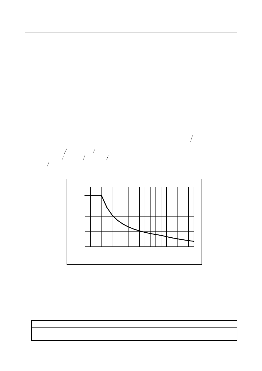
If the parameters are set as described in Table 7.2.8 (c), the acceleration pattern is assumed as shown in 
Fig. 7.2.8 (e). 
 

0

50

100

150

200

0

1000

2000

3000

4000

5000

6000

Spindle speed (min-1)

A

ccel

er

at

io

(r

ev

/s

ec

2

)


Fig. 7.2.8 (e) 

 
At P0, the rotation speed is 0 min

-1

 and the acceleration is 184 rev/sec

2

At P1, the rotation speed is 1500 min

-1

 and the acceleration is 184 rev/sec

2

.


P0 

P1 

P2 

P3 

P4 


B-64693EN-1/01


- 1228 - 

7. FEEDRATE CONTROL/ACCELERATION AND 

DECELERATION CONTROL 

At P2, the rotation speed is 1980 min

-1

 and the acceleration is 132 rev/sec

2

.


At P3, the rotation speed is 3000 min

-1

 and the acceleration is 79 rev/sec

2

At P4, the rotation speed is 6000 min

-1

 and the acceleration is 42 rev/sec

2


NOTE 

1  The acceleration pattern needs to be set according to the specification of a 

spindle motor and the characteristics of a machine.   

2  Maximum spindle speed parameters Nos. 5241 to 5244 and spindle speed 

parameters Nos. 11429 to 11440 may not match the speed of the spindle motor. 
The acceleration pattern needs to be set by taking the actual speed of the 
spindle motor into account. 
For example, when half the spindle speed is the speed of the spindle motor, the 
acceleration at the spindle speed of 6000 min

-1

 needs to be determined on the 

basis of the torque at the motor speed of 3000 min

-1

.   

3  The acceleration pattern needs to be changed when optimum 

acceleration/deceleration for rigid tapping is not operating in any path. 


  - 

Bell-shaped acceleration/deceleration 

When using bell-shaped acceleration/deceleration, set parameters Nos. 11425 to 11428 to the bell-shaped 
acceleration change time.   
When not using bell-shaped acceleration/deceleration, set these parameters to 0.   
 

  - 

Acceleration/deceleration after interpolation 

When optimum acceleration/deceleration for rigid tapping is enabled, acceleration/deceleration after 
compensation is not applied.   
 

  - 

Override 

Various types of override are disabled, but the following override can be enabled.   

Extraction override 

Override signal


See the Section 11.12, “Rigid Tapping” for details. 
 

  - 

Retraction for rigid tapping 

Even in retraction for rigid tapping, optimum acceleration/deceleration for rigid tapping is enabled.   
 

  - 

Functions that can be used simultaneously 

Optimum acceleration/deceleration for rigid tapping can be used concurrently with the following 
functions. 

3-dimensional coordinate system conversion (3-dimensional rigid tapping) 

Tilted working plane indexing


Axis synchronous control 

Composite control 

Tandem control 

Multi-spindle control 

Spindle command synchronous control 


Restrictions 

  - 

Rigid tapping types 

Optimum acceleration/deceleration for rigid tapping cannot be used in the following rigid tapping 
functions.   

Rigid tapping with analog spindle 

Rigid tapping by manual handle 

Rigid tapping with Cs contour control 

B-64693EN-1/01


- 1229 - 

7. FEEDRATE CONTROL/ACCELERATION 

AND DECELERATION CONTROL 

Rigid tapping with servo motor 


  - 

Functions that cannot be used simultaneously 

Optimum acceleration/deceleration for rigid tapping cannot be used concurrently with the following 
functions.   

General purpose retract 
Retract signal RTRCT <Gn066.4> is ignored while the optimum acceleration/deceleration for rigid 
tapping is executed. 


  - 

Acceleration line pattern 

An acceleration pattern can be set for both acceleration and deceleration, but the ratio of deceleration 
to acceleration must be one-third or greater. For example, when the acceleration of a certain 
acceleration setting point (Pn) is set to 90

%

, the deceleration of corresponding to the point must be 

30

%

 or greater. 

The acceleration pattern of deceleration needs to be set so that the time required for deceleration 
from the maximum spindle speed to a rotation speed of 0 is 4000 msec or less. However, this time 
does not include acceleration change time for bell-shaped acceleration/deceleration.   

If the ratio of deceleration to acceleration or the time required for deceleration to a rotation speed of 
0 falls outside the range, an alarm DS1711,  “ILLEGAL ACC. PARAMETER (RIGID TAPPING 
OPTIMUM ACC/DEC)” is issued during execution. 

There is slight calculation error between the set acceleration and the actual acceleration.   


Example of the adjustment (Tuning assist by SERVO GUIDE) 

“Tuning assist of rigid tapping acc./dec.” in SERVO GUIDE is used for tuning. 
“Tuning assist of rigid tapping acc./dec.” is supported in SERVO GUIDE edition 9.40 or later. 
 

(1)Measurement of spindle speed waveform 

Measure Acc./Dec. waveform of spindle speed (SPSPD) to maximum spindle speed on velocity control 
mode. 
Be careful about the following points then so that you can get the similar characteristic in the rigid 
tapping mode. (But, when a synchronous spindle motor is used, these items are not to be cared.) 
 
When flux control is applied (bit 2 of parameter No.4002 = 1), set bit 2 of parameter No.4007 to 1 before 
measurement as the temporary setting only for the measurement. Reset bit 2 of parameter No.4007 to 0 
after the measurement. 
Change the motor voltage of velocity control mode (No.4083 etc.) to 100 temporarily. 
After motor excitation command is input, start the measurement after waiting for a while (0.5~2.0 
seconds or so) before excitation rising. 
 

NOTE 


If the parameter table for each motor model has setting “bit 2 of parameter 
No.4007 = 1”, it isn’t necessary to reset bit 2 of parameter No.4007 to 0 after the 
measurement. Please refer to FANUC AC SPINDLE MOTOR 

a

i

/

β

i

 series 

BUILT-IN SPINDLE MOTOR B

i

 series parameter manual (B-65280EN) about 

the detail of the parameter table for each motor model. 


B-64693EN-1/01


- 1230 - 

7. FEEDRATE CONTROL/ACCELERATION AND 

DECELERATION CONTROL 


(2)Setup of “Tuning assist of rigid tapping acc./dec.” 

Select  “Rigid tapping tuning”  from  “Tool”  menu of measurement spindle speed waveform, and select 
“Optimum acc./dec. for rigid tapping”. 


Push “Display graph” button on tuning assist window, then speed-acceleration characteristics calculated 
by measured spindle waveform are displayed. 
 

An example measurement program (maximum spindle 
speed is 10000min

-1

 
M03 S0; 

  Input of motor excitation command 

G04 X2.0;    Time for excitation rising 
S10000; 

  Acceleration command until 10000min

-1


G04 X1.5;    Time for acceleration   
S0; 

  Deceleration command until 0min

-1


G04 X1.5;    Time for deceleration 
M05; 

  Stop of motor excitation command 

M30; 

  Program end 

Example 

B-64693EN-1/01


- 1231 - 

7. FEEDRATE CONTROL/ACCELERATION 

AND DECELERATION CONTROL 

(3)Parameter setting of optimum acc./dec. for rigid tapping 


Set “Acc. margin” in consideration of the load of rigid tapping. (Standard setting: 5 to 10%) 
When  “Calc. setting”  button is pushed after the value is input to “Max. speed”, the setting values are 
calculated according to speed-acceleration curve. 
After the initial values are calculated, select the used gear setting in group box of “Parameter change”. 
Then,  “function bit”  and  “Max. acc.”  and  “allowable acc.”  and  “allowable dec.”  are input to target 
parameters of CNC by pushing “Send param.” button. 
 
After the above-mentioned setting is over, check the operation of rigid tapping. 


B-64693EN-1/01


- 1232 - 

7. FEEDRATE CONTROL/ACCELERATION AND 

DECELERATION CONTROL 

Example of the adjustment (Manual tuning) 

Assuming that we use the spindle motor, which has following character, at 8000min

-1

 for rigid tapping. 

35Nm

12Nm

3.5Nm

1500min

-1

4500min

-1

10000min

-1

5.0Nm@8000min

-1

Torque

Speed


This motor has small torque at 8000min

-1

. When the acceleration is constant value in all speed, the torque 

in low speed area is not utilized enough, because the tolerable acceleration is limited by the torque in high 
speed area. 


Fig. 7.2.8 (f) Example of measurement result without optimum acc./dec. for rigid tapping 

 
The adjustment of optimum acc./dec. for rigid tapping is performed by following processes.   

(1)


The initial setting of the acceleration/deceleration pattern 

(2)


Tune the parameters so that the spindle torque command reaches near 100% in all speed area. 

The detail of these processes is explained below. 
 

NOTE 

1  Perform the adjustment of optimum acc./dec. for rigid tapping after the 

adjustment of position gain and velocity loop gain. (Refer to the “Adjustment 
Procedure” of "Rigid Tapping" in “FANUC AC SPINDLE PARAMETER MANUAL 
(B-65280EN)“ for the details of the adjustment of the gain.) 

2  In this document, the example treats gear 1. The same procedure can be 

performed for other gear number.   


Spindle speed (2000min

-1

/div) 

Synchronous error (50pulse/div) 

Spindle torque command (50%/div)


Torque command is saturated in high speed area.


Torque in low speed area 

is not utilized enough.


600ms


B-64693EN-1/01


- 1233 - 

7. FEEDRATE CONTROL/ACCELERATION 

AND DECELERATION CONTROL 

(1)The initial setting of the acceleration/deceleration pattern 

Please use “Acc./Dec performance measurement” for spindle tuning in SERVO GUIDE to determine the 
initial settings for optimum acc./dec. for rigid tapping. 
Please open Graph Window and select [Tool] -> [Spindle Tuning] -> [Acc./Dec performance 
measurement]. The following window will be shown after getting spindle information. 


Click [Spindle condition check] and confirm whether spindle conditions are proper or not. 


Content      ..     157      158      159      160     ..