FANUC Series 0i-MODEL F Plus. CONNECTION MANUAL (FUNCTION) - page 146
 

  Index      Manuals     FANUC Series 0i-MODEL F Plus. CONNECTION MANUAL (FUNCTION) B-64693EN-1/01


Search            copyright infringement  


Content      ..     144      145      146      147     ..


FANUC Series 0i-MODEL F Plus. CONNECTION MANUAL (FUNCTION) - page 146


B-64693EN-1/01


- 1122 - 

7. FEEDRATE CONTROL/ACCELERATION AND 

DECELERATION CONTROL 

1711 


Inner determination angle (

θ

p) for inner corner override 


[Input type]  Parameter input 


[Data type]  Real path 


[Unit of data]  deg 

[Min. unit of data]  Depend on the increment system of the reference axis 
[Valid data range]  2 to 178 

Set an inner determination angle for inner corner override in automatic corner overriding. 
 

1712 


Override value for inner corner override 


[Input type]  Parameter input 


[Data type]  Byte path 


[Unit of data]  % 

[Valid data range]  1 to 100 

Set an inner corner override value in automatic corner overriding. 
 

1713 


Start distance (Le) for inner corner override 


[Input type]  Setting input 


[Data type]  Real path 


[Unit of data]  mm, inch (input unit) 

[Min. unit of data]  Depend on the increment system of the reference axis 
[Valid data range]  9 digit of minimum unit of data (refer to standard parameter setting table (A))   

(When the increment system is IS-B, -999999.999 to +999999.999) 
Set a start distance for inner corner override in automatic corner overriding. 
 

1714 


End distance (Ls) for inner corner override 


[Input type]  Setting input 


[Data type]  Real path 


[Unit of data]  mm, inch (input unit) 

[Min. unit of data]  Depend on the increment system of the reference axis 
[Valid data range]  9 digit of minimum unit of data (refer to standard parameter setting table (A))   

(When the increment system is IS-B, -999999.999 to +999999.999) 
Set an end distance for inner corner override in automatic corner overriding. 
 
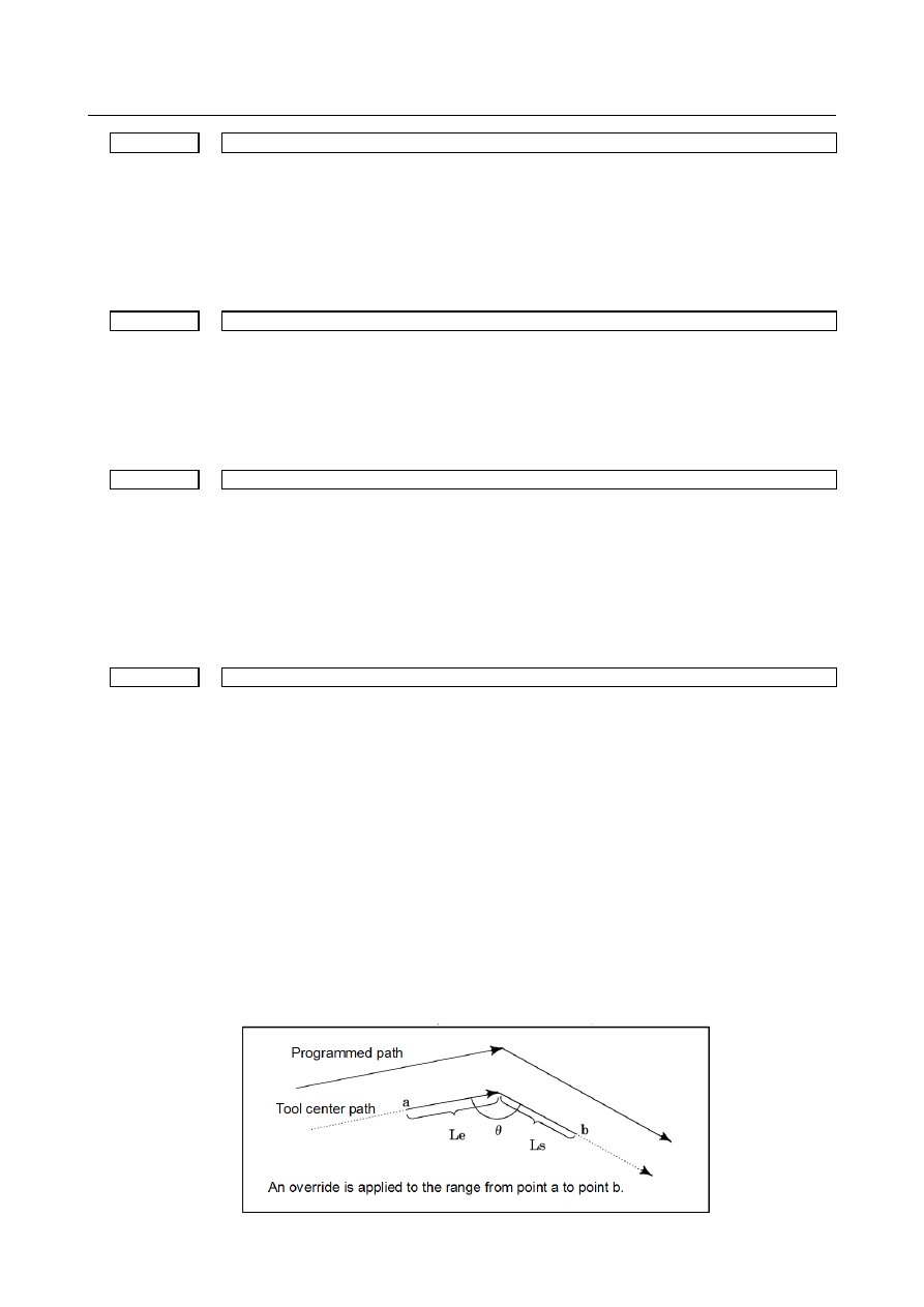
When 

θ


θ

p, an inner corner is assumed. (Parameter No. 1711 is used to set 

θ

p.) 

When a corner is determined to be an inner corner, an override is applied to the feedrate 
in the range of Le in the previous block from the intersection of the corner and in the 
range of Ls in the next block from the intersection of the corner. 
Distances Le and Ls represent linear distances from the intersection of a corner to points 
on the tool center path. 
Le and Ls are set in parameters Nos. 1713 and 1714. 


B-64693EN-1/01


- 1123 - 

7. FEEDRATE CONTROL/ACCELERATION 

AND DECELERATION CONTROL 

7.1.9 

External Deceleration 

Overview 

The control axis is externally decelerated. The feedrate is decelerated by the external deceleration signals 
from the machine. The deceleration rate is set by the parameters. 
The external deceleration signal are provided for each axis and direction. 
As five types of deceleration condition settings can be dynamically selected by the signals. 
External deceleration can be applied to rapid traverse rate, cutting feedrate, and manual handle feedrate. 
For manual handle federate, external deceleration can be applied under the following conditions. 
 

  - 

Rapid traverse and cutting feed 

Five types of deceleration conditions can be set by the parameters. 
When deceleration conditions specified by multiple external signals input during machining are conflicted, 
the condition with the lowest external deceleration rate is applied. 
External deceleration settings 2, 3. 4, and 5 can be switched between enabled and disabled by the 
parameters. 
 

  - 

Manual handle feed 

Five types of deceleration conditions can be set  by the parameters. For handle feed, the maximum 
feedrate is switched when the external deceleration signal in the positive or negative direction for the 
handle axis is set to 0. When multiple conditions are conflicted, the condition with the lowest maximum 
feedrate is applied. 
 

Setting the parameters 

Valid / invalid of the external deceleration signals in the cutting feed and the external deceleration rate 
for linear interpolation type positioning is set by the following parameters. 

No.1005#4 

In cutting feed, an external deceleration signal in the + direction for each axis is disable(0) 
/ enable(1) 

No.1005#5 

In cutting feed, an external deceleration signal in the - direction for each axis is disable(0) 
/ enable(1) 

No.1405#5 

As the external deceleration rate for linear interpolation type positioning, the external 
deceleration rate for cutting feed is used(0) / the external deceleration rate in rapid traverse 
for the 1st axis in the entire system is used(1) 

External deceleration settings 1

5 are set by the following parameters. 


External deceleration 

Meaning 

Setting 1 

Setting 2 

Setting 3 

Setting 4 

Setting 5 

Valid / invalid of the external deceleration 
setting 

No.1406#0 

No.1406#1 

No.12750#0  No.12750#1 

External deceleration rate of cutting feed 

No.1426 

No.1440 

No.1443 

No.12751 

No.12754 

External deceleration rate of rapid traverse 
for each axis 

No.1427 

No.1441 

No.1444 

No.12752 

No.12755 

Maximum manual handle feedrate for each 
axis 

No.1434 

No.1442 

No.1445 

No.12753 

No.12756 


Manual continuous feed 

When  the manual handle feed is enabled (bit 0 (HPG) of parameter No.8131) is 1), and the parameter 
No.7100#0 is set to 1, the external deceleration is enabled as same condition for the manual handle feed. 
Besides, the external deceleration is enabled as same condition for the rapid feed. 


B-64693EN-1/01


- 1124 - 

7. FEEDRATE CONTROL/ACCELERATION AND 

DECELERATION CONTROL 

Signal 

External deceleration signals 1   

*+ED1 to *+ED8<Gn118>,*-ED1 to *-ED8<Gn120> 

External deceleration signals 2   

*+ED21 to *+ED28<Gn101>,*-ED21 to *-ED28<Gn103> 

External deceleration signals 3   

*+ED31 to *+ED38<Gn107>,*-ED31 to *-ED38<Gn109> 

External deceleration signals 4   

*+ED41 to *+ED48<Gn341>,*-ED41 to *-ED48<Gn342> 

External deceleration signals 5   

*+ED51 to *+ED58<Gn343>,*-ED51 to *-ED58<Gn344> 

  [Classification]  Input signal 
 

[Function]  These signals specifies whether to apply external deceleration to each direction for each 

control axis. The sign + or -  preceding ED indicates the direction of feed which is 
decelerated. The number following ED indicates the number of external deceleration 
setting. The last number indicates the number of a control axis. 
* xEDyz 
z :  1 ….. The 1st axis is decelerated. 
 

2 ….. The 2nd axis is decelerated. 


3 ….. The 3rd axis is decelerated. 

           : 
 
y :  None.. External deceleration setting 1 is selected. 
 

2 ….. External deceleration setting 2 is selected. 


3 ….. External deceleration setting 3 is selected. 


4 ….. External deceleration setting 4 is selected. 


5 ….. External deceleration setting 5 is selected. 


x :  + : The feed is decelerated in the plus (+) direction. 
 

- : The feed is decelerated in the minus (-) direction. 


[Operation]  When a signal becomes 0, the corresponding axis decelerates in the specified direction. 


If a specified feedrate is lower than the external deceleration rate, the specified feedrate is 
selected. 


Manual handle feed maximum feedrate change signal HNDLF<Gn023.3> 

  [Classification]  Input signal 
 

[Function]  This signal switches for the maximum handle feedrate. 


[Operation]  When this signal is 0, clamping is performed by the manual rapid traverse rate (parameter 

No. 1424) or parameter No. 1420. The external deceleration function is disabled for 
handle feed. 


  When this signal is 1, clamping is performed by the maximum handle feedrate (parameter 

No. 1434). The external deceleration function is enabled for handle feed. 


Signal address 


#7 

#6 

#5 

#4 

#3 

#2 

#1 

#0 

Gn118 


*+ED8 

*+ED7 

*+ED6 

*+ED5 

*+ED4 

*+ED3 

*+ED2 

*+ED1 


Gn120 


*-ED8 

*-ED7 

*-ED6 

*-ED5 

*-ED4 

*-ED3 

*-ED2 

*-ED1 


Gn101 


*+ED28 

*+ED27 

*+ED26 

*+ED25 

*+ED24 

*+ED23 

*+ED22 

*+ED21 


B-64693EN-1/01


- 1125 - 

7. FEEDRATE CONTROL/ACCELERATION 

AND DECELERATION CONTROL 

Gn103 


*-ED28 

*-ED27 

*-ED26 

*-ED25 

*-ED24 

*-ED23 

*-ED22 

*-ED21 


Gn107 


*+ED38 

*+ED37 

*+ED36 

*+ED35 

*+ED34 

*+ED33 

*+ED32 

*+ED31 


Gn109 


*-ED38 

*-ED37 

*-ED36 

*-ED35 

*-ED34 

*-ED33 

*-ED32 

*-ED31 


Gn341 


*+ED48 

*+ED47 

*+ED46 

*+ED45 

*+ED44 

*+ED43 

*+ED42 

*+ED41 


Gn342 


*-ED48 

*-ED47 

*-ED46 

*-ED45 

*-ED44 

*-ED43 

*-ED42 

*-ED41 


Gn343 


*+ED58 

*+ED57 

*+ED56 

*+ED55 

*+ED54 

*+ED53 

*+ED52 

*+ED51 


Gn344 


*-ED58 

*-ED57 

*-ED56 

*-ED55 

*-ED54 

*-ED53 

*-ED52 

*-ED51 


Gn023 


HNDLF 


Parameter 


#7 

#6 

#5 

#4 

#3 

#2 

#1 

#0 

1005 


EDMx 

EDPx 


[Input type]  Parameter input 


[Data type]  Bit axis 


#4  EDPx

  In cutting feed, an external deceleration signal in the + direction for each axis is: 

0: 

Invalid 

1: 

Valid 


#5  EDMx

  In cutting feed, an external deceleration signal in the - direction for each axis is: 

0: 

Invalid 

1: 

Valid 


#7 

#6 

#5 

#4 

#3 

#2 

#1 

#0 

1405 


EDR 


[Input type]  Parameter input 


[Data type]  Bit path 


#5  EDR

  As the external deceleration rate for linear interpolation type positioning: 

0: 

The external deceleration rate for cutting feed is used. 

1: 

The external deceleration rate in rapid traverse for the 1st axis in the entire system is 
used. 

[Example of external deceleration 1] 
When this parameter is set to 0, the value of parameter No. 1426 is used as the external 
deceleration rate for external deceleration 1. 
When this parameter is set to 1, the parameter No. 1427 for the 1st axis in the entire 
system is used as the external deceleration rate for external deceleration 1. 


#7 

#6 

#5 

#4 

#3 

#2 

#1 

#0 

1406 


EX3 

EX2 


[Input type]  Parameter input 


[Data type]  Bit path 


B-64693EN-1/01


- 1126 - 

7. FEEDRATE CONTROL/ACCELERATION AND 

DECELERATION CONTROL 


#0  EX2

  External deceleration function setting 2 is: 

0: 

Invalid 

1: 

Valid 


#1  EX3

  External deceleration function setting 3 is: 

0: 

Invalid 

1: 

Valid 


1426 


External deceleration rate of cutting feed 


[Input type]  Parameter input 


[Data type]  Real path 


[Unit of data]  mm/min, inch/min, deg/min (machine unit) 

[Min. unit of data]  Depend on the increment system of the reference axis 
[Valid data range]  Refer to the standard parameter setting table (C) 

(When the increment system is IS-B, 0.0 to +999000.0) 
Set an external deceleration rate for cutting feed or positioning of linear interpolation type 
(G00). 
 

1427 


External deceleration rate of rapid traverse for each axis 


[Input type]  Parameter input 


[Data type]  Real axis 


[Unit of data]  mm/min, inch/min, deg/min (machine unit) 

[Min. unit of data]  Depend on the increment system of the applied axis 
[Valid data range]  Refer to the standard parameter setting table (C) 

(When the increment system is IS-B, 0.0 to +999000.0) 
Set the external deceleration rate of rapid traverse for each axis.   
 

1434 


Maximum manual handle feedrate for each axis 


[Input type]  Parameter input 


[Data type]  Real axis 


[Unit of data]  mm/min, inch/min, deg/min (machine unit) 

[Min. unit of data]  Depend on the increment system of the applied axis 
[Valid data range]  Refer to the standard parameter setting table (C) 

(When the increment system is IS-B, 0.0 to +999000.0) 
Set a maximum manual handle feedrate for each axis in case of  manual handle feedrate 
switch signal HNDLF<Gn023.3>=1. 
 

1440 


External deceleration rate setting 2 in cutting feed 


[Input type]  Parameter input 


[Data type]  Real path 


[Unit of data]  mm/min, inch/min, deg/min (machine unit) 

[Min. unit of data]  Depend on the increment system of the reference axis 
[Valid data range]  Refer to the standard parameter setting table (C) 

(When the increment system is IS-B, 0.0 to +999000.0) 
Set external deceleration rate 2 for cutting feed or positioning of linear interpolation type 
(G00). 
 

1441 


External deceleration rate setting 2 for each axis in rapid traverse 


[Input type]  Parameter input 


[Data type]  Real axis 

B-64693EN-1/01


- 1127 - 

7. FEEDRATE CONTROL/ACCELERATION 

AND DECELERATION CONTROL 


[Unit of data]  mm/min, inch/min, deg/min (machine unit) 

[Min. unit of data]  Depend on the increment system of the applied axis 
[Valid data range]  Refer to the standard parameter setting table (C) 

(When the increment system is IS-B, 0.0 to +999000.0) 
Set external deceleration rate 2 for each axis in rapid traverse. 
 

1442 


Maximum manual handle feedrate setting 2 for each axis 


[Input type]  Parameter input 


[Data type]  Real axis 


[Unit of data]  mm/min, inch/min, deg/min (machine unit) 

[Min. unit of data]  Depend on the increment system of the applied axis 
[Valid data range]  Refer to the standard parameter setting table (C) 

(When the increment system is IS-B, 0.0 to +999000.0) 
Set a maximum manual handle feedrate 2 for each axis. 
 

1443 


External deceleration rate setting 3 in cutting feed 


[Input type]  Parameter input 


[Data type]  Real path 


[Unit of data]  mm/min, inch/min, deg/min (machine unit) 

[Min. unit of data]  Depend on the increment system of the reference axis 
[Valid data range]  Refer to the standard parameter setting table (C) 

(When the increment system is IS-B, 0.0 to +999000.0) 
Set external deceleration rate 3 for cutting feed or positioning of linear interpolation type 
(G00). 
 

1444 


External deceleration rate setting 3 for each axis in rapid traverse 


[Input type]  Parameter input 


[Data type]  Real axis 


[Unit of data]  mm/min, inch/min, deg/min (machine unit) 

[Min. unit of data]  Depend on the increment system of the applied axis 
[Valid data range]  Refer to the standard parameter setting table (C) 

(When the increment system is IS-B, 0.0 to +999000.0) 
Set external deceleration rate 3 for each axis in rapid traverse. 
 

1445 


Maximum manual handle feedrate setting 3 for each axis 


[Input type]  Parameter input 


[Data type]  Real axis 


[Unit of data]  mm/min, inch/min (machine unit) 

[Min. unit of data]  Depend on the increment system of the applied axis 
[Valid data range]  Refer to the standard parameter setting table (C) 

(When the increment system is IS-B, 0.0 to +999000.0) 
Set a maximum manual handle feedrate 3 for each axis. 


#7 

#6 

#5 

#4 

#3 

#2 

#1 

#0 

12750 


EX5 

EX4 


[Input type]  Parameter input 


[Data type]  Bit path 


B-64693EN-1/01


- 1128 - 

7. FEEDRATE CONTROL/ACCELERATION AND 

DECELERATION CONTROL 


#0  EX4

  External deceleration function setting 4 is: 

0: 

Disabled. 

1: 

Enabled. 


#1  EX5

  External deceleration function setting 5 is: 

0: 

Disabled. 

1: 

Enabled. 


12751 


External deceleration rate setting 4 in cutting feed 


[Input type]  Parameter input 


[Data type]  Real path 


[Unit of data]  mm/min, inch/min, deg/min (machine unit) 

[Min. unit of data]  Depend on the increment system of the reference axis 
[Valid data range]  Refer to the standard parameter setting table (C) 

(When the increment system is IS-B, 0.0 to +999000.0) 
Set external deceleration rate 4 for cutting feed or positioning of linear interpolation type 
(G00). 
 

12752 


External deceleration rate setting 4 for each axis in rapid traverse 


[Input type]  Parameter input 


[Data type]  Real axis 


[Unit of data]  mm/min, inch/min, deg/min (machine unit) 

[Min. unit of data]  Depend on the increment system of the applied axis 
[Valid data range]  Refer to the standard parameter setting table (C) 

(When the increment system is IS-B, 0.0 to +999000.0) 
Set external deceleration rate 4 for each axis in rapid traverse. 
 

12753 


Maximum manual handle feedrate setting 4 for each axis 


[Input type]  Parameter input 


[Data type]  Real axis 


[Unit of data]  mm/min, inch/min, deg/min (machine unit) 

[Min. unit of data]  Depend on the increment system of the applied axis 
[Valid data range]  Refer to the standard parameter setting table (C) 

(When the increment system is IS-B, 0.0 to +999000.0) 
Set a maximum manual handle feedrate 4 for each axis. 
 

12754 


External deceleration rate setting 5 in cutting feed 


[Input type]  Parameter input 


[Data type]  Real path 


[Unit of data]  mm/min, inch/min, deg/min (machine unit) 

[Min. unit of data]  Depend on the increment system of the reference axis 
[Valid data range]  Refer to the standard parameter setting table (C) 

(When the increment system is IS-B, 0.0 to +999000.0) 
Set external deceleration rate 5 for cutting feed or positioning of linear interpolation type 
(G00). 
 

12755 


External deceleration rate setting 5 for each axis in rapid traverse 


[Input type]  Parameter input 


[Data type]  Real axis 


[Unit of data]  mm/min, inch/min, deg/min (machine unit) 

B-64693EN-1/01


- 1129 - 

7. FEEDRATE CONTROL/ACCELERATION 

AND DECELERATION CONTROL 

[Min. unit of data]  Depend on the increment system of the applied axis 
[Valid data range]  Refer to the standard parameter setting table (C) 

(When the increment system is IS-B, 0.0 to +999000.0) 
Set external deceleration rate 5 for each axis in rapid traverse. 
 

12756 


Maximum manual handle feedrate setting 5 for each axis 


[Input type]  Parameter input 


[Data type]  Real axis 


[Unit of data]  mm/min, inch/min, deg/min (machine unit) 

[Min. unit of data]  Depend on the increment system of the applied axis 
[Valid data range]  Refer to the standard parameter setting table (C) 

(When the increment system is IS-B, 0.0 to +999000.0) 
Set a maximum manual handle feedrate 5 for each axis. 
 

7.1.9.1 

Deceleration area setting 

When the axis is moved to outside specified area, the feedrate can be automatically decelerated. 
In area that the movement condition is severe (the end point of stroke ,etc), the feedrate can be decreased. 
Therefore, the feedrate ban be increased in other areas. 
This function is activated when bit 0 (ADE) of parameter No.12780 is set to 1. 
 

NOTE 

1  For this function, enable "External Deceleration"(bit 2(EDC) of parameter 

No.8131 is 1). 

2  This function is also invalid for functions in which external deceleration is invalid. 


Explanation 

Set to the deceleration area by the parameter No.12781 and No.12782. 
If the axis is outside this area, the feedrate is automatically reduced so that the feedrate after applying the 
override is less than the speed set by parameter No. 12783(rapid traverse) or No.12784(cutting feed). 


Parameter 

Rapid traverse 

Cutting feed 

Deceleration rate 

12783 

12784 


3-dimensional coordinate conversion / Tilted working plane command 

When this function is used in 3-dimensional coordinate conversion / tilted working plane indexing, set the 
linear interpolation positioning (parameter LRP (No.1401#1)=1). 
 

- Use with other functions 

This function is disabled when the following functions are used together. 

- Manual operation 
- PMC control function 
- Real time custom macro 

Deceleration 

area 

Direction of plus 

Parameter 

No.12782 

Parameter 

No.12781 

Deceleration 

area 

Direction of minus 


Content      ..     144      145      146      147     ..