FANUC Series 0i-MODEL F Plus. CONNECTION MANUAL (FUNCTION) - page 135
 

  Index      Manuals     FANUC Series 0i-MODEL F Plus. CONNECTION MANUAL (FUNCTION) B-64693EN-1/01


Search            copyright infringement  


Content      ..     133      134      135      136     ..


FANUC Series 0i-MODEL F Plus. CONNECTION MANUAL (FUNCTION) - page 135


6. INTERPOLATION FUNCTION


B-64693EN-1/01


- 1034 - 

  - 

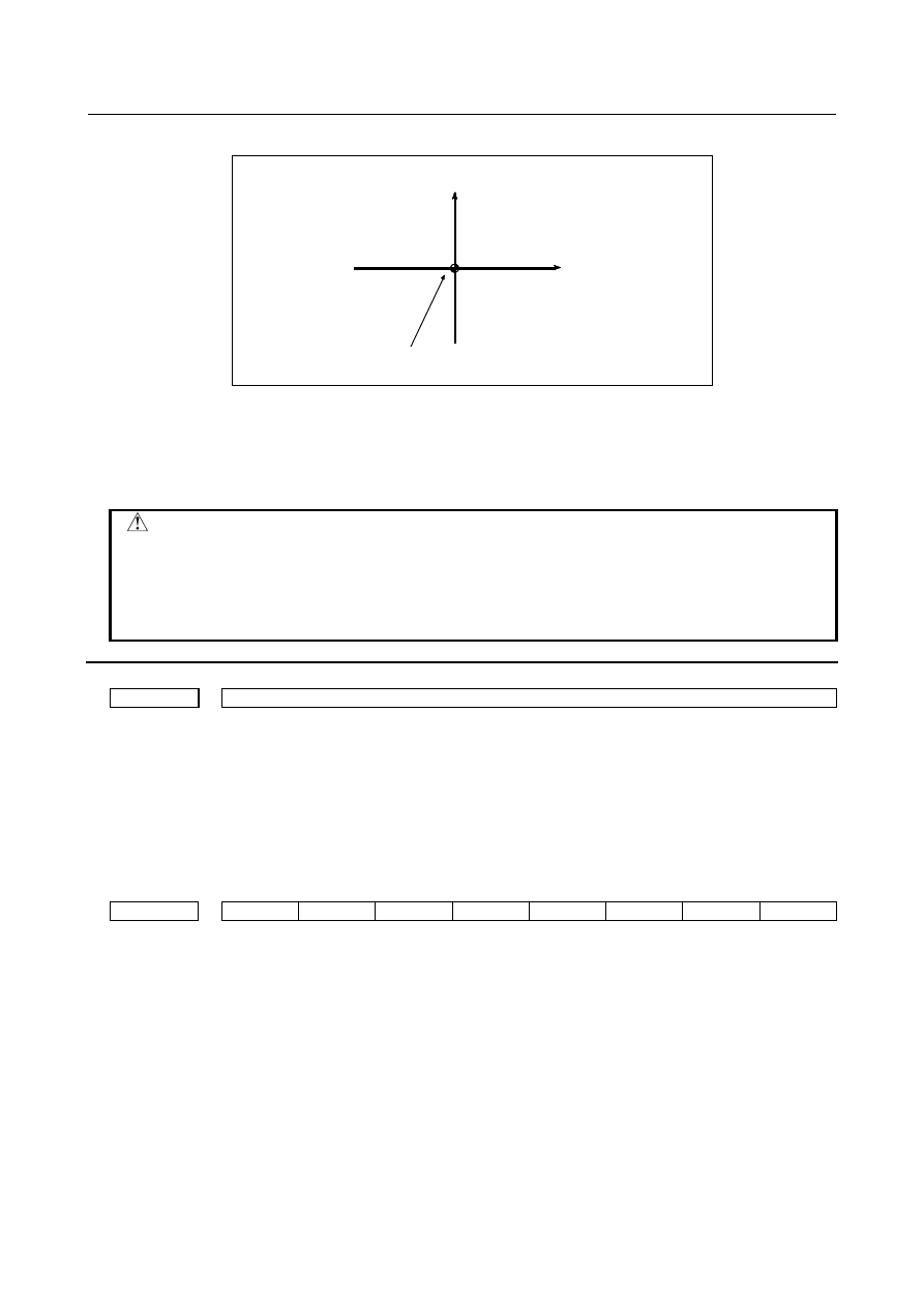
Polar coordinate interpolation plane 


Rotary axis (virtual axis)   

(unit:    mm or inch) 

Linear axis 
(unit:    mm or inch) 

Origin of the local coordinate system (G52 command) 
(Or origin of the workpiece coordinate system when not commanding in G52.) 


Fig. 6.7 (a) Polar coordinate interpolation plane 

 
When the power is turned on or the system is reset, polar coordinate interpolation is canceled (G13.1). 
The linear and rotation axes for polar coordinate interpolation must be set in parameters Nos. 5460 and 
5461 beforehand. 
 

  CAUTION 


The plane used before G12.1 is specified (plane selected by G17, G18, or G19) is 
canceled. It is restored when G13.1 (canceling polar coordinate interpolation) is 
specified. 


When the system is reset, polar coordinate interpolation is canceled and the 
plane specified by G17, G18, or G19 is used. 


Parameter 

1430 


Maximum cutting feedrate for each axis 


[Input type]  Parameter input 


[Data type]  Real axis 


[Unit of data]  mm/min, inch/min, deg/min (machine unit) 

[Min. unit of data]  Depend on the increment system of the applied axis 
[Valid data range]  Refer to the standard parameter setting table (C) 

(When the increment system is IS-B, 0.0 to +999000.0) 
Specify the maximum cutting feedrate for each axis. 


#7 

#6 

#5 

#4 

#3 

#2 

#1 

#0 

5450 


PRD 

PIC 


PLS 


PDI 


[Input type]  Parameter input 


[Data type]  Bit path 


#0  PDI

  When the second axis on the plane in the polar coordinate interpolation mode is based on 

radius specification: 
0: 

Radius specification is used. 

1: 

Diameter specification is used. 


#2  PLS

  The polar coordinate interpolation shift function is: 

0: 

Not used. 

1: 

Used. 

This enables machining using the workpiece coordinate system with a desired point 
which  is not the center of the rotation axis set as the origin of the coordinate system in 
polar coordinate interpolation. 

B-64693EN-1/01


6. INTERPOLATION FUNCTION


- 1035 - 


#5


PIC

  The initial display type of the absolute position of the linear and rotary axes to be used in 

the polar coordinate interpolation is: 
0: 

Actual position. 

1: 

Cartesian coordinates in the polar coordinate interpolation plane. 


NOTE 

1  The display type can be switched via the soft key [CARTES ON] / 

[CARTES OFF] in the absolute position display screen. 

2  This parameter does not change if switching the display type via the 

soft key. 


#6


PRD

  When the first axis on the plane in the polar coordinate interpolation mode is based on 

diameter specification: 
0: 

Diameter specification is used. 

1: 

Radius specification is used. 


5460 


Axis (linear axis) specification for polar coordinate interpolation 


[Input type]  Parameter input 


[Data type]  Byte path 

[Valid data range]  1 to number of controlled axes 

This parameter sets control axis numbers of linear axis to execute polar interpolation. 
 

5461 


Axis (rotation axis) specification for polar coordinate interpolation 


[Input type]  Parameter input 


[Data type]  Byte path 

[Valid data range]  1 to number of controlled axes 

This parameter sets control axis numbers of rotation axis to execute polar interpolation. 
 

5463 


Automatic override tolerance ratio for polar coordinate interpolation 


[Input type]  Parameter input 


[Data type]  Byte path 


[Unit of data]  % 

[Valid data range]  0 to 100 

Typical setting: 90% (treated as 90% when set to 0) 
Set the tolerance ratio of the fastest cutting feedrate to the speed of the rotation axis 
during automatic override of polar coordinate interpolation. 
 

5464 


Compensation for error on hypothetical axis of polar coordinate interpolation 


[Input type]  Parameter input 


[Data type]  Byte path 


[Unit of data]  mm, inch (input unit) 

[Min. unit of data]  Depend on the increment system of the reference axis 
[Valid data range]  9 digit of minimum unit of data (refer to standard parameter setting table (A)) 

(For IS-B, -999999.999 to +999999.999) 
This parameter is used to set the error if the center of the rotation axis on which polar 
coordinate interpolation is performed is not on the X-axis. 
If the setting of the parameter is 0, regular polar coordinate interpolation is performed. 
 

6. INTERPOLATION FUNCTION


B-64693EN-1/01


- 1036 - 

Alarm and message 

Number 

Message 

Description 

PS0145 

ILLEGAL USE OF 
G12.1/G13.1 

The axis No. of plane selection parameter No. 5460 (linear axis) and No. 
5461(axis of rotation) in the polar coordinate interpolation mode is out of 
range (1 to number of controlled axes). 

PS0146 

ILLEGAL USE OF G-CODE  The modal G code group contains an illegal G code in the polar 

coordinate interpolation mode or when a mode was canceled. 
Only the following G codes are allowed: G40, G50, G69.1 
An illegal G code was specified while in the polar coordinate 
interpolation mode. 
The following C codes are not allowed: G27, G28, G30, G31 to G31.4, 
G37 to G37.3, G52, G92, G53, G17 to G19, G81 to G89, G68 
In the 01 group, G codes other than G01, G02 and G03 cannot be 
specified. 

DS1512 

EXCESS VELOCITY 

The feedrate of the linear axis during polar coordinate interpolation 
exceeded the maximum cutting feedrate. 

DS1514 

ILLEGAL MOTION IN 
G12.1 MODE 

In a hypothetical axis direction compensation during the polar coordinate 
interpolation mode, an attempt is made to travel to the area in which the 
travel cannot be made. 


Reference item 

Manual name 

Item name 

OPERATOR’S MANUAL (B-64694EN) 

Polar coordinate interpolation 


6.8 

CYLINDRICAL INTERPOLATION 

6.8.1 

Cylindrical Interpolation 

Overview 

The cylindrical interpolation function performs linear interpolation or arc interpolation with another axis 
by converting the travel distance of a rotation axis specified in degrees to the travel distance on the 
circumference. 
Since programming is  allowed with the side of a cylinder developed, a program for cylinder cam 
grooving or other machining can easily be created. 
 

Explanation 

  - 

Plane selection (G17, G18, G19) 

To specify a G code for plane selection, set the rotary axis in parameter No. 1022 as a linear axis that is 
one of the basic three axes of the basic coordinate system or an axis parallel to one of the basic axes. For 
example, when rotary axis C-axis is assumed to be parallel to the X-axis, specifying G17, axis address C, 
and Y at the same time can select a plane formed by the C-axis and Y-axis (the Xp-Yp plane). 
Only an axis can be set to the rotary axis of cylindrical interpolation. 
 

6.8.2 

Cylindrical Interpolation by Plane Distance Command 

Overview 

In the conventional rotary axis command in cylindrical interpolation, the angle of the rotary axis is 
specified.   
This function enables the rotary axis command in cylindrical interpolation to be specified by distance on 
the developed plane by setting bit 2(DTO) of parameter No.3454.   
 

B-64693EN-1/01


6. INTERPOLATION FUNCTION


- 1037 - 

NOTE 

1. 

Do not change the parameter DTO while cylindrical interpolation mode. 

2. 

To use the function, enable "cylindrical interpolation" (bit 6 (NCL) of 

parameter No.8137#6 is 0). 


6.8.3 

Cylindrical Interpolation Cutting Point Compensation 

Overview 

The conventional cylindrical interpolation function controls the movement of the tool center so that the 
tool axis moves along a specified path on the cylindrical surface to always face toward the rotation axis of 
the workpiece (cylindrical axis). 
On the other hand, the cylindrical interpolation cutting point control function controls the tool so that the 
tangent from the tool to the cutting face of a contour figure passes the rotation center of the workpiece at 
all times. 
That is, the cutting face of a contour figure is always perpendicular to the cylinder. Therefore, the figure 
of the cutting face can be kept identical regardless of the cutter compensation. 
 

NOTE 

To use the function, enable "cylindrical interpolation" (bit 6 (NCL) of parameter 
No.8137#6 is 0). 


Parameter 

  - 

Settings common to cylindrical interpolation, cylindrical interpolation by plane 
distance command, and cylindrical interpolation cutting point compensation 


#7 

#6 

#5 

#4 

#3 

#2 

#1 

#0 

1006 


ROSx 

ROTx 


[Input type]  Parameter input 


[Data type]  Bit axis 


NOTE 


When at least one of these parameters is set, the power must be 
turned off before operation is continued. 


#0  ROTx


#1  ROSx 

Setting linear or rotary axis. 

ROSx 

ROTx 

Meaning 

Linear axis 
(1)  Inch/metric conversion is done. 
(2)  All coordinate values are linear axis type. (Is not rounded in 0 to 360

°

(3)  Stored pitch error compensation is linear axis type (Refer to parameter No. 

3624) 

Rotary axis (A type) 
(1)  Inch/metric conversion is not done. 
(2)  Machine coordinate values are rounded in 0 to 360

°

. Absolute coordinate 

values are rounded or not rounded by bits 0 (ROAx) and 2 (RRLx) of 
parameter No. 1008. 

(3)  Stored pitch error compensation is the rotation type. (Refer to parameter No. 

3624) 

(4)  Automatic reference position return (G28, G30) is done in the reference 

position return direction and the move amount does not exceed one rotation. 

6. INTERPOLATION FUNCTION


B-64693EN-1/01


- 1038 - 

ROSx 

ROTx 

Meaning 

Rotary axis (B type) 
(1)  Inch/metric conversion is not done. 
(2)  Machine coordinate values, absolute coordinate values and relative 

coordinate values are linear axis type. (Is not rounded in 0 to 360

°

). 

(3)  Stored pitch error compensation is linear axis type (Refer to parameter No. 

3624) 

(4)  Cannot be used with the rotary axis roll-over function and the index table 

indexing function (M series) 

Except for the 

above. 

Setting is invalid (unused) 


1022 


Setting of each axis in the basic coordinate system 


[Input type]  Parameter input 


[Data type]  Byte axis 

[Valid data range]  0 to 7 

To determine a plane for circular interpolation, cutter compensation, and so forth (G17: 
Xp-Yp plane, G18: Zp-Xp plane, G19: Yp-Zp plane) and a 3-dimensional tool 
compensation space (XpYpZp), specify which of the basic three axes (X, Y, and Z) is 
used for each control axis, or a parallel axis of which basic axis is used for each control 
axis. 
A basic axis (X, Y, or Z) can be specified only for one control axis. 
Two or more control axes can be set as parallel axes for the same basic axis. 

Setting 

Meaning 

Rotary axis (Neither the basic three axes nor a parallel axis ) 

X axis of the basic three axes 

Y axis of the basic three axes 

Z axis of the basic three axes 

Axis parallel to the X axis 

Axis parallel to the Y axis 

Axis parallel to the Z axis 

 
In general, the increment system and diameter/radius specification of an axis set as a 
parallel axis are to be set in the same way as for the basic three axes. 
 

1260 


The shift amount per one rotation of a rotary axis 


NOTE 


When this parameter is set, the power must be turned off before 
operation is continued. 


[Input type]  Parameter input 


[Data type]  Real axis 


[Unit of data]  deg 

[Min. unit of data]  Depend on the increment system of the applied axis 
[Valid data range]  0 or positive 9 digit of minimum unit of data (refer to the standard parameter setting table 

(B)) 
(When the increment system is IS-B, 0.0 to +999999.999) 
Set the shift amount per one rotation of a rotary axis. 
For the rotary axis used for cylindrical interpolation, set the standard value. 
 

B-64693EN-1/01


6. INTERPOLATION FUNCTION


- 1039 - 

  - 

Parameters required for cylindrical interpolation by plane distance command 


#7 

#6 

#5 

#4 

#3 

#2 

#1 

#0 

3454 


DTO 


[Input type]  Parameter input 


[Data type]  Bit path 


#2  DTO 

The method of specifying a rotation axis in cylindrical interpolation mode is set. 
0: 

In cylindrical interpolation mode, the rotation axis is specified by angle. 

1: 

In cylindrical interpolation mode, the rotation axis is specified by distance on an 
expanded plane. 


  - 

Parameters required for cylindrical interpolation cutting point compensation 


#7 

#6 

#5 

#4 

#3 

#2 

#1 

#0 

19530 


CYS 

CYA 


[Input type]  Parameter input 


[Data type]  Bit path 


#5  CYA

  Specifies whether to perform cylindrical interpolation cutting point compensation in the 

cylindrical interpolation command (G07.1). 
0: 

Perform. 

1: 

Do not perform. 


#6  CYS

  Specifies whether when the cylindrical interpolation cutting point compensation function 

is used, cutting point compensation is performed between blocks or together with a block 
movement if the cutting point compensation value is less than the setting of parameter No. 
19534. 
0: 

Performed between blocks. 

1: 

Performed together with a block movement if the cutting point compensation value 
is less than the setting of parameter No. 19534. 


19531 


Tool offset axis number for the XY plane 


19532 


Tool offset axis number for the ZX plane 


19533 


Tool offset axis number for the YZ plane 


[Input type]  Parameter input 


[Data type]  Byte path 

[Valid data range]  1 to number of controlled axes 

Specify a tool offset axis that intersects the cylindrical rotation axis at right angles. 
 

19534 


Limit for changing cylindrical interpolation cutting point compensation in a single block 


[Input type]  Parameter input 


[Data type]  Real path 


[Unit of data]  mm, inch (input unit) 

[Min. unit of data]  Depend on the increment system of the reference axis 
[Valid data range]  1 to 999999999 

The following operation is performed, depending on the setting of parameter No. 19530: 
(1)  Bit 6 (CYS) of parameter No. 19530) is set to 0 

6. INTERPOLATION FUNCTION


B-64693EN-1/01


- 1040 - 


If the amount of cylindrical interpolation cutting point compensation is smaller than 
the value set in this parameter, cylindrical interpolation cutting point compensation 
is not performed. Instead, this ignored amount of cylindrical interpolation cutting 
point compensation is added to the next amount of cylindrical interpolation cutting 
point compensation to determine whether to perform cylindrical interpolation cutting 
point compensation. 

 
(2)  Bit 6 (CYS) of parameter No. 19530) is set to 1 
 

If the amount of cylindrical interpolation cutting point compensation is smaller than 
the value set in this parameter, cylindrical interpolation cutting point compensation 
is performed together with the movement of the specified block. 


NOTE 


Set this parameter as follows: 


Setting < (setting for a rotation axis in parameter No. 1430) 

×

 4/3 

where 4/3 is a constant for internal processing. 


19535 


Limit of travel distance moved with the cylindrical interpolation cutting point compensation in the 

previous block unchanged. 


[Input type]  Parameter input 


[Data type]  Real path 


[Unit of data]  mm, inch (input unit) 

[Min. unit of data]  Depend on the increment system of the reference axis 
[Valid data range]  1 to 999999999 

The following operation is performed, depending on the type of interpolation: 
(1)  For linear interpolation 
 

If the travel distance in a specified block is smaller than the value set in this 
parameter, machining is performed without changing the cylindrical interpolation 
cutting point compensation in the previous block. 

(2)  For circular interpolation 
 

If the diameter of a specified arc is smaller than the value set in this parameter, 
machining is performed without changing the cylindrical interpolation cutting point 
compensation in the previous block. Cylindrical interpolation cutting point 
compensation is not performed according to a circular movement. 


Alarm and message 

Number 

Message 

Description 

PS0015 

TOO MANY 
SIMULTANEOUS AXES 

A move command was specified for more axes than can be controlled 
by simultaneous axis control. 
Divide the number of programmed move axes into two blocks. 

PS0175 

ILLEGAL G07.1 AXIS 

An axis which cannot perform cylindrical interpolation was specified. 
More than one axis was specified in a G07.1 block. An attempt was 
made to cancel cylindrical interpolation for an axis that was not in the 
cylindrical interpolation mode. 
For the cylindrical interpolation axis, set not 0 but one of 5, 6 or 7 
(parallel axis specification) to parameter No. 1022 to instruct the arc 
with axis of rotation (bit 0 (ROT) of parameter No. 1006 is set to 1 and 
parameter No. 1260 is set) ON. 

PS0176 

ILLEGAL G-CODE 
USE(G07.1 MODE) 

A G code was specified that cannot be specified in the cylindrical 
interpolation mode. This alarm also is generated when an 01 group G 
code was in the G00 mode or code G00 was instructed. 
Cancel the cylindrical interpolation mode before instructing code G00. 


B-64693EN-1/01


6. INTERPOLATION FUNCTION


- 1041 - 

Reference item 

Manual name 

Item name 

OPERATOR’S MANUAL (B-64694EN) 

Cylindrical interpolation 


6.9 

POLYGON TURNING 

T


Polygon turning means machining a workpiece to a polygonal figure by rotating the workpiece and tool at 
a certain ratio. 


Workpiece 

Workpiece 

Tool 


Fig. 6.9 (a)   

 
By changing conditions which are rotation ratio of workpiece and tool and number of cutters, the 
workpiece can be machined to a square or hexagon. The machining time can be reduced as compared 
with polygonal figure machining using the polar coordinate interpolation.   
The machined figure, however, is not exactly polygonal. Generally, polygon turning is used for the heads 
of square and/or hexagon bolts or hexagon nuts. 
As the tool rotary axis, one of the following can be used: 
  - 

CNC controlled axis (servo axis) 

  - 

Second spindle (Two serial spindles are connected.) 

Polygon turning performed using a servo axis as the tool rotary axis is referred to as polygon turning. 
Polygon turning performed using the second spindle as the tool rotary axis is referred to as polygon 
turning with two spindles. 
 

Table 6.9 (a) 

Function name


Workpiece axis


Tool rotary axis


Polygon turning 

Spindle 
(Either an analog spindle or serial spindle is usable. However, 
a detector equivalent to a position coder is required.) 

Servo axis 

Polygon turning with two 
spindles 

Spindle 
(Serial spindle) 

Spindle 
(Serial spindle) 

 
The specifications of polygon turning are described below. 
For details of polygon turning with two spindles, see the specifications of polygon turning with two 
spindles. 
 

6.9.1 

Polygon Turning 

Overview 

A CNC controlled axis (servo axis) is assigned to the tool rotary axis.   
This rotary axis of tool is called Y-axis in the following description. As the workpiece axis (spindle), 
either a serial spindle or analog spindle can be used. 
The Y-axis is controlled by the G51.2 command, so that the ratio of the rotation speeds of the spindle 
(previously specified by S-command) and the tool becomes the specified ratio. 
When simultaneous start is specified by G51.2, the one-rotation signal sent from the position codes set on 
the spindle is detected. After one-rotation signal detection, the Y-axis is controlled using the rotation ratio 


Content      ..     133      134      135      136     ..