FANUC Series 0i-MODEL F Plus. CONNECTION MANUAL (FUNCTION) - page 108
 

  Index      Manuals     FANUC Series 0i-MODEL F Plus. CONNECTION MANUAL (FUNCTION) B-64693EN-1/01


Search            copyright infringement  


Content      ..     106      107      108      109     ..


FANUC Series 0i-MODEL F Plus. CONNECTION MANUAL (FUNCTION) - page 108


5. AUTOMATIC OPERATION


B-64693EN-1/01


- 818 - 


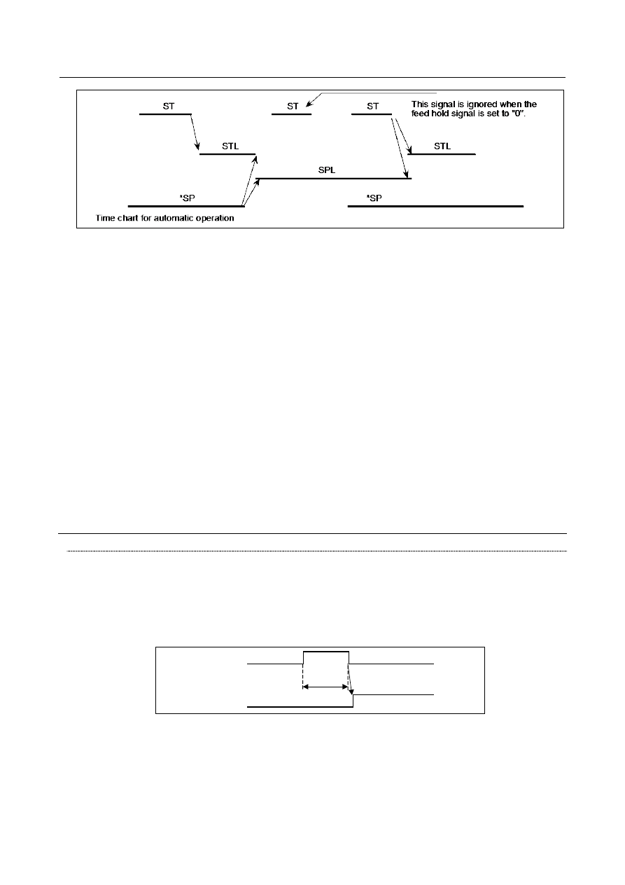
Fig. 5.1 (a) 

 
When signal *SP is set to 0 during the execution of a block containing only the M, S, T, or B function, 
signal STL is immediately set to 0, signal SPL is set to 1, and the CNC enters the feed hold state. If the 
FIN signal is subsequently sent from the PMC, the CNC executes processing up until the end of the block 
that has been halted. Upon the completion of that block, signal SPL is set to 0 (signal STL remains set to 
0) and the CNC enters the automatic operation stop state. 
(a)  During threading 

When signal *SP is set to 0 during threading, the CNC enters the feed hold state after executing a 
non-threading block after the threading blocks. 


In lathe system, when signal *SP is set to 0 during threading with the G92 command (threading 
cycle), signal SPL is immediately set to 1 but operation continues up until the end of the retraction 
block following threading. When signal *SP is set to 0 during threading with the G32 (M series: 
G33) command, signal SPL is immediately set to 1 but operation continues until the end of a 
non-threading block following the threading blocks. (Stopping feeding during threading is dangerous 
because the amount of cutting will increase.) 

(b)  During tapping in a canned cycle 
 

When signal *SP is set to 0 during tapping in a canned cycle (G84), signal SPL is immediately set to 
1 but operation continues until the tool returns to the initial level or R point level after the 
completion of tapping. 

(c)  When a macro instruction is being executed 

Operation stops after the currently executing macro instruction has been completed. 


Signal 

Cycle start signal ST<Gn007.2> 

    [Classification]  Input signal 
 

  [Function]  Starts automatic operation. 


  [Operation]  When signal ST is set to 1 then 0 in memory (MEM) mode, DNC operation mode (RMT) 

or manual data input (MDI) mode, the CNC enters the cycle start state and starts 
operation. 
MEM, RMT, or MDI mode 


. . . . 


Start 


Signal ST  "1" 
 

"0" 


Automatic operation 


32 msec 

or more 


Fig. 5.1 (b) 


B-64693EN-1/01


5. AUTOMATIC OPERATION


- 819 - 

Feed hold signal *SP<Gn008.5> 

  [Classification]  Input signal 
 

[Function]  Halts automatic operation. 


[Operation]  When signal *SP is set to 0 during automatic operation, the CNC enters the feed hold 

state and stops operation. Automatic operation cannot be started when signal *SP is set to 
0. 
MEM, RMT, or MDI mode 


Fig. 5.1 (c) 


Automatic operation signal OP<Fn000.7> 

    [Classification]  Output signal 
   

[Function]  Notifies the PMC that automatic operation is in progress. 

    [Output cond.]  This signal is set to 1 or 0, according to the state of the CNC, as listed in Table 5.1 (a). 


Cycle start lamp signal STL<Fn000.5> 

    [Classification]  Output signal 
 

  [Function]  Notifies the PMC that automatic operation start is entered. 

    [Output cond.]  This signal is set to 1 or 0, according to the state of the CNC, as listed in Table 5.1 (a). 


Feed hold lamp signal SPL<Fn000.4> 

    [Classification]  Output signal 
 

[Function]  Notifies the PMC that feed hold state is entered. 

    [Output cond.]  This signal is set to 1 or 0, according to the state of the CNC, as listed in Table 5.1 (a). 

Signals OP, STL, and SPL are the signals to inform PMC of the operation condition of 
CNC. 

Table 5.1 (a) Status of operation 

Signal name 

State of the operation


Cycle start lamp 

STL


Feed hold lamp 

SPL


Automatic 

operation lamp OP


Cycle start state


Feed hold state


Automatic operation stop state


Reset state


(a)  Cycle start state 

The CNC is executing memory operation or manual data input operation commands. 

(b)  Feed hold state 

The CNC is not executing memory operation nor manual data input operation 
commands while the commands to be executed remain. 

(c)  Automatic operation stop state 

Memory operation or manual data input operation has been completed and stopped. 

(d)  Reset state 

The automatic operation has been forcibly terminated. 


5. AUTOMATIC OPERATION


B-64693EN-1/01


- 820 - 

NOTE 


If bit 2 (OPS) of parameter No. 11223 is set to 1, signal OP is set to 
1 when a sequence number is searched for by operating keys on 
the MDI unit in the automatic operation mode (MEM). 


Signal address 


#7 

#6 

#5 

#4 

#3 

#2 

#1 

#0 

Gn007 


ST 


Gn008 


*SP 


#7 

#6 

#5 

#4 

#3 

#2 

#1 

#0 

Fn000 


OP 


STL 

SPL 


Parameter 


#7 

#6 

#5 

#4 

#3 

#2 

#1 

#0 

11223 


OPS 


[Input type]  Parameter input 


[Data type]  Bit path 


#2  OPS

  In the MEM mode, when a sequence number search operation ([N SEARCH]) is 

performed, automatic operation signal OP <Fn000.7> is: 
0: 

Kept 0. 

1: 

Set to 1. 


Alarm and message 

  - 

Self-diagnosis information 

During automatic operation, the machine may sometimes show no movement while no alarm is detected. 
In that case, the CNC may be performing processing or waiting for the occurrence of an event. The state 
of the CNC can be obtained using the CNC self-diagnosis function (diagnosis data 1000 to 1015). 
 

Reference item 

Manual name 

Item name 

OPERATOR’S MANUAL (B-64694EN) 

Memory operation 
MDI operation 

DNC operation 
Checking by self-diagnosis screen 


5.2 

RESET AND REWIND 

Overview 

The CNC is reset and enters the reset state in the following cases: 
1. 

When the emergency stop signal (*ESP) is set to 0 

2. 

When the external reset signal (ERS) is set to 1 

3. 

When the reset and rewind signal (RRW) is set to 1 

4. 

When MDI 


  key is pressed 

When the CNC is reset, the resetting signal (RST) is output to the PMC. The resetting signal (RST) is set 
to 0 when the resetting signal output time, set with parameter No. 3017, has elapsed after the above 
conditions have been released. 
RST signal output time = Treset (Reset processing time) + (parameter setting value) 

×

 16 msec. 

B-64693EN-1/01


5. AUTOMATIC OPERATION


- 821 - 


Fig. 5.2 (a) 


  CAUTION 


Treset requires at least 16 msec. This time will be longer on optional 
configurations. 

 
When the CNC is reset during automatic operation, automatic operation is stopped and tool movement 
along the controlled axis is decelerated and stopped

(CAUTION  1)

. When the CNC is reset during the 

execution of the M, S, T, or B function, signal MF, SF, TF, or BF is set to 0 within 100 ms. 
Tool movement along the controlled axis is also decelerated and stopped

(CAUTION 1)

  in manual operation 

(jog feed, manual handle feed, incremental feed, or etc). 
 

  CAUTION 


When the emergency stop signal (*ESP) is set to 0, the tool is stopped by an 
emergency stop. 

 
Bit 6 (CLR) of parameter No. 3402 is used to select whether the CNC internal data (such as modal G 
codes) is cleared or reset when the CNC is reset. Refer to the Appendix F, "Status when turning on power, 
when cleared, and when reset" in the Operator's Manual for the state of the internal data when cleared or 
reset. 
The following parameters are also used to select how to handle processing for CNC data when the CNC is 
reset. 


Bit 7 (MCL) of parameter No. 3203 
Whether programs created in MDI mode are erased or stored 


Bit 6 (CCV) of parameter No. 6001 
Whether custom macro variables #100 to #149 (or to #199) are cleared or stored 


Warning indication during a reset in program operation 

On the reset state setting for address G, F, H, D, T, S, M, or B (second auxiliary function) when reset 
occurs,  if a reset occurs during block execution in program operation, modal information returns to the 
state before block execution.  Therefore, the warning "MODAL DATA IS CHANGED BY BLOCK 
STOP" can be displayed so that the operator may notice the modal information is not updated by 
information of the interrupted block.   
To enable or disable the warning, set bit 1 (WMD) of parameter No. 10334. 
However, the warning is not displayed if a reset occurs by the reset of the reset & rewind signal RRW. 
 

  - 

Reset & Rewind 

When the reset & rewind signal RRW becomes 1, a reset and rewinding are performed. 
Rewinding is described below. 
1. 

When automatic operation (DNC operation (RMT)) mode is selected,  if  a portable tape reader is 
connected to the selected input/output equipment, the portable tape reader is rewound. 


The rewinding signal RWD is output while the portable tape reader is being rewound. This signal 
becomes 0 when rewinding is completed. 

2. 

When automatic operation (Memory  operation (MEM)) mode  or Memory edit (EDIT) mode  is 
selected, the beginning of the selected program is found. When automatic operation (Manual data 

5. AUTOMATIC OPERATION


B-64693EN-1/01


- 822 - 

input (MDI)) mode is selected, if reset is performed, motion is different according to the state of the 
program execution and the parameter setting. For details, refer to III-4.2,  “MDI OPERATION”  in 
the OPERATOR’S MANUAL (Common to Lathe System / Machining Center System) 
(B-64694EN).  Bit 2 (RWM) of parameter No. 3001 can be used to specify whether the rewinding 
signal RWD is output. 


When RWM is 1, the rewinding signal RWD is kept 1 for 100 ms and then becomes 0. Since the 
time required for finding the beginning of the program in memory is almost zero, the beginning is 
already found by the time the rewinding signal RWD becomes 0. 


Reset & Rewind in manual mode 

When bit 0 (MRW) of parameter No.10337 is set to 1, the rewind of a program by reset & rewind RRW 
<Gn008.6> has been possible in manual mode. 
 

Signal 

External reset signal ERS<Gn008.7> 

    [Classification]  Input signal 
   

[Function]  Reset the CNC. 


[Operation]  Turning the signal ERS to 1 resets the CNC and enters the reset state. While the CNC is 

reset, the resetting signal RST turns to 1. 


Reset & rewind signal RRW<Gn008.6> 

    [Classification]  Input signal 
   

[Function]  CNC is reset and a program under an automatic operation is rewound. 


  [Operation]  As described in the item "Reset & Rewind". 


Resetting signal RST<Fn001.1> 

    [Classification]  Output signal 
 

[Function]  Notifies the PMC that the CNC is being reset. This signal is used for reset processing on 

the PMC. 

    [Output cond.]  This signal is set to 1 in the following cases: 

1. When the emergency stop signal (*ESP) is set to 0 
2. When the external reset signal (ERS) is set to 1 
3. When the reset & rewind signal (RRW) is set to 1 

4. When MDI 


  key is pressed 

This signal is set to 0 in the following case: 

When the resetting signal output time, set with parameter No. 3017, has elapsed 
after the above conditions have been released and the CNC is reset 


Rewinding signal RWD<Fn000.0> 

  [Classification]  Output signal 
 

[Function]  Notifies the PMC that the CNC is being rewound. 


[Output cond.]  As described in the item "Reset and Rewind". 


MDI reset confirmation signal MDIRST<Fn006.1> 

  [Classification]  Output signal 


[Function]  Notifies the PMC that the MDI 


  key has been pressed. 


[Output cond.]  This signal is set to 1 when: 

The 


  key is pressed when a path for which MDI reset is enabled is selected. 

B-64693EN-1/01


5. AUTOMATIC OPERATION


- 823 - 

This signal is set to 0 when: 

The MDI 


  key is not pressed. 

A path for which MDI reset is not enabled is selected. 


Signal address 


#7 

#6 

#5 

#4 

#3 

#2 

#1 

#0 

Gn008 


ERS 

RRW 


#7 

#6 

#5 

#4 

#3 

#2 

#1 

#0 

Fn000 


RWD 


Fn001 


RST 


Fn006 


MDIRST 


Parameter 


#7 

#6 

#5 

#4 

#3 

#2 

#1 

#0 

3001 


RWM 


[Input type]  Parameter input 


[Data type]  Bit path 


#2  RWM

  While  the beginning of  a program in the program memory is being searched for, the 

rewind signal RWD is: 
0: 

Not output. 

1: 

Output. 


3017 


Output time of reset signal RST 


[Input type]  Parameter input 


[Data type]  Word path 


[Unit of data]  16msec 

[Valid data range]  0 to 255 

When the output time of the reset signal RST is to be extended, set an extended time. 
(RST signal output time) = 
  (Time required for reset processing) + (Parameter setting) 

×

 16 msec 


#7 

#6 

#5 

#4 

#3 

#2 

#1 

#0 

3203 


MCL 


[Input type]  Parameter input 


[Data type]  Bit path 


#7  MCL

  Whether a program prepared in the MDI mode is cleared by reset 

0: 

Not deleted 

1: 

Deleted   


#7 

#6 

#5 

#4 

#3 

#2 

#1 

#0 

3402 


CLR 


[Input type]  Parameter input 


[Data type]  Bit path 


5. AUTOMATIC OPERATION


B-64693EN-1/01


- 824 - 


#6  CLR

  Reset button on the  MDI unit, external reset signal, reset and rewind  signal, and 

emergency stop signal 
0: 

Cause reset state. 

1: 

Cause clear state. 

For the reset and clear states, refer to Appendix in the OPERATOR’S MANUAL. 


#7 

#6 

#5 

#4 

#3 

#2 

#1 

#0 

6001 


CCV 


[Input type]  Parameter input 


[Data type]  Bit path 


#6  CCV

  Common variables #100 to #149

(NOTE)

 cleared by power-off are: 

0: 

Cleared to <null> by reset 

1: 

Not cleared by reset 


NOTE 


Cleared variables are as the table according to the combination of 
added options. 


#7 

#6 

#5 

#4 

#3 

#2 

#1 

#0 

8106 


CVP 


[Input type]  Parameter input 


[Data type]  Bit 


# 2  CVP

  By a reset in path other than path 1, the custom macro variables common to paths set to 

the common variables #100 to #499 cleared by power-off is   
0: 

not cleared to <null>. 

1: 

cleared to <null>. (it depend to the bit 6(CCV) of parameter No.6001.) 


NOTE 

1  When a reset is made in path 1, it is cleared regardless of the 

setting of this parameter. (it depend to the parameter CCV) 

2  This parameter is invalid for the path that the bit 0(NC1) of 

parameter No.6020 is 1. 

3  This parameter is FANUC initial setting parameter. For details, refer 

to the appendix "FANUC initial setting / recommendation setting 
parameter" in this manual. 


#7 

#6 

#5 

#4 

#3 

#2 

#1 

#0 

10334 


WMD 


[Input type]  Parameter input 


[Data type]  Bit 


Addition of custom macro common 

variables 

(Bit 6 (NCV) of parameter No.8135) 
Non (NCV=1) 

Yes (NCV=0) 

Embedded macro 

Non 

#100 to #149 

#100 to #199 

Yes 

#100 to #149 and 

#200 to #499 

#100 to #199 and 

#200 to #499 


B-64693EN-1/01


5. AUTOMATIC OPERATION


- 825 - 


#1  WMD

  When a reset occurs during program operation,  the  warning  "MODAL DATA IS 

CHANGED BY BLOCK STOP" is: 
0: 

Not displayed. 

1: 

Displayed. 


Reference item 

Manual name 

Item name 

OPERATOR’S MANUAL (B-64694EN) 

Status when turning power on, when clear and when reset 
Warning display during a reset in program operation 


5.2.1 

MDI reset key invalidation function 

Overview 

It is possible to select whether to make effective the MDI reset key in the automatic operation by 
parameter settings. As a result, the stop of the automatic operation can be disabled even if the MDI reset 
key is pressed by mistake in the automatic operation. However, when the automatic operation is not 
executed or the alarm is generated, the MDI reset key is effective. 
 

Explanation 

When the following two conditions are satisfied, this function is effective. 

-


bit 2 (NRP) of parameter No.13450 is 1. 

-


Reset key input invalid signal IRTKY<Gn299.7> is 1. 

When this function is effective, Table 5.2.1 (a) indicates the relation between the CNC state and the MDI 
reset key valid (the CNC is reset.) / invalid (the CNC is not reset.). 
Even if MDI reset key is pressed, CNC is not reset if MDI reset key is invalid.  The program being 
executed is not interrupted. 
However, when the MDI reset key is pushed in the following cases, the CNC is reset regardless of the 
CNC state shown in Table 5.2.1 (a). 

-


The alarm is generated. 

-


The cancel key is pushed at the same time. 


Table 5.2.1 (a) The relation between the CNC state and the MDI reset key valid / invalid 

      Signal name 


CNC state 

Cycle start 

lamp 

  STL 

Feed hold 

lamp 

SPL 

Automatic 

operation 

OP 

MDI reset key 

valid / invalid 

Cycle start state 

invalid 

Feed hold state 

invalid 

Automatic operation 
stop state 

invalid / valid 

(NOTE *) 

Reset state 

valid 

(NOTE  *) When bit 3 (NRP) of parameter No.13450  is 1, the MDI reset key is valid in the automatic 

operation stop state. 


Signal 

Reset key input invalid signal IRTKY <Gn299.7> 

  [Classification]  Input signal 
 

[Function]  The MDI reset key valid / invalid is switched in the automatic operation. 

     [Operation]  0 : The MDI reset key is valid.   
 

  1 : The MDI reset key is invalid. 


NOTE 

When bit 2 (NRP) of parameter No.13450 is 1, this signal is effective.


Content      ..     106      107      108      109     ..