FANUC Series 0i-MODEL F Plus. CONNECTION MANUAL (FUNCTION) - page 81
 

  Index      Manuals     FANUC Series 0i-MODEL F Plus. CONNECTION MANUAL (FUNCTION) B-64693EN-1/01


Search            copyright infringement  


Content      ..     79      80      81      82     ..


FANUC Series 0i-MODEL F Plus. CONNECTION MANUAL (FUNCTION) - page 81


2. PREPARATIONS FOR OPERATION


B-64693EN-1/01


- 602 - 

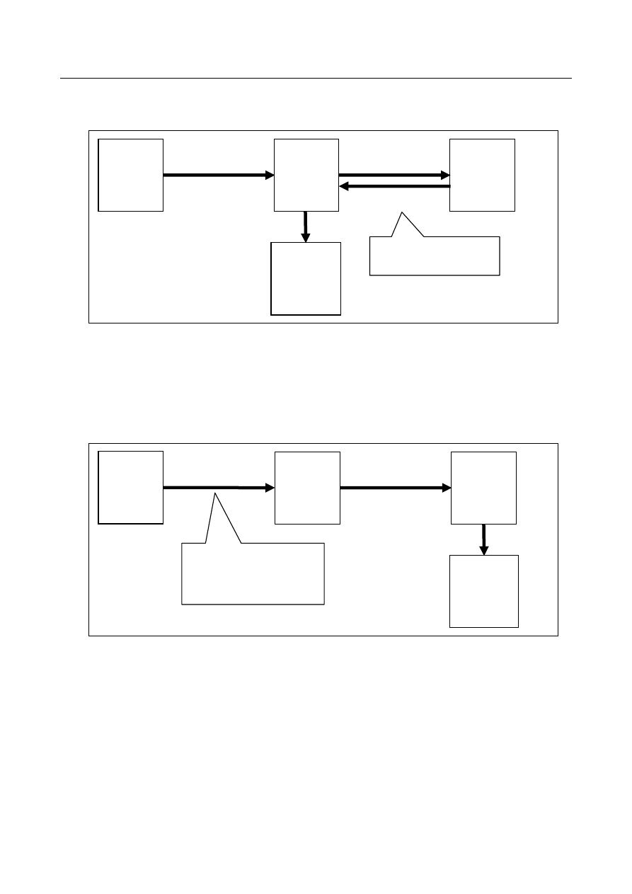
2  If deceleration stops of the axis are executed by feed hold signal, it was necessary to make the PMC 

ladder. The PMC ladder executes the feed hold stop by making feed hold signal *SP <Gn008.5> to 0 
when the power failure detection signals XPFL1 – XPFL8 <Fn374> is 0. 


Fig. 2.13 (d) Deceleration stops of the axis by feed hold signal (PMC ladder)   

 
3  If immediately stops of the axis are executed by emergency stop that uses power failure detection 

signal (contact signal) from the power supply, it was necessary to make the wiring. The wiring wires 
emergency stop *ESP <X8.4>,<X8.0>,<X8.1> of PMC for the power failure detection signal (contact 
signal) from the power supply. 


Wiring effort can be reduced

  by using this function though immediately stops of the axis by the 

following wiring can be achieve the stop at power failure earlier than stop time that used this function. 


Fig. 2.13 (e) Immediately stops of the axis by emergency stop (Wiring for contact signal) 


Power 

supply 


Power failure detection 
signal (contact signal) 

CNC 

PMC 

Servo 

amplifier 

Immediately 

stop 


Emergency stop *ESP 

<X8.4>,<X8.0>,<X8.1> 

The wiring that wires emergency 
stop of PMC for the power 
failure detection signal (contact 
signal)  becomes unnecessary by 
this function. 

Power 

supply 

Power failure 

detection signals 

CNC 

Power failure 

detection signals   

XPFL1 -XPFL8<Fn374> 

PMC 

Servo 

amplifier 

Deceleration 

stop 

Feed hold signal 

*SP<Gn008.5> 

The PMC ladder that executes 
the feed hold stop becomes 
unnecessary by this function. 

B-64693EN-1/01


2. PREPARATIONS FOR OPERATION


- 603 - 

NOTE 

-  Improvement of stop distance reduction function at power failure is valid after the 

servo ready signal SA <Fn000.6> is set to “1” for the first time after power on. 

-  It enters the servo off state at the same time as generating the alarm at the 

immediately stops (alarm SV1094), and it shifts to deceleration stop operation 
with the dynamic brake. In this case, the stopping distance can be shortened by 
using brake control function (bit 6 (BRKCx) of parameter No.2005) and quick stop 
at emergency stop (bit 0 (DBSTx) of parameter No.2017). Refer to Servo motor 
parameter manual (B-65270EN) for details of brake control function and quick 
stop at emergency stop. 

-  This function executes the axis stop directly according to the power failure 

detection signal from power supply without using PMC. Therefore, timing in which 
the axis stop begins is different from conventional stop distance reduction 
function at power failure. Use conventional stop distance reduction function at 
power failure if the axis should stop after operating the machine side according to 
the power failure detection signals XPFL1 – XPFL8 <Fn374>. 


Parameter 


#7 

#6 

#5 

#4 

#3 

#2 

#1 

#0 

2005 


BRKCx 


[Input type]  Parameter input 


[Data type]  Bit axis 


#6  BRKCx

  Brake control function is: 

0: 

Disabled. 

1: 

Enabled. 


#7 

#6 

#5 

#4 

#3 

#2 

#1 

#0 

2017 


DBSTx 


[Input type]  Parameter input 


[Data type]  Bit axis 


#0  DBSTx

  Specifies whether to enable quick stop type 1 at emergency stop as follows: 

0: 

To disable. 

1: 

To enable. 

When using the quick stop at emergency stop function, make the brake control setting for 
all the axes to which thus function is applied. 
 

NOTE 


When only the brake control function is set, a gradual stop occurs 
with the torque limit set by the torque limit setting function during 
brake control. 
When the quick stop at emergency stop is enabled, a gradual stop 
occurs with the torque limit set to 100%, so that the stop distance is 
reduced. 


2. PREPARATIONS FOR OPERATION


B-64693EN-1/01


- 604 - 


#7 

#6 

#5 

#4 

#3 

#2 

#1 

#0 

11808 


PFD 


[Input type]  Parameter input 


[Data type]  Bit path 


#2  PFD

  Improvement of stop distance reduction function at power failure is: 

0: 

Immediately stop (alarm SV1094). 

1: 

Deceleration stop (alarm DS0099). 


#7 

#6 

#5 

#4 

#3 

#2 

#1 

#0 

11820 


PFSx 


[Input type]  Parameter input 


[Data type]  Bit axis 


#1  PFSx

  Improvement of stop distance reduction function at power failure is: 

0: 

Disabled. 

1: 

Enabled. 


Signal 

Emergency stop (input) 

*ESP<X008.4> (for the first machine group), <X008.0> (for the second machine 
group), <X008.1> (for the third machine group), <Gn008.4> 

  [Classification]  Input signal 
 

[Function]  Activating an emergency stop signal stops the machine instantly. 


[Operation]  When the emergency stop signal *ESP turns to “0”, the emergency stop is applied to the 

machine and the CNC is reset. This signal is controlled by the B contacts of a pushbutton 
switch. The emergency stop signal turns the servo ready signal SA to “0”. 
 

Feed hold signal *SP<Gn008.5> 

  [Classification]  Input signal 
 

[Function]  Halts automatic operation. 


[Operation]  When signal *SP is set to 0 during automatic operation, the CNC enters the feed hold 

state and stops operation. Automatic operation cannot be started when signal *SP is set to 
0. 
MEM, RMT, or MDI mode 
 

Servo Ready Signal SA<Fn000.6> 

  [Classification]  Output signal 
 

[Function]  Signal SA turns to “1” when the servo system is ready to operate. For an axis that is to be 

braked, release the brake when this signal is “1” and apply the brake when this signal is 
“0”.   
 

Power Failure Detection Signals XPFL1 to XPFL8<Fn374> 

  [Classification]  Output signal 
 

[Function]  This signal indicates that power failure is detected by the power supply. 


[Operation]  This signal turns to 1 at: 

-


Normal 

The signal turns to 0 at: 
-


Power failure status 


B-64693EN-1/01


2. PREPARATIONS FOR OPERATION


- 605 - 

Signal address 


#7 

#6 

#5 

#4 

#3 

#2 

#1 

#0 

X008 


*ESP 


(*ESP) 

(*ESP) 


Gn008 


*SP 

*ESP 


Fn000 


SA 


Fn374 


XPFL8 

XPFL7 

XPFL6 

XPFL5 

XPFL4 

XPFL3 

XPFL2 

XPFL1 


Alarm and message 


Number 

Message 

Description 

SV1094 

STOP DISTANCE REDUCTION 
ENABLE 

The axis stop is executed by stop distance reduction function at 
power failure. 

DS0099 

STOP DISTANCE REDUCTION 
ENABLE   

The axis stop is executed by stop distance reduction function at 
power failure. 


3. MANUAL OPERATION


B-64693EN-1/01


- 606 - 

MANUAL OPERATION 

3.1 

JOG FEED/INCREMENTAL FEED 

Overview 

  - 

Jog feed 

In jog mode, setting a feed axis and direction selection signal  to “1” moves the tool along the selected 
axis in the selected direction continuously. 
Manual operation is allowed one axis at a time. Up to 3 axes can be selected at a time by setting bit 0 
(JAX) of parameter No.1002. 
By using bit 6 of parameter No. 7001, the number of axes that can be selected can be increased up to the 
maximum number of simultaneously controlled axes. 
 

  - 

Incremental feed 

In incremental feed mode, setting a feed axis and direction selection signal to “1” moves the tool one step 
along the  selected axis in the selected direction. The minimum distance the tool is moved, is the least 
input increment. The step can be 10, 100, or 1000 times the least input increment. 
Bit 2 (HNT) of parameter No. 7103 can be used to multiply the obtained step by 10. 
 

  - 

Feedrate 

The jog feedrate is specified in parameter No.1423. 
The jog feedrate can be adjusted with the jog feedrate override dial. 
With manual rapid traverse selection signal, the tool can be moved at the rapid traverse rate regardless of 
the jog feedrate override signal. 
 

Explanation 

  - 

Manual per revolution feed 

The manual per revolution feed is enabled for jog feed and  incremental feed by setting bit 4 (JRV) of 
parameter No.1402  to 1.  During the manual per revolution feed, jog feed and  incremental feed is 
performed at the feedrate that is obtained by multiplying the spindle speed and the jog feedrate override 
value by the feed amount per revolution specified with the parameter No. 1423. In the case of linear axis 
(metric input), during manual per revolution feed, the tool is jogged at the following feedrate:   
Parameter setting value (mm/rev) 

×

 JOG feedrate override 

×

 actual spindle speed (rev/min). 


NOTE 

1  Manual per revolution feed is not available at the setting of without the position 

coder (setting bit 0 (NPC) of parameter No.1402 to 1 or bit 1 (FPR) of parameter 
No.3729 to 1). 

2  When multi spindle control is enabled and the multiple position coders are used, 

the target feedback pulses from the position coder for manual per revolution feed 
is selected with a position coder select signal (PC2SLC<Gn028.7>, 
PC3SLC<Gn026.0>, PC4SLC <Gn026.1>). And in addition, when multi path 
control is enabled, an arbitrary position coder can be selected by combining a 
path spindle feedback selection signals (SLPCA<Gn064.2>, SLPCB<Gn064.3>, 
SLPCC<Gn403.4>, SLPCD<Gn403.5>). For the selection of a position coder, 
see the section of "Multi spindle" and "Path spindle control". 


B-64693EN-1/01


3. MANUAL OPERATION


- 607 - 

Signal 

The following signals determine that way the jog feed or incremental feed is executed. 

Selection 

Jog feed 

Incremental feed 

Mode selection 

MD1, MD2, MD4, MJ 

MD1, MD2, MD4, MINC 

Selection of the axis to move 

+J1, -J1, +J2, -J2, +J3, -J3, ... 

Selection of the direction to move the axis 

Selection of the move amount 


MP1, MP2 

Selection of feedrate 

*JV0 to *JV15, RT, ROV1, ROV2 

 
The only difference between jog feed and incremental feed is the method of selecting the feed distance. In 
jog feed, the tool continues to be fed while feed axis and direction selection signals are 1: +J1, -J1, +J2, 
-J2, +J3, -J3, etc. In incremental feed, the tool is fed by one step. 
The distance of the step is selected by the manual handle feed move distance selection signals MP1 and 
MP2. 
For the signals selecting the mode, see "Mode Selection Signals."  In selection of the move amount, for 
manual handle feed amount selection signals MP1 and MP2, see "MANUAL HANDLE FEED". In 
selection of feedrate, for rapid traverse override signals ROV1 and ROV2, see “Feedrate Override 
Signals.” 
Other signals are described below. 
 

Feed Axis and Direction Selection Signal +J1 to +J8<Gn100>-J1 to -J8<Gn102> 

  [Classification]  Input signal 
 

[Function]  Selects a desired feed axis and direction in jog feed or incremental feed. The sign (+ or -) 

in the signal name indicates the feed direction. The number following J indicates the 
number of the control axis. 


1 : First axis is fed


2 : Second axis is fed


3 : Third axis is fed


:    : 

8 : Eighth axis is fed


+ : Feed in positive direction


- : Feed in negative direction 

+  J  1


[Operation]  When the jog bit is “1”, the control unit operates as described below. 

When jog feed or incremental feed is allowed, the control unit moves the specified 
axis in the specified direction. In jog feed, the control unit continues to feed the axis 
while the bit is “1”. 


Jog mode 
(TEACH IN JOG mode) 


+J1 


1st axis move 


In incremental feed, the control unit feeds the requested axis by the step distance 
which is specified by the manual handle feed move distance selection signals MP1, 
MP2, then the axis stops. Even if the signal is set to “0” while the axis is being fed, 
the control unit does not stop moving. 


To feed the axis again, set the signal to “0”, then to “1” again.


3. MANUAL OPERATION


B-64693EN-1/01


- 608 - 

  CAUTION 

1  If both the positive direction and negative direction signals of the 

same axis are simultaneously set to “1”, neither the positive 
direction nor the negative direction is selected. The control unit 
assumes that both these signals are set to “0”. 

2  If the feed axis and direction selection signals are set to “1” before 

the jog feed mode or incremental feed mode is selected, these 
signals are invalidated. After the jog feed mode or incremental feed 
mode is selected, set these signal to “0”, then set them to “1” again. 

3  If the control unit is reset while the feed axis and direction selection 

signals are set to “1” or if a feed axis and direction signal turns to 
“1” while the control unit is in the reset state, the signal will be 
ignored even after releasing reset. After the reset state is released, 
set these signals to “0”, then set them to “1” again. 


Jog mode or incremental feed
mode

+J1

1st axis move

Axis is fed again after signals
have turned to "0" once.

+J1 is
ineffective
during this
period.


Jog mode or incremental feed
mode

Reset

+J1

1st axis move

Axis is fed again after
signals have turned to "0"
once.

Move is stopped
by resetting

+J1 is
ineffective
during this
period.


Manual feedrate override signal *JV0 to *JV15<Gn010,Gn011> 

  [Classification]  Input signal 
 

[Function]  Selects a feedrate in jog feed or incremental feed. These signals are in sixteen bit binary 

code, which corresponds to the override values as follows:


=

×

×

15

0

i

2

0.01%

=


(%)


 value

Override

Vi

i


where 

Vi=0 when *JVi is “1”. 


Vi=1 when *JVi is “0”. 

 
The override value is assumed to be zero when all of the signals, (*JV0 to *JV15) are set 
to “1” or “0”. When this occurs, the feed is stopped. The override value can be specified 
in the range of 0% to 655.34% in units of 0.01%. Some examples are listed below. 
 

B-64693EN-1/01


3. MANUAL OPERATION


- 609 - 

*JV0 to *JV15 

Override value 

12 

1  1  1  1 

1  1  1  1 

1  1  1  1 

1  1  1  1 

1  1  1  1 

1  1  0  1 

0  1  1  0 

0  0  0  0 

0  0  0  0 

1  1  1  1 

1  1  1  1 

1  1  1  1 

1  1  1  1 

1  1  0  0 

1  0  0  0 

0  0  1  1 

0  0  0  0 

0  0  0  0 

1  1  1  1 

1  1  1  1 

1  1  1  1 

1  0  0  1 

0  0  0  1 

1  1  1  0 

1  0  1  1 

0  0  0  0 

0  0  0  0 

1  1  1  1 

1  1  1  0 

0  1  0  1 

1  0  1  1 

0  1  1  1 

1  1  1  1 

1  1  1  1 

0  0  0  1 

0  0  0  0 


0.01 


0.10 


1.00 


10.00 


100.00 


400.00 


655.34 


[Operation]  If rapid traverse selection signal RT is “0” during jog feed or incremental feed, actual 

feedrate is manual feedrate set by parameter No.1423 multiplied by override value 
selected by this signals. 


NOTE 


The *JVi signals also serve as the override signals during dry run in 
automatic operation mode. 


Manual rapid traverse selection signal RT<Gn019.7> 

  [Classification]  Input signal 
 

[Function]  Selects a rapid traverse rate for jog feed or incremental feed. 


[Operation]  When the signal turns to “1”, the control unit operates as described below: 

The control unit executes the jog feed or incremental feed at a rapid traverse rate. The 
rapid traverse override is validated. 
When the signal is switched from “1” to “0” or vice versa during jog feed or incremental 
feed, the feedrate is decelerated until it reaches zero, then increased to the specified value. 
During acceleration and deceleration, the feed axis and direction selection signal can be 
kept “1”. 


Jog feed mode or incremental feed mode 


+J1 
 
RT 
 
1st axis move 


Rapid traverse rate 


Feedrate selected by manual feedrate override signal


  WARNING 


After the power is turned on, stored stroke check function does not 
work until the reference position return is completed. During this 
period, the control unit ignores manual rapid traverse selection 
signal RT, if it is set to “1”, and keeps moving the tool at a feedrate 
selected by the manual feedrate override signal. The bit 0 (RPD) of 
parameter No. 1401 can be set so the rapid traverse is validated 
before the reference position return is completed. 


Content      ..     79      80      81      82     ..