Kawasaki Robot Controller F Series. Installation and Connection Manual (2016) - page 3
 

  Index      Manuals     Kawasaki Robot Controller F Series. Installation and Connection Manual (2016)


Search            copyright infringement  


Content      ..     1      2      3      4      ..


Kawasaki Robot Controller F Series. Installation and Connection Manual (2016) - page 3


F Series Controller 

5 Arrangement of Robot Controller 

Kawasaki Robot  Installation and Connection Manual 

28 

Sealed specification 


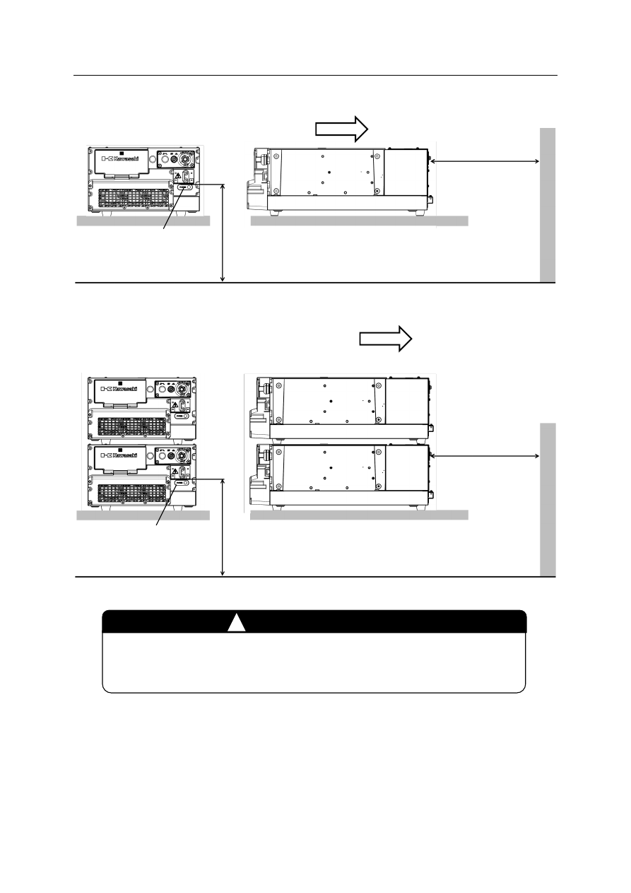
Double stack   

arrangement of controllers 


Direct the airflow avoiding the fan exhaust opening in the rear of the 
controller. Foreign matter can enter from the rear of the controller and 
cause failure. 

CAUTION 


0.6 to 1.9 m 

Controller power 

switch 

200 mm or more 

Airflow direction of fan 


Controller power 

switch 


0.6 to 1.9 m 

200 mm or more 


Airflow direction of fan 


F Series Controller 

5 Arrangement of Robot Controller 

Kawasaki Robot  Installation and Connection Manual 

29 

5.2  Vertical Arrangement of Controller 

Follow the procedure below when arranging the controllers vertically. 


Precautions 

• 

An object cannot be placed on the top surface of the controller when the controllers are 
placed vertically. 


Locations 

• 

Arrange the controller on a flat, horizontal stand and adjust its height so that the heights of 
controller power switch and operation switches from the floor are between 0.6 to 1.9 m. 

• 

Arrange the controller with its controller power switch facing upward. 

• 

Provide a clearance of 200 mm or more between the controller rear side and the wall. 
 

Standard open specification 


Controller power 

switch 

0.6 to 1.9 m 

200 mm or more 

F Series Controller 

5 Arrangement of Robot Controller 

Kawasaki Robot  Installation and Connection Manual 

30 

Sealed specification 


0.6 to 1.9 m 


200 mm or more 

Controller power 

switch 


F Series Controller 

5 Arrangement of Robot Controller 

Kawasaki Robot  Installation and Connection Manual 

31 

5.3  Tap Position on the Side of Controller 

When using the tapped holes below, be careful so that bolts do not interfere with internal 
parts. 
See figures below for lengths of bolts to be used. (Tapped size: M5) 


F60 controller   


Standard open specification 


• 

Sealed specification 


18 

141.2 

52.5 

52.5  95 

95  52.5 

52.5 

141.2 

141.2 

141.2 

277.5 

277.5 

18 

F Series Controller 

5 Arrangement of Robot Controller 

Kawasaki Robot  Installation and Connection Manual 

32 

E.g.)  The bolt length is 15 mm or less when fixing the controller on the plate whose 

thickness is 2 mm. 


Side wall of 

controller 

Bolt length

15 mm 

Spot facing size (common in 8 places) 

  Diameter: 

φ

13 mm 

  Depth: 

3.5 mm 

Plate 

F Series Controller 

6 Connection Instructions 

Kawasaki Robot  Installation and Connection Manual 

33 

6  Connection Instructions 

6.1  Connection between Controller and Robot 

Strictly observe the following precautions when connecting the robot with the controller. 


In order to prevent electric shock accidents, do not connect the external 
power until connections between the robot and the controller are complete. 

WARNING 


F Series Controller 

6 Connection Instructions 

Kawasaki Robot  Installation and Connection Manual 

34 


CAUTION 

1.  Do not mistake the destination of connectors when connecting the 

harnesses. Forcing to connect the harness wrongly may damage 
connectors or cause a break in the electrical system. 

2.  Prevent people or equipment (forklift etc.) from stepping on or riding 

over the harnesses. Otherwise, the harness may become damaged or 
the electrical system may break. 

3.  Separate the harnesses from any nearby high voltage lines. 

(1)  Do not run the harnesses in parallel with other power lines. 
(2)  Do not bundle the harnesses. 
(3)  Separate the harnesses for 1 m or more from any nearby high 

voltage/high current power lines. Otherwise, the noise is 
generated from power lines and will cause malfunctions. 

4.  Even when the harnesses are long, do not bundle them winded or 

bended. Bundling the harness causes the heat to build up in the 
harness, resulting in over-heat and furthermore may cause fire. 

5.  Separate the motor harness from the communication and sensor 

cables, and distribute the lines. 
(1)  Do not run the harnesses in parallel with cables. 
(2)  Do not bundle the harnesses. 

6.  Connect the communication and sensor cables using shield mesh wire 

that includes twisted pair lines and connect the mesh wire properly. 
Otherwise, PWM noise may penetrate into various cables, such as 
communication cable and cause communication errors. 

7.  Separate the welder secondary cable from the robot’s signal harness. 

Do not wire them in the same duct. 

8.  Strictly observe the following precautions so that PWM noise 

generated from the motor harness (power line) does not interfere with 
control signal lines. 
(1)  Separate the power and signal lines. 
(2)  Use the shortest length for the power line. 
(3)  Do not bundle or run the harnesses in parallel with the signal line. 
(4)  Do not wire the power and signal line within the same 

duct/conduit. 

(5)  Set and secure a firm ground line connection for the controller. 


F Series Controller 

6 Connection Instructions 

Kawasaki Robot  Installation and Connection Manual 

35 


Connecting place 

Connect the separate harnesses to their designated ports as shown below. 


• 

Controller side 


Signal harness (X3) 

Motor harness (X4) 

Brake output harness (X4) 

Brake output connector 

Motor power 

connector 

(Jt2,4,6) 

Motor power 

connector 

(Jt1,3,5) 

Cable shield 

*For Jt7 

Bundle motor power 

connector and brake 

output connector. 

CAUTION 

1.  Fix each connector securely. The robot may malfunction if connectors 

detach. 

2.  When placing a controller on another controller, connect the separate 

harnesses so that they do not block the exhaust port of the bottom 
controller. 


F Series Controller 

6 Connection Instructions 

Kawasaki Robot  Installation and Connection Manual 

36 

To make the standard F60 open structure controller comply with the UL standard, attach the 
connector covers in the rear of the controller, following the instructions below.*


The F60 sealed specification controller does not require the connector cover. 

 
1.  Attach the connector cover mounting metal plates to the rear of the controller. 


2.  Insert the connectors of the motor harnesses and power cable into the controller. 
3.  Attach the connector covers. 


Connector cover mounting 

metal plate 

(XPOW connector) 

Screw 

Screw 

Connector cover mounting 

metal plate 

(XMOTA/XMOTB connector) 

Screw 

Connector cover 

(XMOTA/XMOTB) 

Connector cover 

(XPOW connector) 

Screw 

Motor harness 

Power cable 

F Series Controller 

6 Connection Instructions 

Kawasaki Robot  Installation and Connection Manual 

37 

Connect the harnesses for the F60 sealed specification, following the instructions below. 
1.  Connect the harnesses following the procedure below. 

(1)  Remove the eight rear unit cover fixing screws of the sealed chassis, and remove the 

cover. 

(2)  Connect the harness connectors to the controller body. 
(3)  Secure the harnesses to the harness seal packing in the sealed chassis rear unit body. 
(4)  Attach the sealed chassis unit cover and secure it with the eight screws. 


Front view of sealed chassis rear unit body 


Top view of sealed chassis rear unit body 

Screw 

Screw 

Screw 

Screw 

Sealed chassis rear unit 

cover 

Harness seal packing 

Sealed chassis rear unit 

body 

Screw 

Screw 

Screw 

Screw 

F Series Controller 

6 Connection Instructions 

Kawasaki Robot  Installation and Connection Manual 

38 

2.  Secure each harness at the predetermined location of the harness seal packing of the 

sealed chassis rear unit body as shown in the figure below. 


No. 

Symbol 

Harness name 

Specified cable 

diameter 

XMOT (A) 

External axis (JTA) motor harness 

8.1±0.5 mm 

XMOT (B) 

External axis (JTB) motor harness 

8.1±0.5 mm 

XPOW 

Power cable 

11.4±0.4 mm 

XRLS 

Brake release harness 

10.3±0.8 mm 

XSIG (A) 

External axis (JTA) signal harness 

7.3±0.2 mm 

XSIG (B) 

External axis (JTB) signal harness 

7.3±0.2 mm 

XRSIG 

Arm signal harness 

10.3±0.3 mm 

XTP 

TP cable 

9.4±0.5 mm 

XSW 

External operation panel cable 

5.6±0.4 mm 

10 

XGPIO 

General I/O signal cable 

8.1

±

0.5 mm

*2


11 

XMOT 

Arm motor harness 

19.1±0.5 mm 

12

*1


OP 


12

±

0.5 mm

*2


13

*1 

OP 


12

±

0.5 mm

*2


*1 

Use for options other than those listed above 

*2

 Use cables with the specified cable diameter listed. 

Specification 

for cables 

provided by 

KHI 

(1)  (2)  (3)  (4)  (5)  (6)  (7)  (8) 

(10) 

(9) 

(12) 

(11) 

Harness seal 

packing 

Sealed chassis 

rear unit body 

(13) 

F Series Controller 

6 Connection Instructions 

Kawasaki Robot  Installation and Connection Manual 

39 

If there is any unused harness in the list above, fit a plastic sealing stopper provided as an 
accessory into the harness seal packing for the unused harness. The sealing stoppers have 
the harness codes written on them so that the right stoppers can be placed in the right 
attachment points. See below for how to insert the sealing stoppers. 


Sealing 

stoppers 

Sealing stopper (insert with 

the lettering facing out from 

the chassis) 

Harness seal packing 

Use the correct sealing 

stopper 

Fixing metal 

plate of 

packing 

Harness seal 

packing 

F Series Controller 

6 Connection Instructions 

Kawasaki Robot  Installation and Connection Manual 

40 

3.  When securing each harness to the harness seal packing of the sealed chassis rear unit 

body, be careful that the packing has not caught on the side of the cable as shown below. 


Cable correctly inserted 

Cable incorrectly inserted 


4.  When removing the harness from the harness seal packing for replacement or other 

reasons after the harness has been attached in the sealed chassis rear unit body, replace 
the harness seal packing with a new one, following the procedure below. 

(1) Remove the four screws from the harness seal packing fixing metal plate, and replace 

the harness seal packing with a new one. 


Rear view of the sealed chassis rear cover 


Cable 

Packing 

Packing is caught on the side of the cable 

Fixing metal plate 

of packing 

Harness seal 

packing 

Screw 

Screw 

Screw 

Screw 

F Series Controller 

6 Connection Instructions 

Kawasaki Robot  Installation and Connection Manual 

41 

(2)  Remove the eight screws from the harness seal packing fixing metal plate of packing, 

and replace the harness seal packing with a new one. 


Top view of sealed chassis rear unit body 


5.  Secure the ferrite core on the XMOT harness in the correct position as shown the figure 

below. 


Top view of sealed chassis rear unit body 


View A 


Fixing metal plate 

of packing 

Harness seal 

packing 

Screw 

Screw 

Screw 

Screw 

Screw 

Screw 

Screw 

Screw 

Ferrite core 

mounting cover 

Ferrite core 

Aluminum block 

Screw to attach cable shield 

Ferrite core 

mounting  cover 

Screw (M3, P4 L=6   

Tightening torque: 

0.7 N·m) 

F Series Controller 

6 Connection Instructions 

Kawasaki Robot  Installation and Connection Manual 

42 

6.  Use the positions shown below to attach the harness shield terminals to the controller. 


Left view 

Top view 

Right  view 


Expanded view of sealed chassis rear unit body 


Read the precautions carefully before attaching separate harnesses. 
If attached incorrectly, dirt and dust, etc., could get into the controller 
and cause malfunction or breakdown. 

CAUTION 


XMOT (B) shield 

XMOT (A) shield 

XMOT shield 

Other shields 

F Series Controller 

6 Connection Instructions 

Kawasaki Robot  Installation and Connection Manual 

43 

• 

Arm side 

–  Cable diameter 

Motor harness: 18.6 to 19.6 mm, Signal harness: 10.0 to 10.6 mm 


R series: 03N/05N/05L 

R series: 10N/06L 


R series: 07N/07L 

BA 


Signal harness 

Motor harness 

Motor harness 

Signal harness 

Signal harness 

Motor harness 

Signal harness 

Motor harness 


Content      ..     1      2      3      4      ..