Cisco IE 4010 Switch Hardware Installation Guide (2019) - page 1
Cisco IE 4010 Switch Hardware Installation
Guide
First Published: September 2016
Last Updated: September 2019
Preface
Audience
This guide is for the networking or computer technician responsible for installing Cisco IE 4010 series switches. We
assume that you are familiar with the concepts and terminology of Ethernet and local area networking.
Purpose
This guide documents the hardware features of the Cisco IE 4010 switches. It describes the physical and performance
characteristics of each switch, explains how to install a switch, and provides troubleshooting information.
This guide does not describe system messages that you might receive or how to configure your switch. For more
information, see the Cisco IE4010 documentation at
ies-home.html
For information about the standard Cisco IOS commands, see
Conventions
This document uses the following conventions and symbols for notes, cautions, and warnings.
Note: Means reader take note. Notes contain helpful suggestions or references to materials not contained in this manual.
Caution: Means reader be careful. In this situation, you might do something that could result in equipment damage
or loss of data.
Warning: This warning symbol means danger. You are in a situation that could cause bodily injury. Before you work
on any equipment, be aware of the hazards involved with electrical circuitry and be familiar with standard practices
for preventing accidents. Use the statement number provided at the end of each warning to locate its translation in
the translated safety warnings that accompanied this device. Statement 1071
The safety warnings for this product are translated into several languages in the Cisco IE 4010 Switch Product Document
of Compliance that ships with the product. The EMC regulatory statements are also included in that guide.
Related Publications
Before installing, configuring, or upgrading the switch, see the release notes on Cisco.com for the latest information.
These documents provide complete information about the switch and are available on Cisco.com:
Regulatory Compliance and Safety Information for the Cisco IE 4010 Switch
Release Notes for the Cisco IE 4010 Switch
iii
Obtaining Documentation, Obtaining Support, and Security Guidelines
Cisco IE 4010 Switch Software Configuration Guide
Device Manager Online help (available on the switch)
These compatibility matrix documents are available from this Cisco.com site:
Cisco Gigabit Ethernet Transceiver Modules Compatibility Matrix (not orderable but available on Cisco.com)
Cisco Small Form-Factor Pluggable Modules Compatibility Matrix (not orderable but available on Cisco.com)
Obtaining Documentation, Obtaining Support, and Security
Guidelines
For information on obtaining documentation, obtaining support, providing documentation feedback, security guidelines,
and also recommended aliases and general Cisco documents, see the monthly What’s New in Cisco Product
Documentation, which also lists all new and revised Cisco technical documentation, at:
iv
Product Overview
The Cisco IE 4010 switch provides a rugged and secure switching infrastructure for harsh environments. It is suitable for
industrial Ethernet applications, including process manufacturing, utility substations, intelligent transportation systems
(ITSs), rail transportation, and other similar deployments.
In industrial environments, you can connect the switch to any Ethernet-enabled industrial communication devices,
including programmable logic controllers (PLCs), human-machine interfaces (HMIs), drives, sensors, and input and
output (IO) devices.
In utility substations the switch can connect to devices such as Intelligent Electronic Devices (IEDs), distributed
controllers, substation routers, Cisco IP Phones, Cisco Wireless Access Points, and other network devices such as
redundant substation switches.
For detailed specifications, see the IE 4010 Data Sheet.
Switch Models, page 1
Cable Side, page 2
Power-Supply Side, page 10
Management Options, page 12
Switch Models
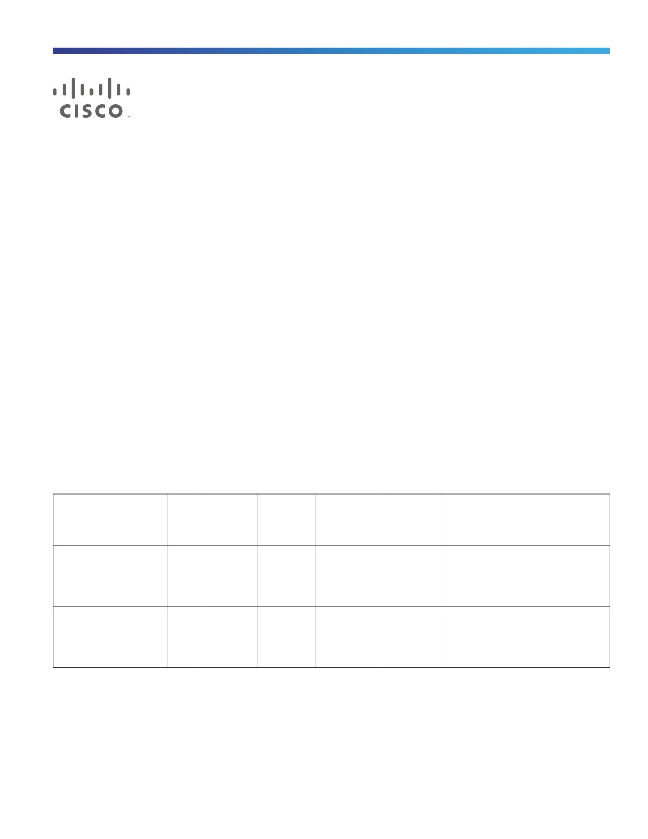
Table 1
Switch Models
Model
Total
Uplinks
SFP Fiber
Copper
Default
Power Supplies
Ports
Ports
10/100/1000
Software
PoE/PoE+
License
Ports1
IE-4010-16S12P
28
4 SFP
12
12
LAN
Support for 2 field-replaceable,
(100MB/
(100/1000
(10/100/100
Base2
redundant AC or DC power supplies.
1G)
M)
0M)
For detailed specifications, see
Table 16 on page 72.
IE-4010-4S24P
28
4 SFP
24
LAN Base
Support for 2 field-replaceable,
(100MB/
(10/100/100
redundant AC or DC power supplies.
1G)
0M)
For detailed specifications, see the
Table 16 on page 72.
1. All copper Gigabit Ethernet interfaces support speed negotiation to 10/100/1000 mbps and duplex negotiation.Ethernet 4010 Series.
2. Can be upgraded to IP Services at a fee. IP Services License Product Numbers are the following: L-IE4000-RTU= (Electronic SW
License for IE4000 Switches)
1
Product Overview
Cable Side
Cable Side
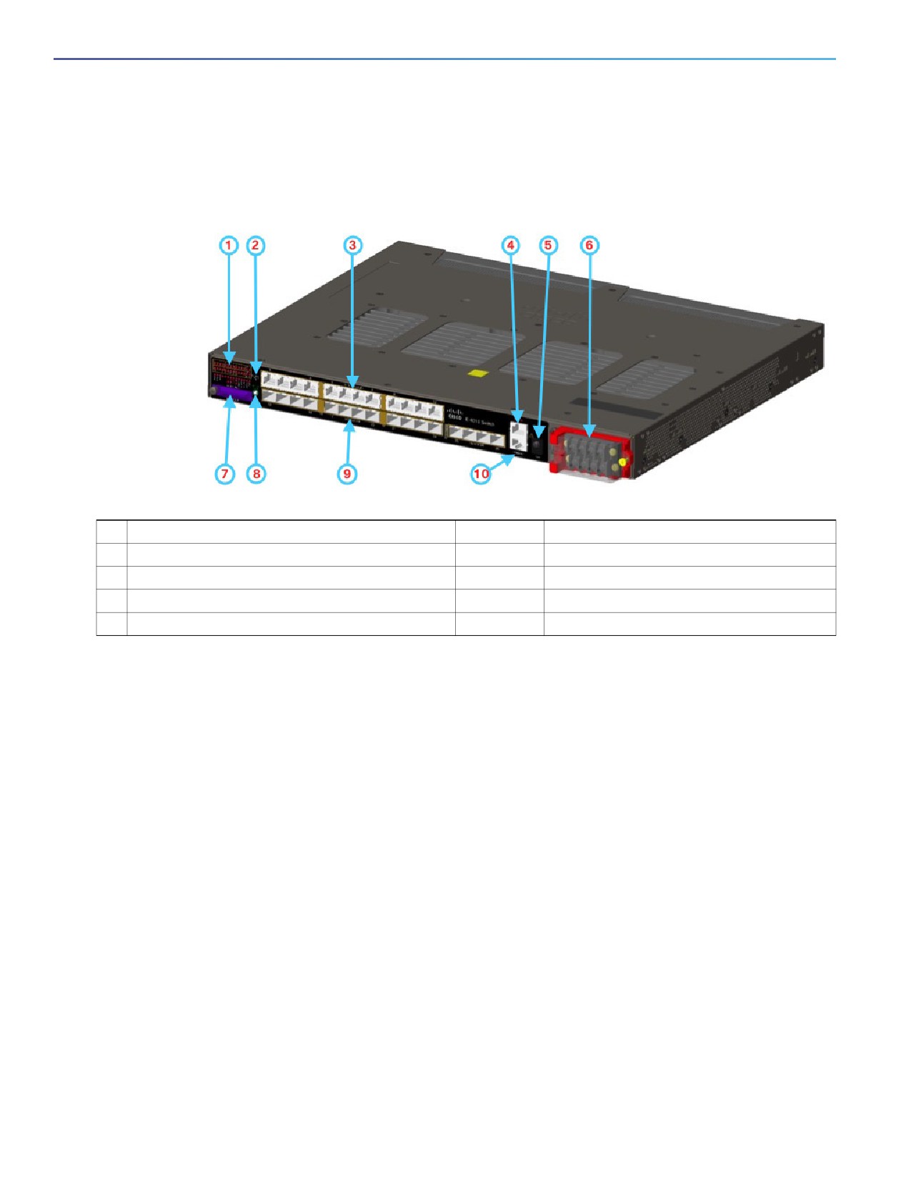
Figure 1
Cisco IE-4010-16S12P Cable-Side View
1
LEDs
6
Power-input terminal
2
Express Setup button
7
Flash memory card slot
3
Twelve 10/100/1000 PoE/PoE+ Ports (Downlinks)
8
Display mode button
4
Alarm port
9
Twelve 100/1000 SFP Ports
5
USB (mini-Type B) console port
10
Console port
LEDs
For detailed information about LEDs see LEDs, page 5.
10/100/1000 PoE/PoE+ Ports (Downlinks)
You can set the 10/100/1000 ports on the switch to operate in any combination of half duplex, full duplex, or 10 or 100
Mb/s. You can set the ports for speed and duplex autonegotiation. The default setting is autonegotiate.
When set for autonegotiation, the switch determines the speed and duplex settings of the attached device and advertises
its own capabilities. If the connected device also supports autonegotiation, the switch negotiates the best connection
(the fastest line speed that both devices support and full-duplex transmission if the attached device supports it) and
configures itself accordingly. In all cases, the attached device must be within 328 feet (100 meters).
Warning: Voltages that present a shock hazard may exist on Power over Ethernet (PoE) circuits if interconnections
are made using uninsulated exposed metal contacts, conductors, or terminals. Avoid using such interconnection
methods, unless the exposed metal parts are located within a restricted access location and users and service
people who are authorized within the restricted access location are made aware of the hazard. A restricted access
area can be accessed only through the use of a special tool, lock and key or other means of security. Statement
1072
The 10/100/1000 PoE ports on the Cisco IE-4010 switches provide PoE support for devices that are compliant with IEEE
802.3af/802.3at. The Cisco prestandard PoE is also supported for Cisco IP Phones and Cisco Aironet Access Points. The
PoE ports on the switch deliver up to 30 W of PoE+ power. All twelve ports are PoE ports and can be assigned a port
priority.
2

Product Overview
Cable Side
When both power-supply modules are installed, the system has enough power to support all twelve ports as PoE ports.
The maximum available PoE power is 200W.
With one power module installed, the maximum available PoE power is 80W. In case one power-supply modules fails,
the power to the low priority PoE ports is dropped, while power to the high priority PoE ports remains uninterrupted.
On a per-port basis, you control whether or not a port automatically provides power when an IP phone or an access point
is connected.
The 10/100/1000 PoE ports use RJ-45 connectors with Ethernet pinouts. The maximum cable length is 328 feet (100
meters). The 100BASE-TX and 1000BASE-T traffic requires CA5, CAT5e, or CAT6 unshielded twisted pair (UTP) cable.
The 10BASE-T traffic can use CAT3 or CAT4 UTP cable.
For information about configuring and monitoring PoE ports, see the switch software configuration guide on Cisco.com.
For information about port connections and port specifications, see Connecting Devices to the Ethernet Ports, page 31.
Note: The output of the PoE circuit has been evaluated as a Limited Power Source (LPS) per IEC 60950-1.
Alarm Ports
The switch has four alarm inputs and one alarm output.
Alarm Input
The alarm input is a dry-contact alarm port. You can connect up to four alarm inputs from devices, such as a door, a
temperature gauge, or a fire alarm, to the alarm port. You can use the CLI to set the alarm severity to minor, or major. An
alarm generates a system message and turns on an LED. See the Alarm LEDs, page 9 for the LED descriptions.
Alarm Output
The alarm output can be configured as a major alarm. Output alarms often control an external alarm, such as a bell or a
light. To connect an external alarm device to the relay, you connect two relay contact wires to complete the electrical
circuit. See for information on the alarm pinouts. see the Alarm Port, page 54.
Mini USB Port
Note: The 5-pin mini-Type B connectors resemble the 4-pin mini-Type B connectors. They are not compatible. Use only
the 5-pin mini-Type B.
Figure 2
USB Mini-Type B Port
The configurable inactivity timeout reactivates the RJ-45 console port if the USB console port is activated, but no input
activity occurs on it for a specified time period. When the USB console port deactivates due to a timeout, you can restore
its operation by disconnecting and reconnecting the USB cable. For information on using the CLI to configure the USB
console interface, see the switch software guide.
3
Product Overview
Cable Side
SD Flash Memory Card
The switch supports a flash memory card that makes it possible to replace a failed switch without reconfiguring the new
switch. The slot for the flash memory card is on the front of the switch. The flash card is hot swappable and can be
accessed on the front panel in non hazardous locations only. A cover protects the flash card and holds the card firmly in
place. The cover is hinged and closed with a captive screw. This prevents the card from coming loose and protects
against shock and vibration.
For more information on inserting and removing the flash memory card, see Power-Supply Side, page 10.
Display Mode Button
For detailed functionality see Display Mode Button, page 8.
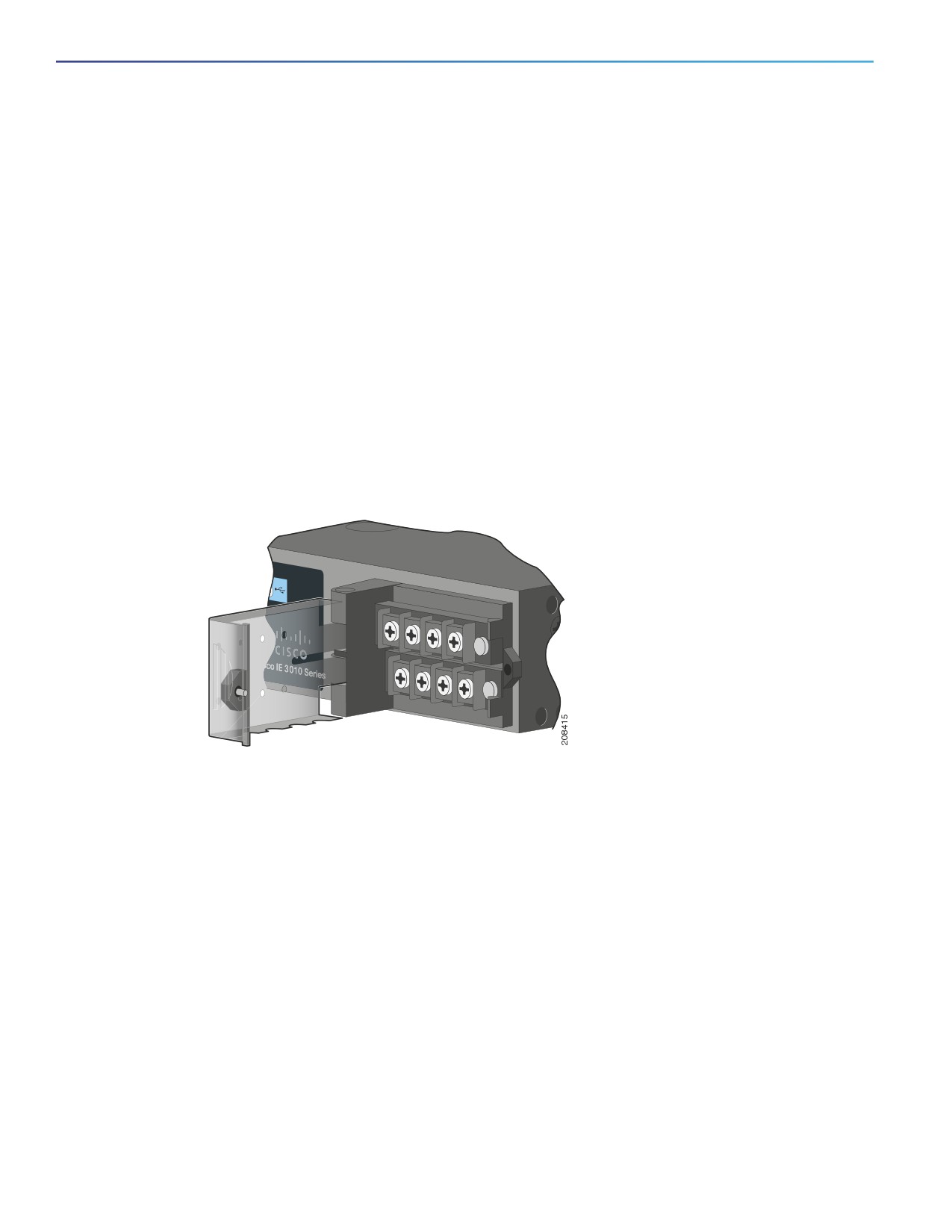
Power-Input Terminal
The power-input terminal provides screw terminals for the AC and DC power connections. The switch can operate with
one or two power supplies. If one of the power sources fail, the other continues to power the switch. See Power Supply
Installation, page 33 for information.
Figure 3
Power-Input Terminal
100/1000 SFP Ports
The switch Ethernet SFP modules provide connections to other devices. These field-replaceable transceiver modules
provide the interfaces. The IE 4010 supports both FE and GE optics. SFP modules have local connectors (LCs) for
fiber-optic connections or RJ-45 connectors for copper connections.
For the most up-to-date list of supported SFP models, see the IE 4010 Data Sheet.
For information about SFP modules, see your SFP module documentation and the Installing and Removing SFP Modules,
page 26. For more information about SFP/SFP+ modules and cables, see Transceiver Modules.
Console Ports
You can connect the switch to a PC running Microsoft Windows or to a terminal server through either the RJ-45 console
port or the USB console port.
RJ-45 console port. The RJ-45 connection uses an RJ-45-to-DB-9 female cable.
USB mini-Type B console port (5-pin connector). The USB connection uses a USB Type A-to-5-pin mini-Type B
cable.
4
Product Overview
Cable Side
The USB console interface speeds are the same as the RJ-45 console interface speeds.
To use the USB console port, you must install the Cisco Windows USB device driver on the device that is connected to
the USB console port (device running with Microsoft Windows). See Installing the Cisco Microsoft Windows XP, 2000,
Vista, 7, 8, and 10 USB Device Driver, page 64 for more information.
With the Cisco Windows USB device driver, connecting and disconnecting the USB cable from the console port does not
affect Windows HyperTerminal operations. Mac OS X or Linux require no special drivers.
LEDs
You can use the switch system and port LEDs to monitor switch activity and performance.
5
Product Overview
Cable Side
Switch Panel LEDs
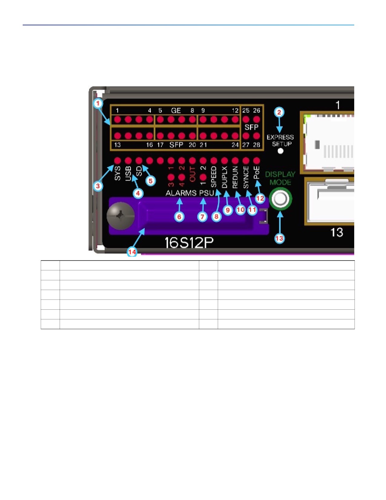
Figure 4
Switch LEDs (Cable Side)
1
Port Status LEDs 1-28
8
Port speed status
2
Express Setup button
9
Port duplex status
3
SYS (system)
10
Redundancy status
4
USB (mini-USB console)
11
Synchronous Ethernet status
5
SD (SD flash memory card)
12
PoE
6
Alarm Status (1 to 4 and Output).
13
Display mode switch
7
PSU1 and 2 (power supply 1 and 2)
14
SD card slot cover
Port LEDs
Each Ethernet port has a port LED. These port LEDs, display information about the individual ports. The port mode
determines the type of information shown by the port LEDs. Table 2 on page 7 lists the mode LEDs and their associated
port modes and meanings.
To select or change a mode, press the Mode button until the desired mode is highlighted. The Mode LED will turn ON
solid green when a mode is selected and turn OFF when timeout (5 seconds) or a different mode is selected. When you
change port modes, the meanings of the port LED colors also change. Table 3 on page 7 explains how to interpret the
port LED colors in different port modes.
6

Product Overview
Cable Side
Table 2
Port Mode LEDs
Mode LED
Port Mode
Description
All Off
Port status
The port status. This is the default mode.
SPEED
Port speed
The port operating speed: 10, 100, 1000 mbps or 10 Gbps.
DUPLX
Port duplex mode
The port duplex mode: full duplex or half duplex.
REDUN
Redundancy status
Parallel Redundancy Protocol (PRP) status.
SYNCE
Synchronous Ethernet
Not supported by software yet. Mode button skips this LED.
status
PoE
PoE+ port power
The PoE+ port status.
Table 3
Meaning of Switch LED Colors in Different Modes
Port Mode LED
Port LED Color
Meaning
All Off
Off
No link, or port was administratively shut down.
Green
Link present, no activity.
Blinking green
Activity. Port is sending or receiving data.
Alternating
Link fault. Error frames can affect connectivity, and errors such as excessive
green-amber
collisions, CRC errors, and alignment and jabber errors are monitored for a
link-fault indication.
Amber
Port is blocked by Spanning Tree Protocol (STP) and is not forwarding data.
After a port is reconfigured, the port LED can be amber for up to 30 seconds as
STP checks the switch for possible loops.
SPEED
10/100/1000/SFP ports
Downlink Ports
Off
Port is not operating.
Amber
Port is operating at 10 Mb/s.
Green
Port is operating at 100 Mb/s.
Flashing green
Port is operating at 1000 Mb/s.
Uplinks Ports
Green
Port is operating at 1000 Mb/s.
DUPLX
Off
Port is not operating.
(duplex)
Amber
Port is operating in half duplex.
Green
Port is operating in full duplex.
REDUN
Green
One or more redundancy protocols are configured and active (for example, HSR,
DLR, PRP, etc.)
Blinking amber
One or more redundancy protocols are indicating a redundancy fault.
Fast blinking green
The port LEDs are showing ports that are participating in a redundancy protocol
and the redundancy fault status of that port.
SYNCE
Off
7

Product Overview
Cable Side
Table 3
Meaning of Switch LED Colors in Different Modes (continued)
Port Mode LED
Port LED Color
Meaning
PoE/PoE+
Off
PoE/PoE+ is off.
If the powered device is receiving power from an AC power source, the port LED
is off even if the device is connected to the switch port.
Green
PoE/PoE+ is on and all ports function correctly. The port LED is green when the
switch port is providing power.
Alternating green
PoE/PoE+ is on but one of the low priority ports power is disconnected or failed.
and amber
Blinking amber
PoE/PoE+ is on but one of the high priority ports power is disconnected or failed.
PoE+ faults occur when noncompliant cabling or powered devices are connected
to a PoE+ port. Use only standard-compliant cabling to connect Cisco prestandard
IP Phones and wireless access points or IEEE 802.3af/at-compliant devices to
PoE+ ports. You must remove from the network any cable or device that causes a
PoE+ fault.
Amber
PoE/PoE+ is on with failures.
PoE+ is enabled by default.
Display Mode Button
The Display Mode Button allows you to choose the mode you want displayed by the port LEDs (items 1-3 in Figure 4 on
page 6). The LEDs with green text to the left of the Button indicate the chosen display mode. Each time you press the
switch, the mode indicator moves from SPEED, DUPLX, REDUN, SYNCE, and PoE respectively.
Power-Supply Module LEDs
The switch power-supply module LEDs are labeled PSU1 and PSU2 (on the switch) and PSU OK (on the power-supply
module). They show whether power-supply modules 1 and 2 are receiving power.
Table 4
Power Supply Module LEDs
Color
System Status
Off
Power-supply module (1 or 2) is not installed.
Green
Valid input is present, and the output is within the operating range.
Red
Valid input is present, and the output is outside the operating range or is not present.
Blinking red
Power-supply module (1 or 2) is installed but valid input is not present.
8

Product Overview
Cable Side
Alarm LEDs
Table 5
Alarm LEDs
Color
System Status
1-4 Input Alarms
Green
Alarm not present
Red
Minor alarm present
Blinking red
Major alarm present
Output Alarm
Green
Alarm not present
Red
Alarm condition present
SD Flash Memory Card LED
Table 6
SD Flash Card LED
Color
System Status
Fast blinking amber
Unsupported SD flash memory card is detected.
Slow blinking amber
SD flash memory card is not present.
Green
SD flash memory card is functioning.
Blinking green
SD flash memory card transfer in progress.
USB LED
The USB LED indicates the console port is in use.
If you connect a cable to the console port, the switch automatically uses that port for console communication. If you
connect two console cables, the USB console port has priority.
Table 7
USB LED
LED
Color
Description
USB console port
Green
USB console port selected
Off
RS232 Console selected
9
Product Overview
Power-Supply Side
System LED
Table 8
System LED
Color
System Status
Off
System is not powered on.
Blinking green
Power-On Self-Test (POST) is in progress.
Green
System is operating normally.
Red
System is receiving power but is not functioning properly.
Power-Supply Side
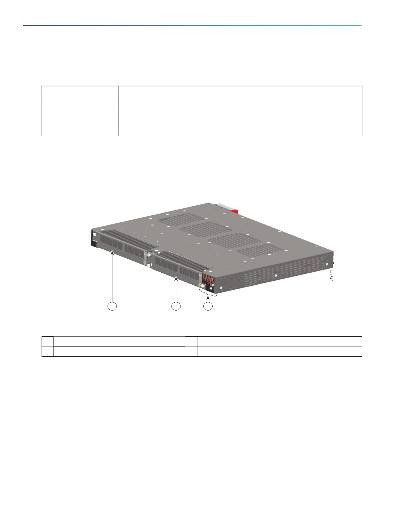
The power-supply side has the LED panel and two power-supply slots for the removable power supplies.
Figure 5
Switch with Both Power-Supply Modules
1
2
3
1
Power Supply slot 1
2
Power Supply slot 2
3
LED panel
10
Product Overview
Power-Supply Side
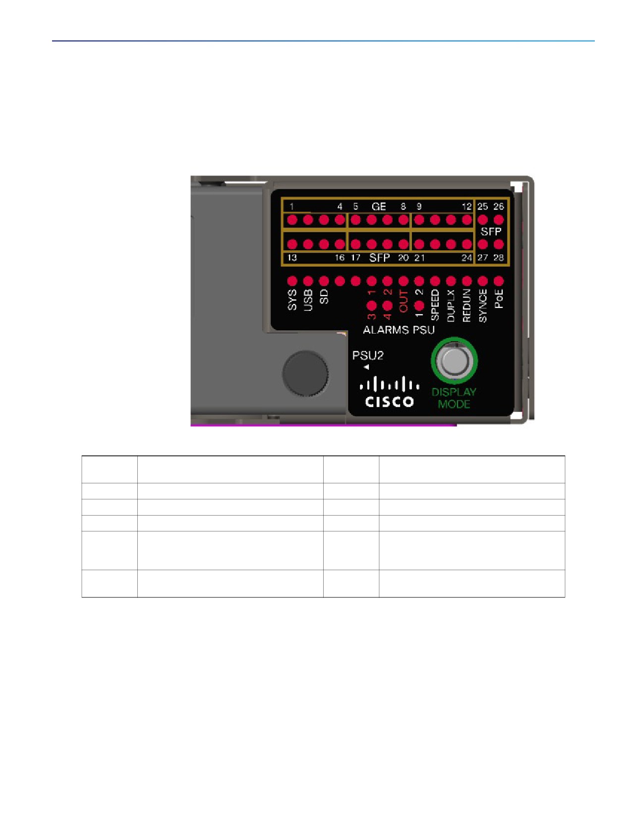
Power-Supply Side LEDs (Similar to Figure 4Switch LEDs (Cable Side),
page 6)
Figure 6
Switch LEDs
1-28
Port (Ethernet and SFP respectively)
SPEED
Port speed status
Status LEDs
SYS
System Status
DUPLX
Port duplex status
USB
Mini-USB console port status
REDUN
Redundancy status
SD
SD flash memory card status
SYNCE
Synchronous Ethernet status
Alarms
Alarm ports and Alarm Output status
PoE
PoE
1-4 and
OUT
PSU 1-2
Power supply 1and 2 status
DISPLAY
Display Mode button
MODE
For more information about these LEDs, see Switch Panel LEDs, page 6.
Power Supply Features
The switch has two slots for power-supply modules:
PWR-RGD-LOW-DC-H: low-voltage DC
PWR-RGD-AC-DC-H: high-voltage AC or DC
Note: For detailed specifications, see the IE 4010 Data Sheet.
11
Product Overview
Management Options
Caution: Only the -H version power supplies are certified safe for hazardous environments.
The switch supports these power-supply module combinations:
Single low-voltage DC
Single high-voltage AC or DC
Two high-voltage AC or DC
Two low-voltage DC
One high-voltage AC or DC and one low-voltage DC
For information on installing the power-supply modules, see Power Supply Installation, page 33.
See Power-Supply Module LEDs, page 8 for information on the power supply LEDs.
Management Options
Cisco IOS CLI
You can configure and monitor the switch from the CLI. Connect your management station to the switch console port
or use Telnet from a remote management station. See the switch command reference on Cisco.com for information.
SNMP network management
You can manage switches from a Simple Network Management Protocol (SNMP)-compatible management station.
The switch supports a comprehensive set of Management Information Base (MIB) extensions and four Remote
Monitoring (RMON) groups. See the switch software configuration guide on Cisco.com and the documentation that
came with your SNMP application for information.
Device Manager
You can use Device Manager, which is in the switch memory, to manage individual and standalone switches. This
web interface offers quick configuration and monitoring. You can access Device Manager from anywhere in your
network through a web browser. For more information, see the Device Manager online help.
Prime Infrastructure
Cisco Prime Infrastructure simplifies the management of wireless and wired networks. It offers Day 0 and 1
provisioning, as well as Day N assurance from the branch to the data center. We call it One Management. With this
single view and point of control, you can reap the benefits of One Management across both network and compute.
Network Configurations
See the switch software configuration guide on Cisco.com for an explanation of network configuration concepts. The
software configuration guide also provides network configuration examples for creating dedicated network segments
that are interconnected through Ethernet connections.
12
Switch Installation
Read the topics and perform the procedures in this order:
Warnings, page 13
Installation Guidelines, page 14
Verifying Switch Operation, page 14
Installing the Switch, page 15
Installing and Removing SFP Modules, page 26
Replacing the SD Flash Memory Card, page 30
Connecting Devices to the Ethernet Ports, page 31
Where to Go Next, page 32
Warnings
These warnings are translated into several languages in the Regulatory Compliance and Safety Information for the Cisco
IE 4010 Switch document.
These warning statements apply to all the switches:
Warning: Before working on equipment that is connected to power lines, remove jewelry (including rings,
necklaces, and watches). Metal objects will heat up when connected to power and ground and can cause serious
burns or weld the metal object to the terminals. Statement 43
Warning: Read the installation instructions before you connect the system to its power source. Statement 1004
Warning: This unit is intended for installation in restricted access areas. A restricted access area can be accessed
only through the use of a special tool, lock and key, or other means of security. Statement 1017
Warning: This equipment must be grounded. Never defeat the ground conductor or operate the equipment in the
absence of a suitably installed ground conductor. Contact the appropriate electrical inspection authority or an
electrician if you are uncertain that suitable grounding is available. Statement 1024
Warning: This unit might have more than one power supply connection. All connections must be removed to
de-energize the unit. Statement 1028
Warning: Only trained and qualified personnel should be allowed to install, replace, or service this equipment. Statement
1030
Warning: Ultimate disposal of this product should be handled according to all national laws and regulations.
Statement 1040
Warning: For connections outside the building where the equipment is installed, the following ports must be
connected through an approved network termination unit with integral circuit protection.
10/100/1000 Ethernet Statement 1044
13
Switch Installation
Installation Guidelines
Warning: To prevent the system from overheating, do not operate it in an area that exceeds the maximum
recommended ambient temperature of:
140°F (60°C) Statement 1047
Note: Operating temperatures exceeding 60C are not covered by the product safety certifications and approvals.
However, the switch can function in the installations under the environmental conditions listed Switch Specifications,
page 70.
Warning: Installation of the equipment must comply with local and national electrical codes. Statement 1074
Note: For U.S. installations, refer to national electrical code ANSI/NFPA 70.
Warning: To prevent airflow restriction, allow clearance around the ventilation openings to be at least:
1.75 in. (4.4 cm). Statement 1076
Warning: Avoid using or servicing any equipment that has outdoor connections during an electrical storm. There
may be a risk of electric shock from lightning. Statement 1088
Installation Guidelines
Before installing the switch, verify that these guidelines are met:
Cabling is away from sources of electrical noise, such as radios, power lines, and fluorescent lighting fixtures. Make
sure that the cabling is away from other devices that might damage the cables.
Operating environment is within the ranges listed in Technical Specifications, page 69.
Relative humidity around the switch does not exceed 95 percent (non-condensing).
Altitude at the installation site is not higher than 13,800 feet.
For 10/100/1000 fixed ports, cable lengths from the switch to connected devices are not more than 328 feet (100
meters).
For more information about SFP/SFP+ modules and cables, see Transceiver Modules.
Airflow around the switch and through the vents is unrestricted. To prevent overheating, the switch must meet the
minimum clearance of 1.75 inches (4.4 cm) at the top and bottom.
Note: If the switch is installed in a closed or multirack assembly, the temperature around it might be greater than
normal room temperature. Ensure that the internal temperature does not exceed the maximum ambient temperature
specifications for the switch.
Verifying Switch Operation
Before installing the switch in a rack or on a wall, you should power the switch and verify that the switch passes the
power-on self-test (POST).
To wire the switch to the power source, see Power-Supply Module Installation, page 35.
When the switch begins POST, the SYS LED blinks green, and the other LEDs stay green. When the switch passes POST,
the SYS LED turns green. The other LEDs turn off and return to their operating status. If the switch fails POST, the SYS
LED is amber.
Note: Contact Cisco Systems immediately if your switch fails POST.
After a successful POST, disconnect the power from the switch. For more information, see Wiring the Power Source,
page 39. See the Installing the Switch, page 15 to install the switch in a rack or on a wall.
14
Switch Installation
Installing the Switch
Installing the Switch
Rack-Mounting, page 15
Wall-Mounting, page 22
Rack-Mounting
To rack-mount the switch, select the rack size and follow the steps in these sections:
Attaching Brackets for 19-Inch Racks, page 15
Attaching Brackets for 19-Inch Racks for IP-30 Compliance (Optional), page 17
Attaching Brackets for 23-Inch Racks, page 20
Attaching Brackets for ETSI Racks, page 21
Rack-Mounting the Switch, page 21
Warning: To prevent bodily injury when mounting or servicing this unit in a rack, you must take special
precautions to ensure that the system remains stable. The following guidelines are provided to ensure
your safety:
This unit should be mounted at the bottom of the rack if it is the only unit in the rack.
When mounting this unit in a partially filled rack, load the rack from the bottom to the top with the
heaviest component at the bottom of the rack.
If the rack is provided with stabilizing devices, install the stabilizers before mounting or servicing
the unit in the rack. Statement 1006
Warning: For mounting railway-application equipment and for EN50155 standard compliance, the switch must be
installed only in a rack mid-mounting position. If you install the switch in a front rack-mounting (cable side or power
supply side) position or in a wall-mounting position, a mechanical failure can occur that results in the switch
becoming detached from the rack. Statement 403
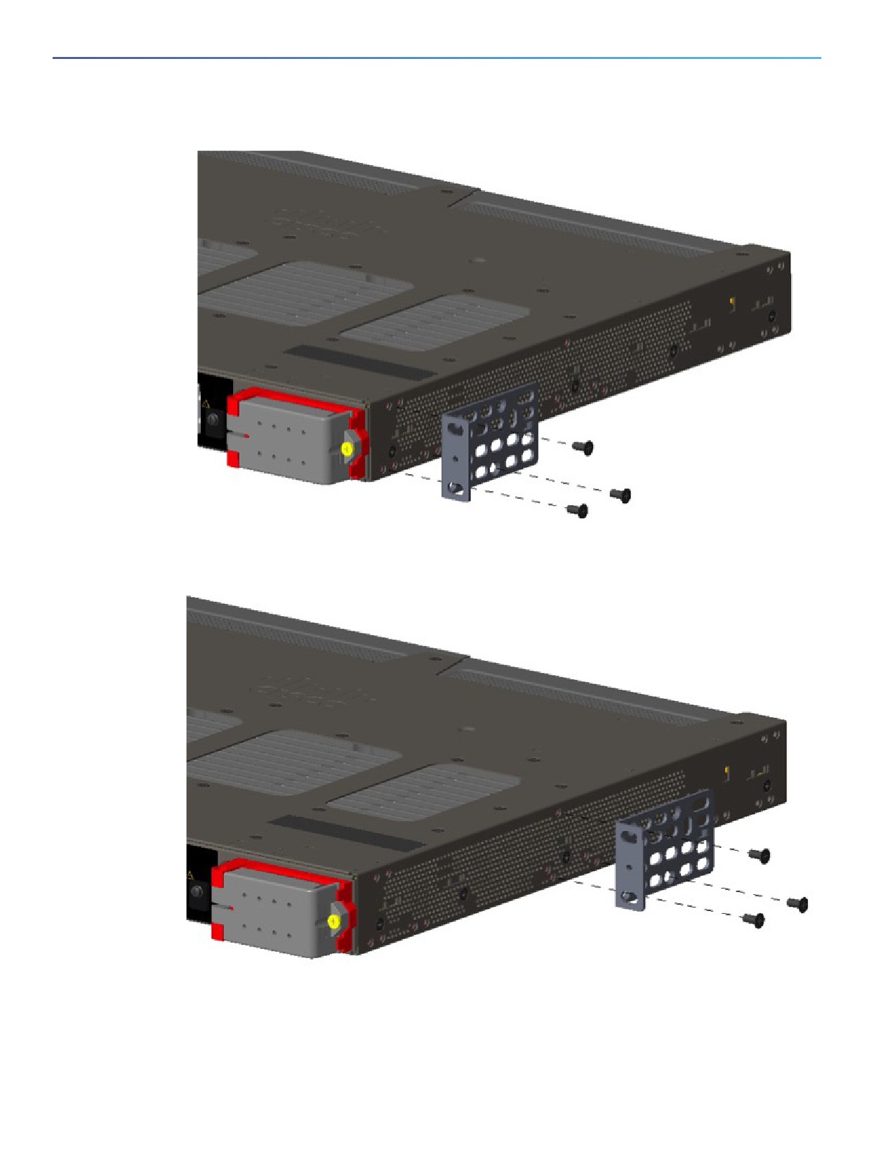
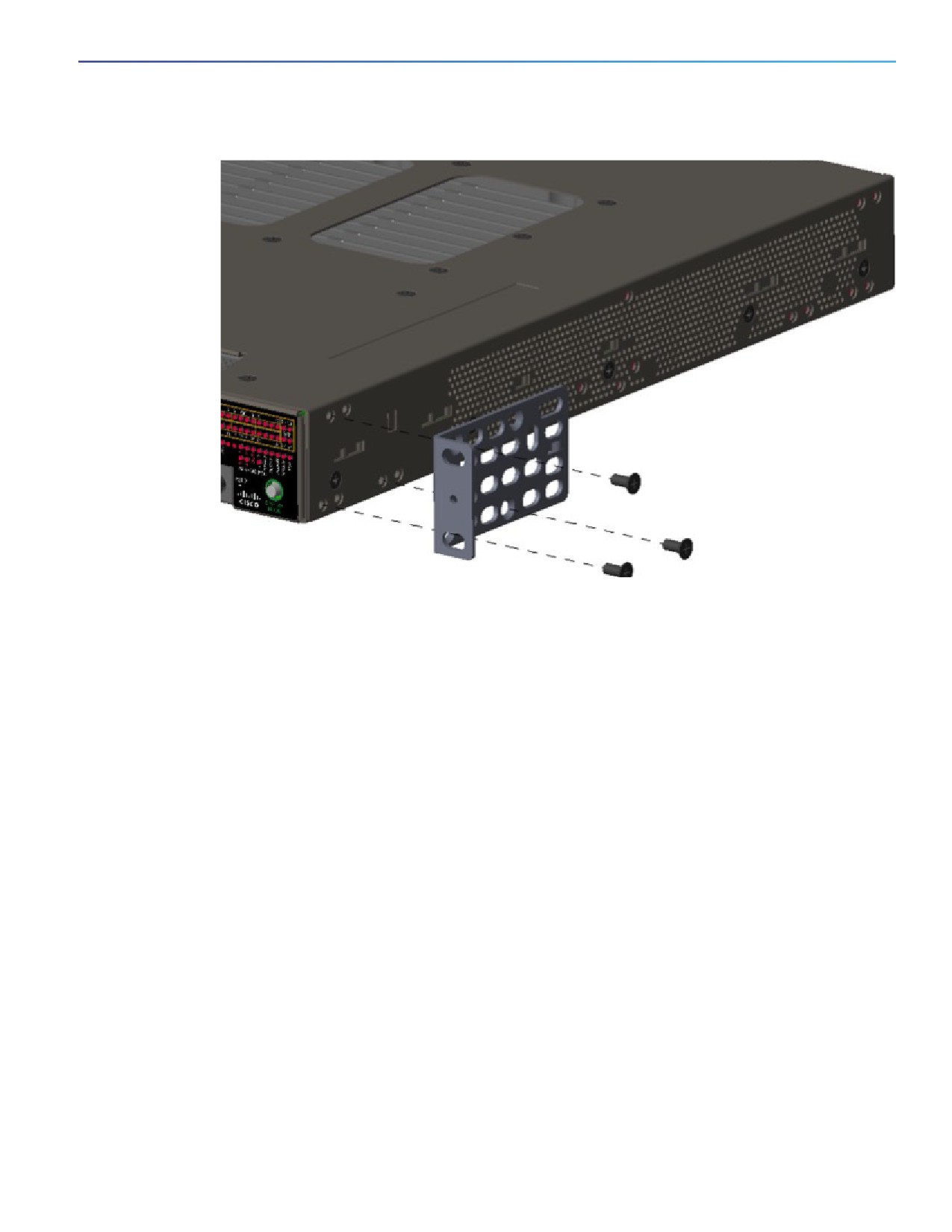
Attaching Brackets for 19-Inch Racks
The following illustrations show how to attach brackets to the switches.
15
Switch Installation
Installing the Switch
Figure 7
Attaching Brackets for 19-Inch Racks (Front bracket)
Figure 8
Attaching Brackets for 19-Inch Racks (Mid Mount)
16
Switch Installation
Installing the Switch
Figure 9
Attaching Brackets for 19-Inch Racks (Rear Mount)
Attaching Brackets for 19-Inch Racks for IP-30 Compliance (Optional)
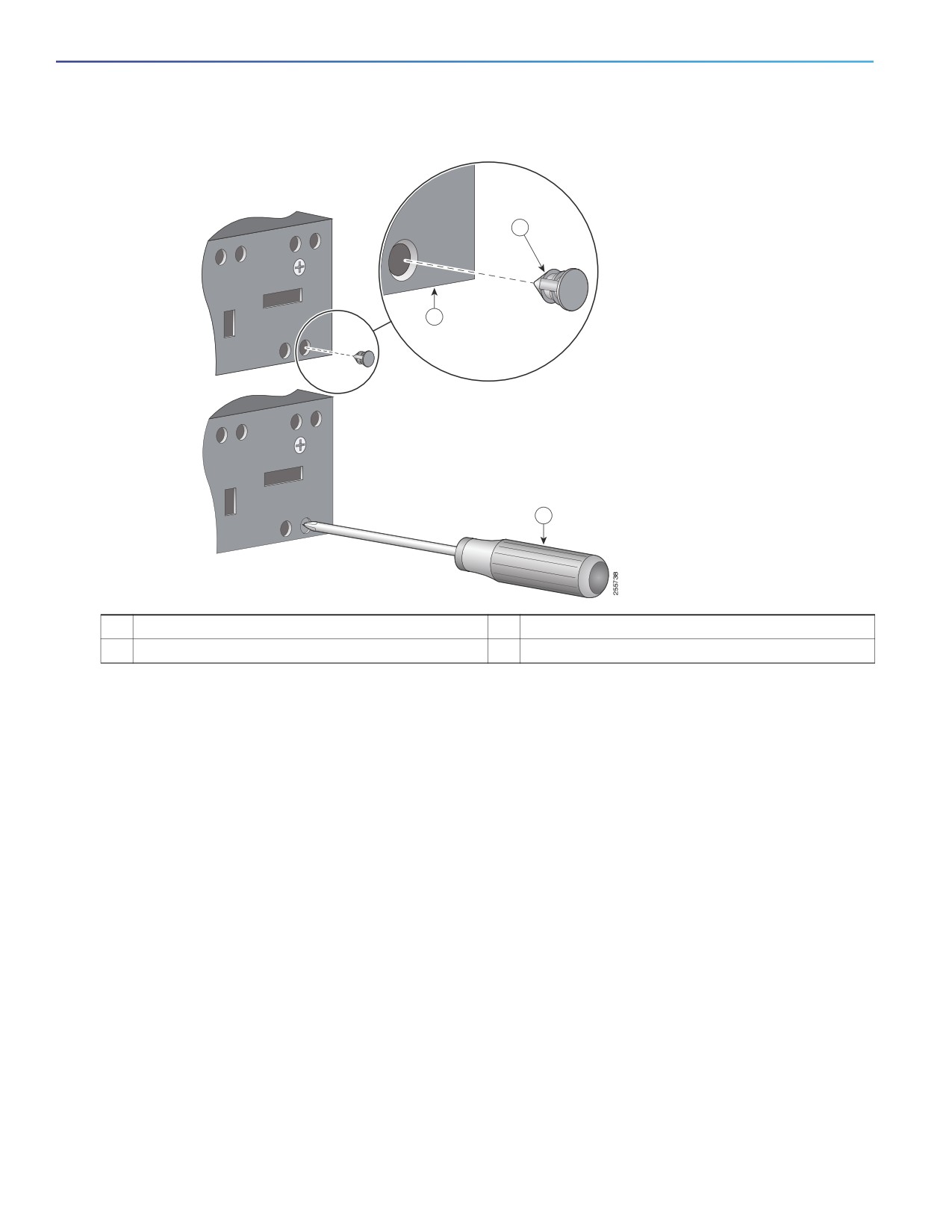
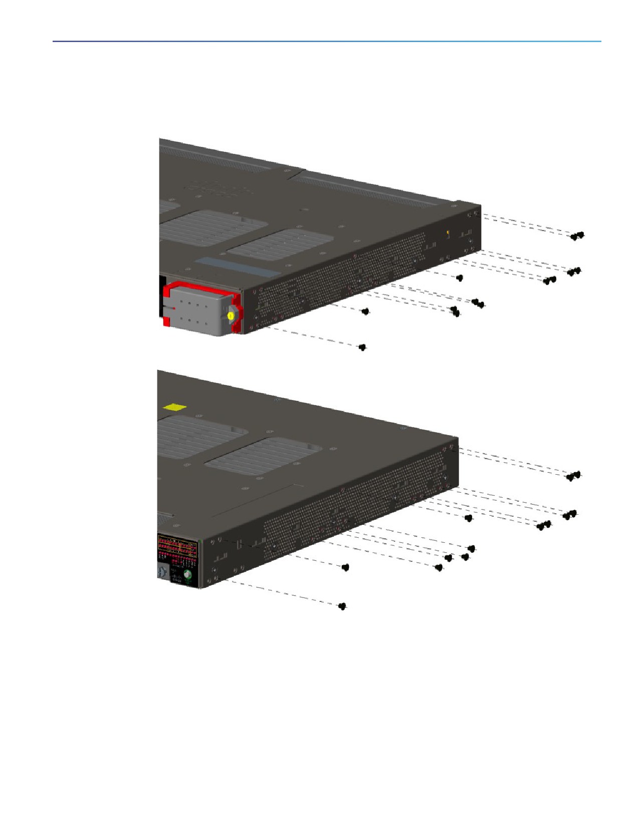
Before installing the mounting brackets, you need to install the rubber plugs in the unused mounting holes. Figure 10 on
page 18 shows a close-up of the rubber plug. You can install the rubber plugs in the holes as shown in Figure 11 on
page 19.
17
Switch Installation
Installing the Switch
Figure 10
Inserting the Rubber Plug
1
2
3
1
Rubber plug
3
Screwdriver
2
Switch
1. Identify your bracket mounting position. See Attaching Brackets for 19-Inch Racks, page 15.
2. Insert the rubber plugs in the appropriate holes on both sides of the switch. See Figure 11 on page 19.
3. Use a screwdriver or pen to completely push in the rubber plugs. See Figure 10 on page 18.
4. Install the brackets on both sides of the switch. See Attaching Brackets for 19-Inch Racks, page 15 and Attaching
Brackets for 19-Inch Racks for IP-30 Compliance (Optional), page 17.
18
Switch Installation
Installing the Switch
Figure 11
Plug locations by position
Note: For IP-30 compliance: If you use 23-inch brackets or ETSI brackets, you can insert the rubber plugs in the same
holes as shown in Figure 11 on page 19 before installing the brackets.
19
Switch Installation
Installing the Switch
Attaching Brackets for 23-Inch Racks
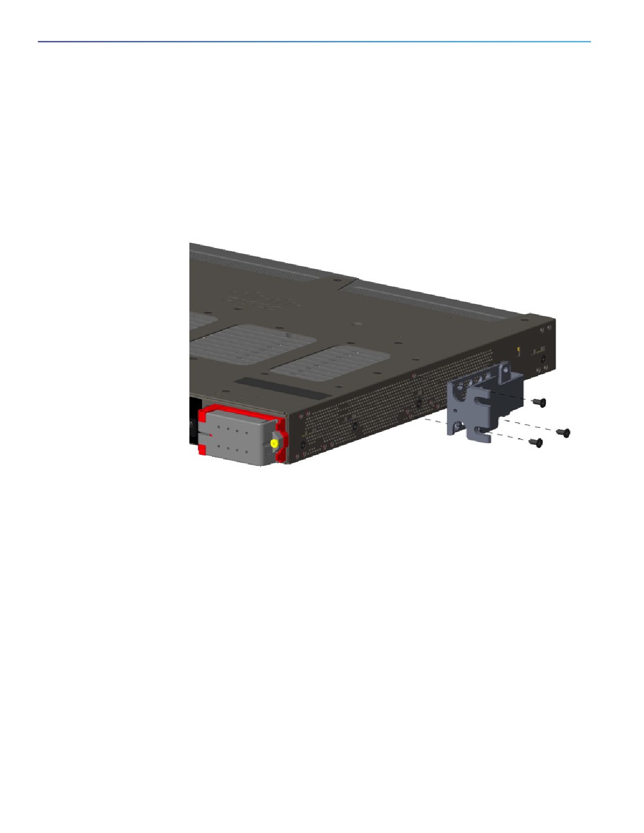
If 23-inch brackets (RM-RGD-23IN=) are required, follow steps in Figure 12 on page 20 for installation.
Note: 23-inch and ETSI brackets should not be used in high vibration environments, including any railway application
(EN50155).
Note: For IP-30 compliance: If you use 23-inch brackets or ETSI brackets, you can insert the rubber plugs in the same
holes as shown in Figure 11 on page 19 before installing the brackets.
Figure 12
Attaching 23-Inch Brackets
Note: For IP-30 compliance: If you use 23-inch brackets, you can insert the rubber plugs in the same holes as shown in
Figure 11 on page 19 before installing the brackets.
20
Switch Installation
Installing the Switch
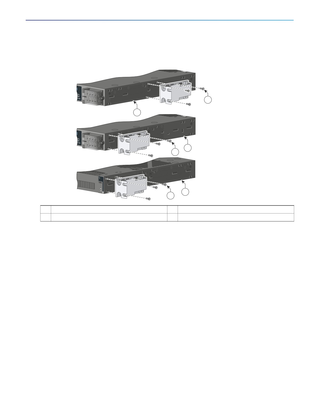
Attaching Brackets for ETSI Racks
Figure 13
Attaching Brackets (RM-RGD-ETSI=) for ETSI Racks
1
2
2
1
3
1
1
Phillips flat-head screws
3
Power-supply-side mounting position
2
Cable-side-mounting position
Note: 23-inch and ETSI brackets should not be used in high vibration environments, including any railway application
(EN50155).
Note: For IP-30 compliance: If you use ETSI brackets, you can insert the rubber plugs in the same holes as shown in
Figure 11 on page 19 before installing the brackets.
Rack-Mounting the Switch
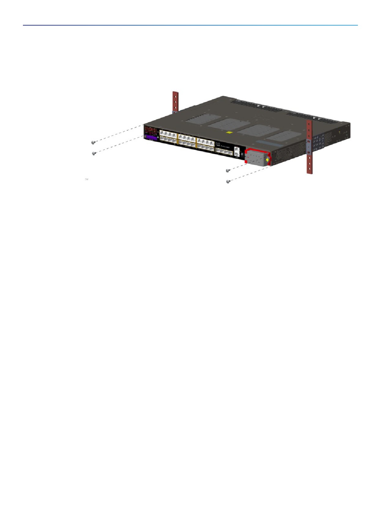
After you attach the brackets on the switch, attach the brackets to the rack. See Figure 14 on page 22.
21
Switch Installation
Installing the Switch
Figure 14
Rack-Mounting
After the switch is mounted in the rack:
1. Wire the switch to a power source. See Wiring the Power Source, page 39.
2. Connect the ports. See Connecting Devices to the Ethernet Ports, page 31.
3. Attach the cable guide to prevent the cables from obscuring the LED panels on the devices in the rack. Use the
supplied black screw to attach the cable guide to the left or right bracket.
For configuration instructions about the CLI setup program, go to Configuring the Switch with the CLI Setup Program,
page 57.
Wall-Mounting
To wall-mount the switch, follow the steps in these sections:
Attaching Brackets, page 23
Attaching Brackets for IP-30 Compliance (Optional), page 24
Wall-Mounting the Switch, page 24
Warning: Read the wall-mounting instructions carefully before beginning installation. Failure to use the correct
hardware or to follow the correct procedures could result in a hazardous situation to people and damage to the
system. Statement 378
Warning: For mounting railway-application equipment and for EN50155 standard compliance, the switch must be
installed only in a rack mid-mounting position. If you install the switch in a front rack-mounting (cable side or power
supply side) position or in a wall-mounting position, a mechanical failure can occur that results in the switch
becoming detached from the rack. Statement 403
If the switch is wall-mounted in an enclosure, follow these minimum clearances:
Sides of switch (facing up and facing down): 3.75 in. (9.52 cm)
Port side 3.0 in. (7.62 cm)
Power supply side: 5.25 in. (13.33 cm)
Cover side (not facing wall): 1.75 in. (4.44 cm)
22
Switch Installation
Installing the Switch
Base side (facing wall): 0 in. (0 cm)
Attaching Brackets
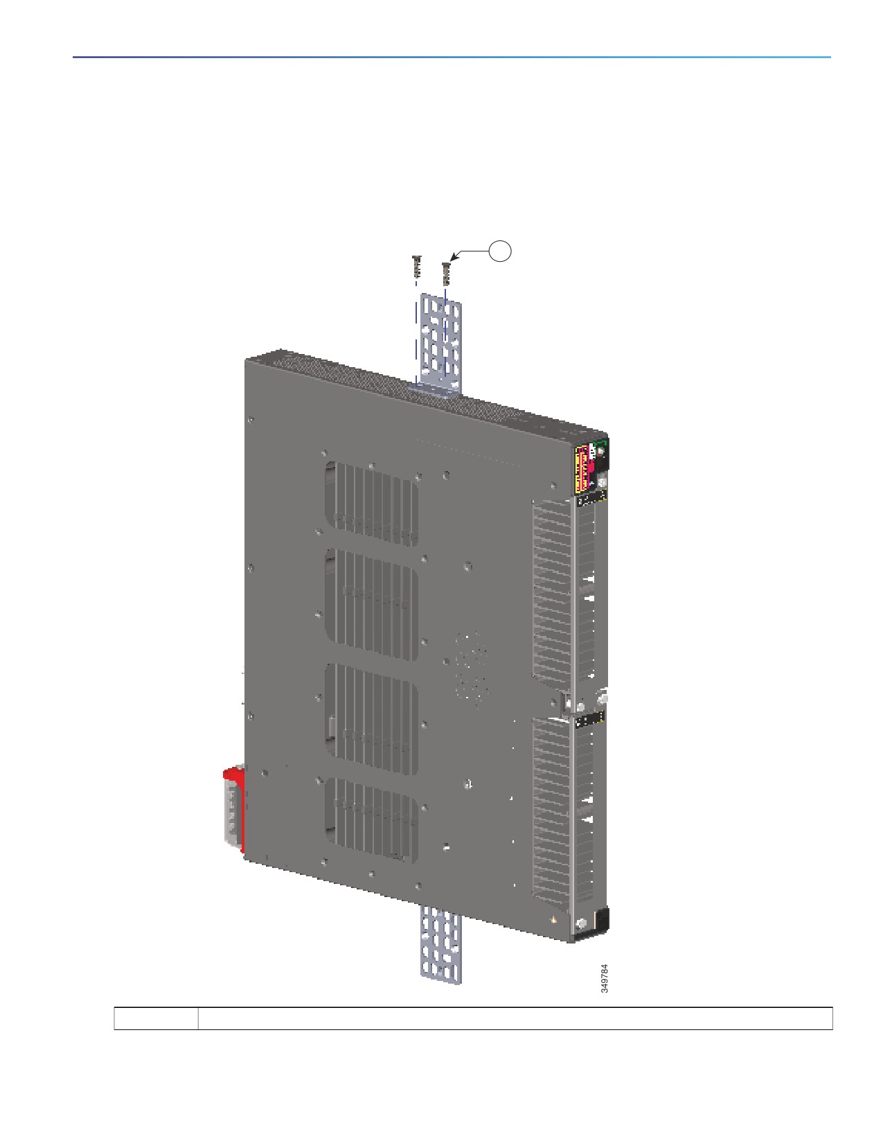
Figure 15
Attaching 19-inch Rack Brackets
1
1
Phillips truss-head screws
23
Switch Installation
Installing the Switch
Attaching Brackets for IP-30 Compliance (Optional)
1. Insert the rubber plugs in the appropriate holes on both sides of the switch. See Figure 10 on page 18.
2. Use a screwdriver or pen to completely push in the rubber plugs. See Figure 10 on page 18.
3. Install the brackets on both sides of the switch. See Attaching Brackets for 19-Inch Racks, page 15.
Wall-Mounting the Switch
For the best support of the switch and cables, ensure that the switch is attached securely to wall studs or to a firmly
attached plywood mounting backboard.
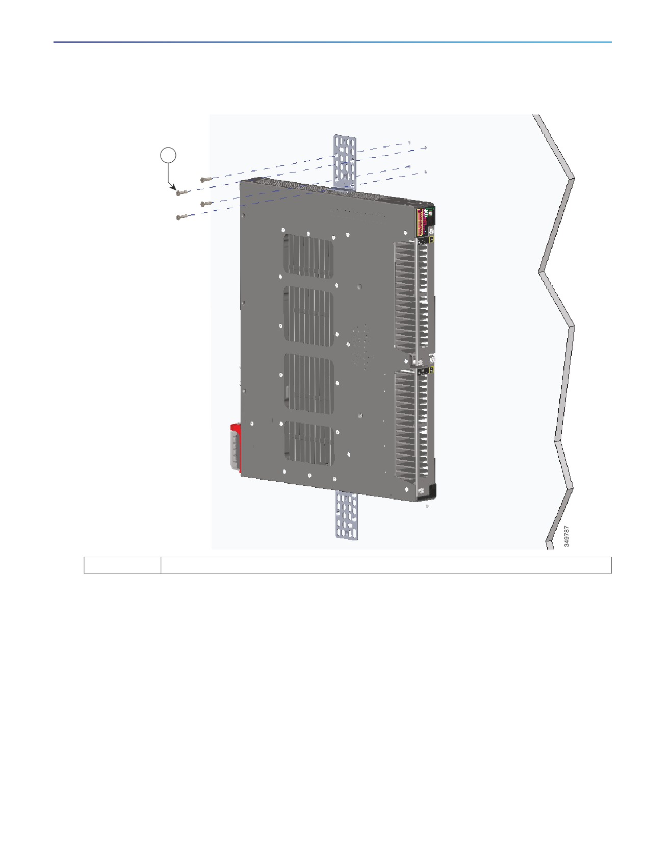
Orientation should exactly match the figure below, with power terminal down, the LEDs up, and the venting and Cisco
Logo facing away from the wall. See Figure 16 on page 25 and After the Switch is Mounted on the Wall, page 25.
24
Switch Installation
Installing the Switch
Figure 16
Wall-Mounting
1
1
User-supplied screws
After the Switch is Mounted on the Wall
Wire the switch to a power source. See Wiring the Power Source, page 39.
For configuration instructions about using the CLI setup program, go to Configuring the Switch with the CLI Setup
Program, page 57.
Connect the switch ports. See the Connecting Devices to the Ethernet Ports, page 31.
25
Switch Installation
Installing and Removing SFP Modules
Installing and Removing SFP Modules
This section presents procedures to install and remove fiber-optic and 1000BASE-T SFP transceiver modules.
Installing SFP Modules
These sections describe how to install and remove SFP modules. SFP modules are inserted into SFP module slots on the
front of the switch. Field-replaceable SFP modules provide the uplink interfaces, send (TX) and receive (RX).
You can use any combination of rugged SFP modules. Each SFP module must be of the same type as the SFP module
on the other end of the cable, and the cable must not exceed the stipulated cable length for reliable communications.
For more information about SFP modules, see Cisco Transceiver Modules.
Caution: Depending on the SFP module you use, the operating temperature limits may be effected. Choose an SFP
module appropriate to the installed environment.
Caution: To prevent electrostatic-discharge (ESD) damage, follow standard board and component handling
procedures.
Warning: Do not insert and remove SFP modules while power is on; an electrical arc can occur. This could cause an
explosion in hazardous location installations. Be sure that power is removed or the area is nonhazardous before
proceeding. Statement 1087
Note: Removing and installing an SFP module can shorten its useful life. Do not remove and insert any module more often
than is absolutely necessary.
Caution: Do not install or remove the LC SFP module with fiber-optic cables attached because of potential damage
to the cables, the cable connector, or the optical interfaces in the SFP module. Disconnect all cables before
removing or installing an SFP module.
Removing and installing an SFP module can shorten its useful life. Do not remove and insert SFP modules more
often than is absolutely necessary.
Installing Fiber Optic SFP Modules
Warning: Class 1 laser product. Statement 1008
To install and cable an optical SFP transceiver uplink port:
1. Attach an ESD-preventive wrist strap to your wrist and to a bare metal surface.
2. Find the send (TX) and receive (RX) markings on the module top.
On some SFP modules, the send and receive (TX and RX) markings might be replaced by arrows that show the direction
of the connection, either send or receive (TX or RX).
3. If the module has a bale-clasp latch, move it to the open, unlocked position.
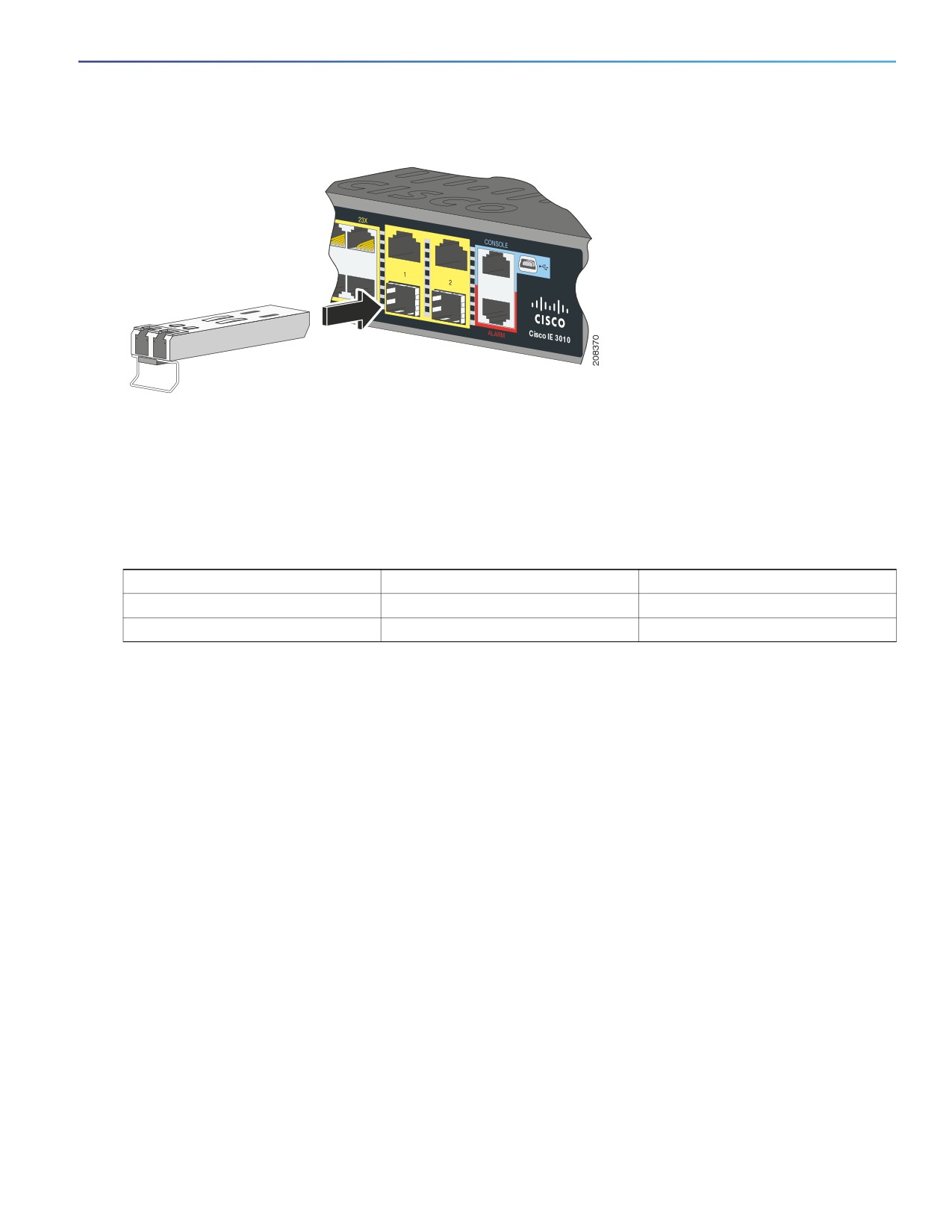
4. Align the module in front of the slot opening, and push until you feel the connector snap into place.
5. If the module has a bale-clasp latch, close it.
6. For fiber-optic SFP modules, remove the dust plugs and save.
7. Connect the SFP cables.
26
Switch Installation
Installing and Removing SFP Modules
Figure 17
Installing an SFP Module
Caution: Do not remove the dust plugs from the fiber-optic SFP module port or the rubber caps from the fiber-optic
cable until you are ready to connect the cable. The plugs and caps protect the SFP module ports and cables from
contamination and ambient light.
Installing 100/1000BASE-T SFP Modules
Table 9
100/1000BASE-T SFP Modules
Model Number
Downlink Support
Uplink Support
GLC-T
10/100/1000
10/100/1000
GLC-TE
10/100/1000
10/100/1000
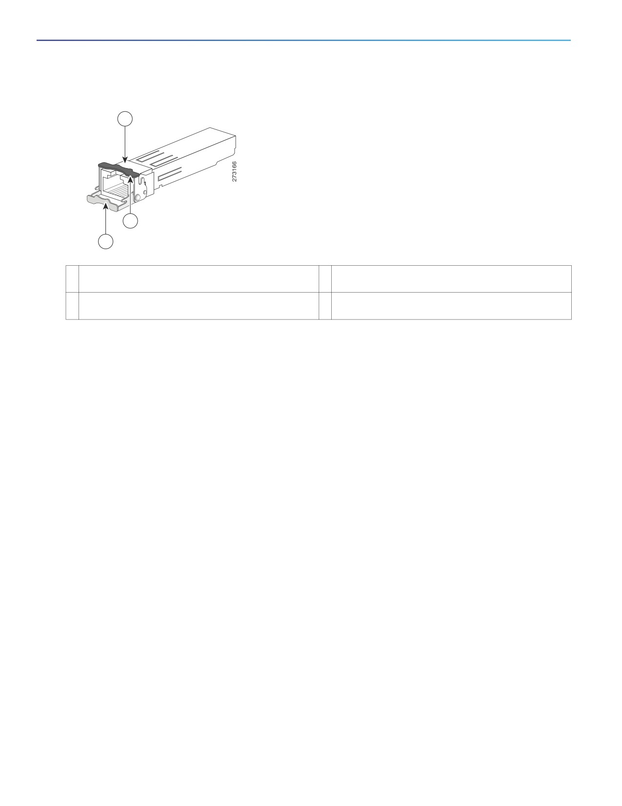
The 100/1000BASE-T (copper) SFP transceiver, see Figure 18 on page 28, has a bale-clasp locking mechanism that
secures the transceiver in the module socket. The SFP network interface is an RJ-45 connector.
27
Switch Installation
Installing and Removing SFP Modules
Figure 18
1000BASE-T SFP Transceiver
1
2
3
1
RJ-45 connector
3
Bale-clasp latching mechanism in the open (unlocked)
position.
2
Bale-clasp latching mechanism in the closed (locked)
position.
Caution: To comply with GR-1089 intrabuilding lightning immunity requirements, you must use grounded, shielded,
twisted-pair, CAT5 cabling.
Note: When connecting to a 100/1000BASE-T-compatible server, workstation, or router, use four twisted-pair,
straight-through CAT5 cabling for the SFP transceiver port. When connecting to a 100/1000BASE-T-compatible switch
or repeater, use four twisted-pair, crossover CAT5 cabling.
To install a 100/1000BASE-T SFP transceiver:
1.
Attach an ESD-preventive wrist strap to your wrist and to the ESD ground connector on the chassis or to a properly
grounded bare metal surface.
Caution: To avoid ESD damage, handle the SFP by its sides; do not touch the connector pins.
2.
Remove the SFP module from its protective packaging.
3.
Check the markings on the SFP transceiver to verify that you have the correct model for your network.
4.
Position the SFP transceiver in front of the port socket opening.
Note: Different Cisco devices have different SFP transceiver socket configurations. Your Cisco device might require
that the SFP transceiver be installed with the bale-clasp either in a latch-up or a latch-down orientation. Verify that
you have the SFP transceiver oriented correctly when you position it in front of the port socket.
5.
With the bale-clasp closed (locked), slide the SFP transceiver into the socket until you feel it snap in place in the
socket. You may hear an audible click as the SFP transceiver latch engages in the socket (Figure 17 on page 27).
6.
Connect the network interface cable RJ-45 plug to the SFP RJ-45 connector.
7.
Observe the port status LED:
— Green indicates that the SFP transceiver and the target device established a link.
— Amber indicates that the port is discovering the network topology and searching for loops. This process takes
about 30 seconds, and then the LED turns green.
— Off indicates that the target device might not be turned on, there might be a cable problem, or there might be
a problem with the adapter installed in the target device. Refer to Troubleshooting, page 45 for solutions to
cabling problems.
28
Switch Installation
Installing and Removing SFP Modules
Connecting to SFP Modules
This section describes how to connect to a fiber-optic or 1000BASE-T SFP port. For instructions on how to install or
remove an SFP module, see Connecting Devices to the Ethernet Ports, page 31.
Warning: Class 1 laser product. Statement 1008
Warning: Do not connect or disconnect cables to the ports while power is applied to the switch or any device on
the network because an electrical arc can occur. This could cause an explosion in hazardous location installations.
Be sure that power is removed from the switch and cannot be accidentally be turned on, or verify that the area is
nonhazardous before proceeding. Statement 1070
Caution: Do not remove the rubber plugs from the SFP module port or the rubber caps from the fiber-optic cable
until you are ready to connect the cable. The plugs and caps protect the SFP module ports and cables from
contamination and ambient light.
Before connecting to the SFP module, be sure that you understand the port and cabling guidelines in Installing and
Removing SFP Modules, page 26. See Cable and Connectors, page 53 for information about the LC on the SFP
module.
Caution: To prevent ESD damage, follow standard board and component handling procedures.
Connecting to a Fiber Optic SFP Module
To connect a fiber-optic cable to an SFP module:
1. Remove the rubber plugs from the module port and fiber-optic cable, and store them for future use.
2. Insert one end of the fiber-optic cable into the SFP module port.
3. Insert the other cable end into a fiber-optic receptacle on a target device.
4. Observe the port status LED:
— The LED turns green when the switch and the target device have an established link.
— The LED turns amber while the STP discovers the network topology and searches for loops. This process takes
about 30 seconds, and then the port LED turns green.
— If the LED is off, the target device might not be turned on, there might be a cable problem, or there might be a
problem with the adapter installed in the target device. See Troubleshooting, page 45 for solutions to cabling
problems.
5. If necessary, reconfigure and restart the switch or the target device.
Connecting to a 1000BASE-T SFP Module
To connect a CAT5 cable to a 1000BASE-T SFP module:
Caution: To prevent ESD damage, follow standard board and component handling procedures.
1. When connecting to servers, workstations, and routers, insert a four twisted-pair, straight-through cable in the
RJ-45 connector. When connecting to switches or repeaters, insert a four twisted-pair, crossover cable.
Note: When connecting to a 1000BASE-T device, use a four twisted-pair CAT5 cable.
29
Switch Installation
Replacing the SD Flash Memory Card
2. Insert the other cable end in an RJ-45 connector on a target device.
3. Observe the port status LED.
— The LED turns green when the switch and the target device have an established link.
— The LED turns amber while the STP discovers the network topology and searches for loops. This process takes
about 30 seconds, and then the port LED turns green.
— If the LED is off, the target device might not be turned on, there might be a cable problem, or there might be
problem with the adapter installed in the target device. See Troubleshooting, page 45 for solutions to cabling
problems.
4. If necessary, reconfigure and restart the switch or target device.
Removing SFP Modules
1. Attach an ESD-preventive wrist strap to your wrist and to a bare metal surface.
2. Disconnect the cable from the SFP module. For reattachment, note which cable connector plug is send (TX) and
which is receive (RX).
3. Insert a dust plug into the optical ports of the SFP module.
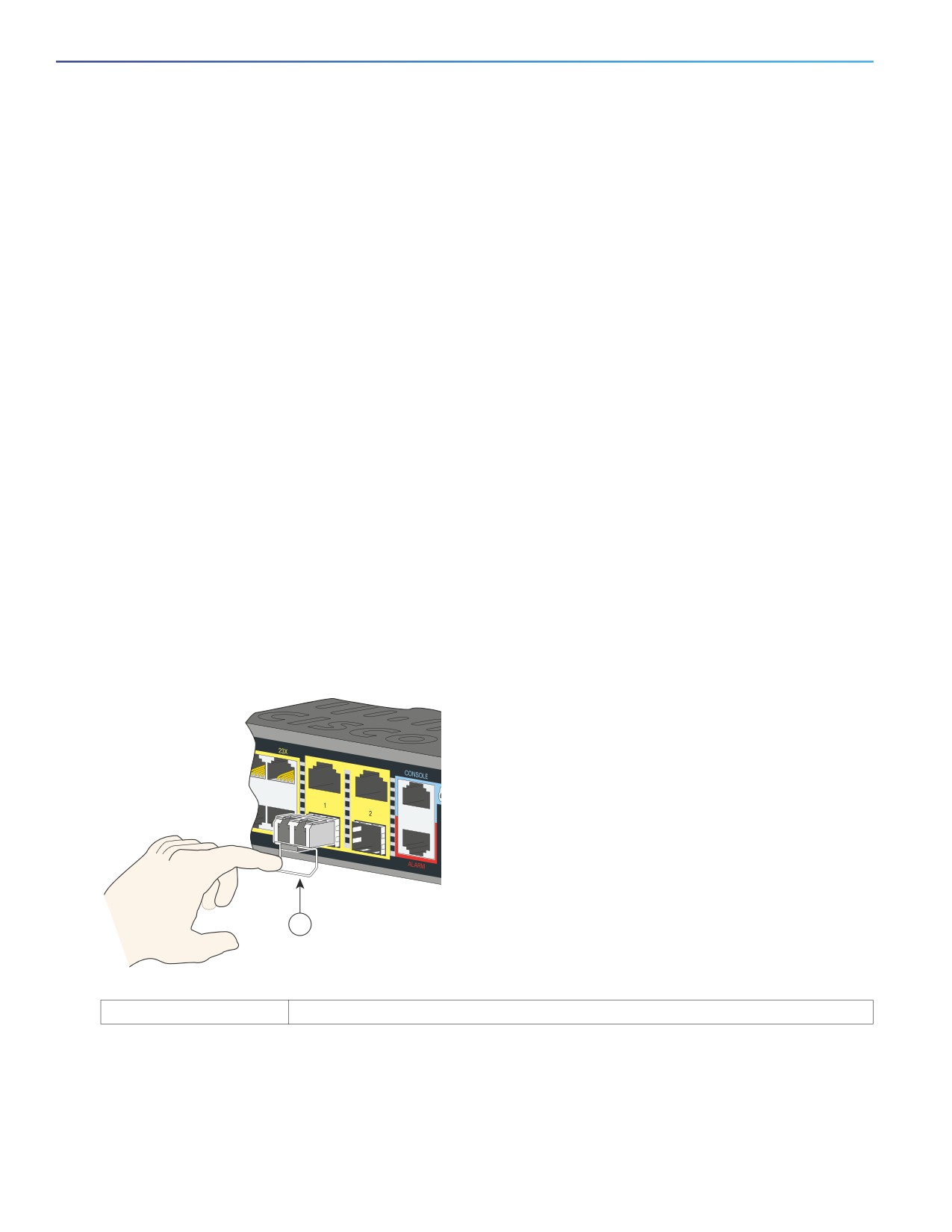
4. If the module has a bale-clasp latch, pull the bale out and down to eject it. If the latch is obstructed and you cannot
use your finger, use a small, flat-blade screwdriver or other long, narrow instrument.
5. Grasp the SFP module, and carefully remove it from the slot.
6. Place the module in an antistatic bag or other protective environment.
Figure 19
Removing a Bale-Clasp Latch SFP Module
1
1
Bale clasp
Replacing the SD Flash Memory Card
1. Locate the flash memory card slot on the cable-side of the switch.
2. Loosen the captive thumb screw. (Be careful not to cross-thread or over-tighten the thumb screw.)
30
Switch Installation
Connecting Devices to the Ethernet Ports
3. Pull the cover open, and pull the cover tab from the hinge.
4. Gently push the flash memory card to eject it. Place it in an anti-static bag to protect it from static discharge.
5. Push the replacement card into the slot, and press it firmly in place. The card is keyed so that you cannot insert it
the wrong way.
6. Place the flash card slot cover tabs into the hinge.
7. Close the cover, and hand-tighten the screw.
Connecting Devices to the Ethernet Ports
The Ethernet ports use standard RJ-45 connectors with Ethernet pinouts. The maximum cable length is 328 feet (100
meters). The 100BASE-TX and 1000BASE-T traffic requires Category 5, Category 5e, or Category 6 UTP cable. The
10BASE-T traffic uses Category 3 or Category 4 cable.
The autonegotiation feature is enabled by default on the switch. At this setting, the switch ports configure themselves to
operate at the speed of the attached device. If the device does not support autonegotiation, you can set the switch port
speed and duplex parameters. To maximize performance, either let the ports autonegotiate both speed and duplex, or
set the port speed and duplex parameters on both ends of the connection.
For simplified cabling, the automatic medium-dependent interface crossover (auto-MDIX) feature is enabled by default.
With auto-MDIX enabled, the switch detects the required cable type for copper Ethernet connections and configures the
interface accordingly. Therefore, you can use either a crossover or a straight-through cable for connections to a Ethernet
port, regardless of the type of connected device.
See the switch software configuration guide or the switch command reference on Cisco.com for more information about
autonegotiation and auto-MDIX.
If auto-MDIX is disabled, use the guidelines in Cables and Adapters, page 55 to select the cable for connecting the
Ethernet ports to other devices.
When using PoE/PoE+, those ports have the same autonegotiation settings and cabling requirements as those in the
Connecting Devices to the Ethernet Ports, page 31. These ports provide PoE power.
See Cable and Connectors, page 53 for information on the cables and connectors.
The ports provide PoE/PoE+ support for devices compliant with IEEE 802.3af/at and also provide Cisco prestandard
PoE/PoE+ support for Cisco IP Phones and Cisco Aironet Access Points.
On a per-port basis, you can control whether or not a port automatically provides power to a connected IP phone or an
access point.
To access an advanced PoE planning tool, use the Cisco Power Calculator on Cisco.com:
You can use this application to calculate the power supply requirements for a specific PoE/PoE+ configuration. The
results show output current, output power, and heat dissipation.
Warning: Voltages that present a shock hazard may exist on Power over Ethernet (PoE) circuits if interconnections
are made using uninsulated exposed metal contacts, conductors, or terminals. Avoid using such interconnection
methods, unless the exposed metal parts are located within a restricted access location and users and service
people who are authorized within the restricted access location are made aware of the hazard. A restricted access
area can be accessed only through the use of a special tool, lock and key or other means of security. Statement
1072
31
Switch Installation
Where to Go Next
Caution: Category 5e and Category 6 cables can store high levels of static electricity. Always ground the cables to
a suitable and safe earth ground before connecting them to the switch or other devices.
Where to Go Next
You can use the default configuration or use any of the management options described in the Management Options,
page 12 to change the switch settings.
32
Power Supply Installation
This chapter describes how to remove and install a new or replacement power supply. Your switch ships with at least
one installed power-supply module (AC or DC, depending on your order).
The power-supply modules are field-replaceable units (FRUs) and are hot-swappable when deployed in non-hazardous
locations.
For translations of the safety warnings in this chapter, see the Regulatory Compliance and Safety Information for the
Cisco IE 4010 Switch on Cisco.com.
Power-Supply Modules, page 34
Installation Guidelines, page 35
Grounding the Switch, page 36
Installing the Power-Supply Module in the Switch, page 37
Wiring the Power Source, page 39
Removing the Power-Supply Module, page 44
33
Power Supply Installation
Power-Supply Modules
Power-Supply Modules
Table 10
Power Supply Modules
Model
Description
PWR-RGD-LOW-DC-H
Low-voltage DC. For detailed specifications, see the IE 4010 Data Sheet.
PWR-RGD-AC-DC-H
High-voltage AC or DC. For detailed specifications, see the IE 4010 Data Sheet.
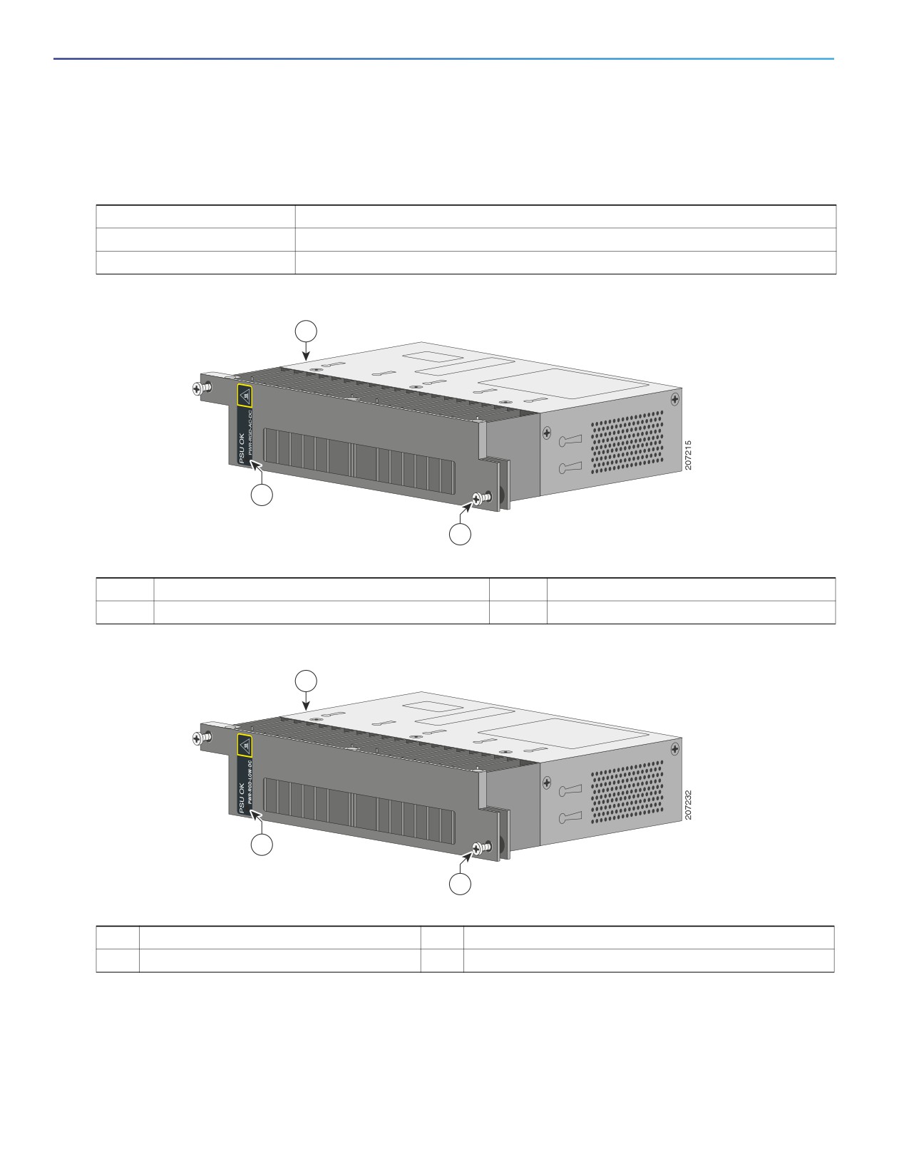
Figure 20
PWR-RGD-AC-DC-H Power-Supply Module
1
2
3
1
Power-supply module
3
Captive screw
2
PSU OK LED
Figure 21
PWR-RGD-LOW-DC-H Power-Supply Module
1
2
3
1
Power-supply module
3
Captive screw
2
PSU OK LED
Note: Power Supplies with the -H suffix are required for hazardous environment installations. Non hazardous
environments may use either -H or non -H supplies.
For a description of the PSU OK LEDs, see the Power-Supply Module LEDs, page 8.
34
///////////////////////////////////////