Remote HMI V6 Industrial-Grade Thin-Client Firmware. Manual (Firmware Version: 6.00.00) - page 2
Remote HMI
Manual
11. Click on Apply to set up the connection.
9 The connection is shown in the address book.
5.2.2
Set-up of the VNC connection.
The VNC software must be installed on the Thin Client and the server, requiring
Administrator authority on both.
To set up the connection you require the IP address of the VNC server and,
depending on the configuration, the VNC password.
If the port number of the VNC server is different from the standard port, the IP address
needs to be extended to include the port number, for example: 192.168.1.23:5901
1. Open the Address Book register.
2. Click on
+Add .
¾ A new address book entry is created.
3. Click on Edit .
4. In the Connection Settings, select "VNC" from the Type drop-down field.
5. Under Name, enter the name of the connection.
6. Under Server Address, enter the IP address of the server.
To ensure automatic access to the connected server you have to enter the correct
logon data.
7. Enter the logon data of the server.
8. If you want to be able to call up the remote connection via the keyboard, use
Hotkey to specify a hotkey.
9. Under Show on, select the display option.
10. Specify the minimum user role required for the manual set-up of the connection.
If a user does not have the required authority to set up the connection, this connection
is greyed out in the address book.
11. Click on Apply to set up the connection.
9 The connection is shown in the address book.
5.2.3
Preparation of host for VNC connection
The process varies according to which VNC service is used. For more information,
please refer to the documentation provided by the VNC service manufacturer.
This process requires Administrator authority.
1. Make sure that the Thin Client can contact the host. If both are part of the same
network, this will be the case.
2. Make sure the VNC service is installed and activated on the host (see Activating
VNC server system on the host).
3. If the network connection is protected via a firewall you need to configure this
firewall. Permit network communication via the port where the VNC service is
ready to receive (5900 as a standard).
4. If the network connection is protected via a router, you need to configure this
router. For the transfer of network communication, specify every configured port
where the VNC service is ready to receive (5900 as a standard).
5. Check whether the VNC service is working properly and whether it accepts
incoming connections.
9 The host is ready.
38
Remote HMI
Manual
5.2.4
Preparation of Thin Client for the VNC connection
The process varies according to which VNC service is used. For more information,
please refer to the documentation provided by the VNC service manufacturer.
This process requires Administrator authority.
1. Make sure that the Thin Client can contact the host. If both are part of the same
network, this will be the case.
2. If the VNC connection of the Thin Client is protected via a proxy server you have
to specify the proxy server in the VNC viewer.
9 The Thin Client is ready
5.3
Test of remote connection
Remote connection does not start
¾ If no connection has been established, the symbol changes to . The
system will issue an error message.
• Check whether the settings are correct.
If the host is available, try to narrow down the source of the problem with the following
checks:
Check RDP connection
1. Check in the server's system settings whether a RDP connection is permitted.
2. Check whether the Thin Client is listed at the server as a user with the required
user rights.
Check VNC connection
1. Check whether the VNC service is configured correctly.
2. Check whether the port number has been entered correctly.
Check KVM-over-IP connection
1. Check the configuration of the KVM box.
2. Check whether the port number has been entered correctly.
5.4
Managing remote connections
Navigation elements
opens an item in the list
closes an item in the list
In order to be able to edit the settings, the connection must be inactive.
Moving connections in the list
1. Open the entry in the Address Book register with .
2. Click on ↑ to move the entry up one place in the list.
3. Click on ↓ to move the entry down one place in the list.
9 The connection is moved in the list.
Editing connection settings
1. Deactivate the connection in the Address Book register.
2. Open the entry.
3. Click on Edit to edit the settings.
39
Remote HMI
Manual
4. Change the settings as required.
5. Click on Apply to accept the changes.
Click on Revert to reject the changes.
6. Click on Manage to edit the list.
Click on [
] to close the entry and return to the list.
Deleting a connection
1. Deactivate the connection in the Address Book register.
2. Open the connection.
3. Click on Delete to delete the connection.
4. Confirm the security message.
9 The connection is deleted.
Copying a connection
1. Deactivate the connection in the Address Book.
2. Open the entry.
3. Click on Copy to copy the settings.
¾ A new entry is created.
4. Open the entry and edit the settings as required.
5. Click on Apply to accept the changes.
Click on Revert to reject the changes.
6. Click on Manage to edit the list.
Click on [
] to close the entry and return to the list.
40
Remote HMI
Manual
6
App management
Requires a Pro licence.
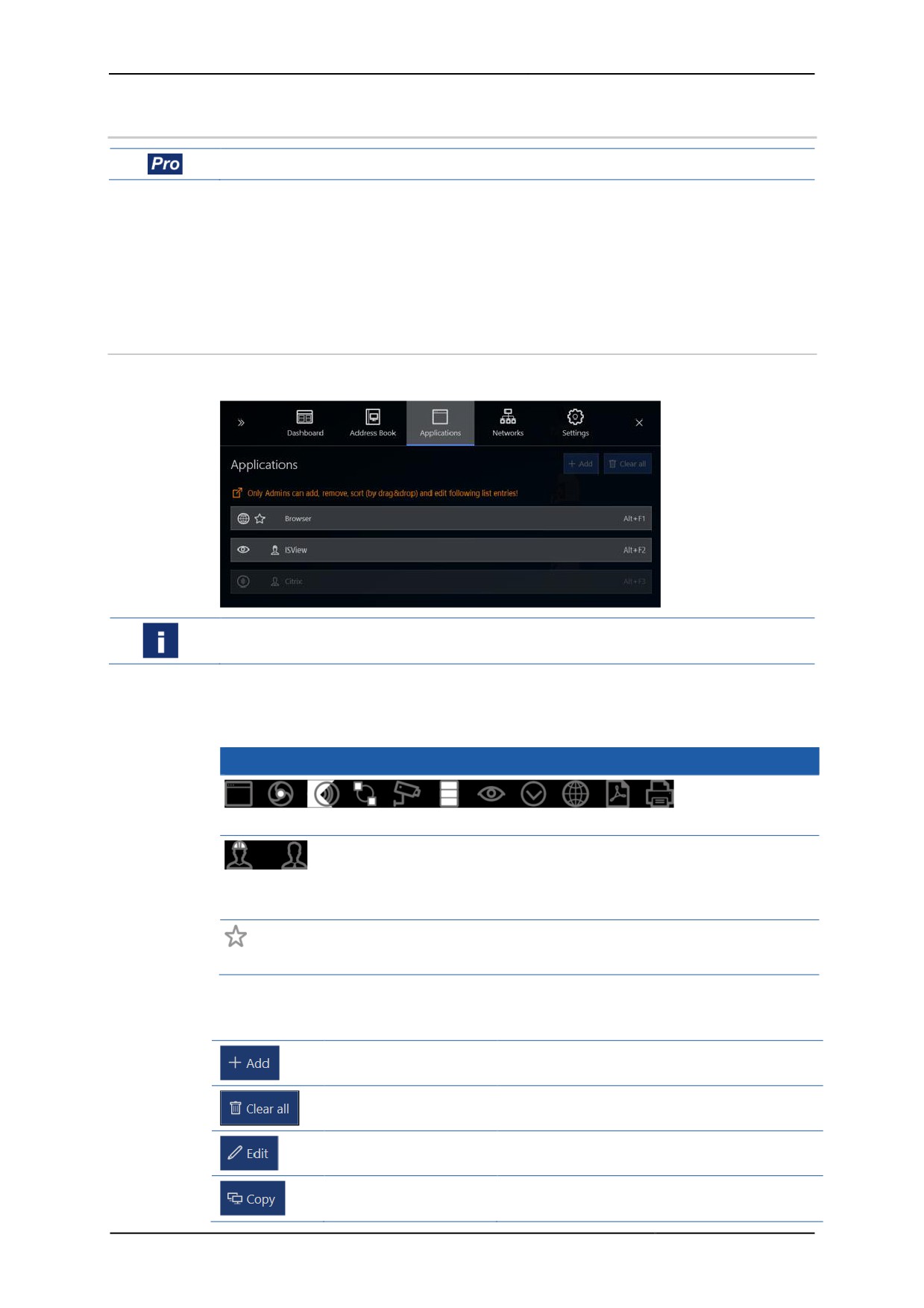
Use the Applications register to add and manage links to Windows tools and
applications, virus protection software or EXE applications such as the Citrix Receiver.
You can configure the display and behaviour of an app with various settings, and
manage access via the user roles.
Before you can add an app you need to install it on the Thin Client. The Thin Client
has to meet the system requirements of the app.
6.1
Options in the Applications register
The Applications register lists all available apps.
If a user does not have the required authority to use the app, this app is greyed out in
the list.
Symbols in the list of apps
You can freely chose the icons representing the apps in the list. In the interest of user-
friendliness we recommend you use commonly used symbols.
Symbols
A selection of icons standing for different types of app.
Engineer, Admin: Defines who is authorised to start the app.
If no symbol is shown all user roles are authorised to start the app.
default, will be connected automatically during start-up
Functions in the Applications register
The available edit functions or buttons depend on the sub-menu.
Add
Adds a new entry.
Clear all
Deletes all entries in the list
Edit
Opens the highlighted entry for editing
Copies the highlighted entry and opens the
Copy
copy for editing
41
Remote HMI
Manual
Delete
Deletes the highlighted entry
Manage
Navigates back to the list level
Apply
Applies input
Revert
Rejects input
Moves the highlighted entry one place up in
Up
the list
Moves the highlighted entry one place down
Down
in the list
Forces the shut-down of an open application
Terminate
with possible loss of data
Opens the selection window for executable
Select file
files
Navigation elements
opens an item in the list
closes an item in the list
Hotkey for starting applications
An application can be selected via the keyboard if a hotkey has been created under
the Hotkey menu item. Three keys can be specified.
First key
Second key
Third key
[Shift]
[Ctrl]
none
[Ctrl]
[Alt]
[F1] ... [F12]
The Ctrl key must not be selected twice.
Each hotkey can only be allocated once.
Command line parameters
You can define a command line parameter for each app that allocate application-
specific parameters.
Example:
www.stahl.de in the kiosk mode.
Please refer to the description of each application for information on permitted
command line parameters.
42
Remote HMI
Manual
Application privilege level
Level
Meaning
Run as standard user
Starts the application with standard user authority
Run as administrator user
Starts the application with Administrator authority
You can define name and password for the Admin
account in the System & Proxy menu.
Run elevated
Starts the application with extended Administrator
authority
You can define name and password for the Admin
account in the System & Proxy menu.
6.2
Adding apps
Requires a Pro licence.
Compatibility with third-party software
The firmware is qualified for software that is included in the delivery of the supported
HMI devices. R. STAHL HMI Systems GmbH does not accept any liability for the
functionality of the software of any other providers. Before installing software of other
providers make sure it is compatible.
Checking system requirements and ability to run of the application
1. Make sure that the application is compatible.
2. Check whether the system requirements are met.
3. Check whether the application can be installed on the Thin Client. This is done in
the Admin role.
4. Check whether the application works smoothly.
9 If all conditions have been met, the application is compatible and able to run.
Adding an app
1. Open the Applications.
2. Click on
+Add .
¾ A new entry is created.
3. Open the entry.
4. Under Icon, select a suitable symbol from the drop-down field.
5. Activate Autostart if you want the application to start automatically.
6. Under Name, enter the name of the application.
7. If you want to be able to call up the remote connection via the keyboard, use
Hotkey to specify a hotkey.
8. Enter the file path in the Path field or use the Select File button to open the
Windows Explorer to find the program. Select the program file and confirm the
dialogue by clicking on Open .
9. If you want to define application-specific parameters, click on Parameters to
enter a command line parameter. For information on possible parameters please
refer to the manual of the application.
10. Click on Application privilege level to specify how the application should be
started.
11. Activate Close RemoteHMI menu on app start if you wish to close the
firmware when starting the application.
43
Remote HMI
Manual
If the application requires Administrator or extended authority, you can store the login
data for the Administrator account under Use predefined admin login
credentials. You then no longer need to enter the login data when starting the app.
12. Activate Use predefined admin login credentials if you want to start the
application via the login data of the Thin Client. Enter the user name and the
password.
13. Click on Min user role required to start app manually to define the
lowest required user authority level for starting the application.
If the user is not authorised to start the application manually, it will be greyed out in the
Applications register.
14. Click on Apply to accept the input.
¾ The application will be displayed on the dashboard and in the Applications
register.
15. Click on Manage to move the app in the list.
Click on [
] to close the entry and return to the list.
16. Check whether the app opens correctly when clicking on the entry.
6.3
Managing apps
Navigation elements
opens an item in the list
closes an item in the list
Moving an application in the list
1. In the Applications register, open the entry you want by clicking on
2. Click on ↑ to move the entry up one place in the list.
3. Click on ↓ to move the entry down one place in the list.
Changing application settings
1. Open the entry you want in the Applications register.
2. Click on Edit to edit the settings.
3. Make the required changes.
4. Click on Apply to accept the changes.
Click on Revert to reject the changes.
5. Click on Manage to edit the list.
Copying an application
1. Check the compatibility and ability to run of the application before creating a link to
a new application (see "Adding apps")
2. Open the Applications register.
3. Open the entry you want to copy.
4. Click on Copy to copy the application's settings.
¾ A new entry is created.
5. Click on Select File and select the program in Windows Explorer.
6. Open the entry and change its settings as described under Adding apps.
7. Click on Apply to apply the changes.
Click on Revert to reject the changes.
8. Click on Manage to move the app in the list.
Click on [
] to close the entry and return to the list.
44

Remote HMI
Manual
Closing an application
In general, you should shut down applications properly to prevent any data loss. If you
cannot shut down an application in the normal way you can force its termination.
1. Open the entry you want in the Applications register.
2. Click on Terminate to force the termination of the application.
3. Confirm the security message.
9 The application is shut down.
Deleting the link to the application
The Delete button only deletes the link to the application and does not de-install the
application.
You can only de-install the program in the Windows user interface.
1. Open the entry you want in the Applications register.
2. Click on Delete to delete the link.
3. Confirm the security message.
9 The link to the app is deleted.
45
Remote HMI
Manual
7
Network
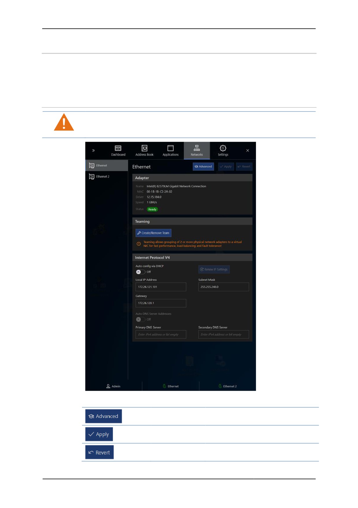
Use the Networks register to configure the Thin Client for incorporation in the
network.
The number and designation of available Ethernet adapters depend on the Thin
Client's hardware.
7.1
Options in the Networks register
Settings on the Windows network level can have an impact on the entire network.
Only click on the Advanced if you know your way around Windows network settings.
If not, ask your network administrator for help.
Buttons in the Networks register
Advanced
Opens the Windows network settings
functions
Apply
Applies input
Revert
Rejects input
46
Remote HMI
Manual
Create/remove
Opens the teaming function dialogue
team
Renew IP
Requests renewed IP configuration
settings
from the DHCP server
7.2
Adapter information
The Adapter section lists information on the chosen Ethernet adapter.
Name
Name of the Ethernet adapter
MAC
MAC address of the Ethernet adapter
Driver
Version of the adapter driver
Speed
Speed of the Ethernet connection
Status
Status of Ethernet connection
7.3
About DHCP
Dynamic Host Configuration Protocol - DHCP
Address allocation with DHCP works according to the client-server principle. The client
requests the IP address configuration from a DHCP server which looks up the
requested data in its database.
The DHCP server can allocate the following settings to the Thin Client:
• IP address
• Sub-net mask
• Standard gateway
• DNS server address
Auto config via DHCP
In the case of automatic allocation, the client sends its address request to all network
participants. The DHCP server responds with a data package that contains, in addition
to a possible free IP address and the client's MAC address, the sub-net mask and the
IP address and ID of the server. The client takes the required data from the response
and informs the DHCP server. The server confirms the TCP/IP parameters and sends
additional information such as the DNS server back to the client. The DHCP server
stores the automatically allocated address together with the MAC address in the
database. This allocation is permanent.
Related topics:
• Set-up of the network adapter
7.4
About DNS
Domain Name System - DNS
DNS is a service that converts domain names into numeric addresses. The basis of
the DNS is a system of directories which manages the domain name space. When a
new domain is created on the internet for example, a DNS server will store the domain
name and the associated IP address. It will use this database to respond to any
incoming queries concerning the domain name space.
Two DNS servers can be addressed with the firmware.
Auto DNS Server Addresses
Use this function to automatically address a DNS server, for example if the IP address
of the DNS server is not known.
47
Remote HMI
Manual
Related topics:
• Set-up of the network adapter
7.5
Set-up of the network adapter
As a factory setting, the automatic address allocation Auto config via DHCP is
activated.
Automatic set-up of the network address
1. Open the Networks register.
2. Check whether Auto config via DHCP is activated.
3. Click on Apply to start the automatic allocation by the DHCP server.
9 IP address, gateway and subnet mask are configured.
Manual set-up of network address
1. Open the Networks register.
2. Deactivate Auto config via DHCP to set up the address manually.
3. Under Local IP address, enter the IP address of the network adapter.
4. Under Subnet Mask, enter the subnet mask.
5. If you want the Thin Client to access a different network, enter the IP address of
the gateway under Gateway.
6. Click on Apply to accept the changes.
9 IP address, gateway and subnet mask are configured.
Manual configuration of the DNS server
1. Open the Networks register.
2. Under Primary DNS Server, enter the IP address of the first DNS server.
3. Under Secondary DNS Server, enter the IP address of the second DNS
server.
4. Click on Apply to accept the settings.
7.6
Teaming function
The teaming function allows you to
• use the Ethernet adapter in the team as stand-by adapters to create a redundancy
and make the system more fail-safe.
• bundle the speed of the Ethernet adapters in order to increase performance.
The teaming function combines several physical network connections to create one
virtual "Network Interface Controller" (NIC).
This is set up at system level via the "Realtek - Ethernet Diagnostic Utility". Do not
execute this function unless:
• You know about virtual network cards
• Both adapters work smoothly
Creating a team
1. Open the Networks register.
2. Click on
+ Create/Remove Team.
¾ The Teaming window will pop up, listing all necessary steps.
3. Wait until the "Realtek Diagnostic Utility" window opens. This may take up to 30
seconds.
4. Highlight the required "PCle Controller" in the left section.
48
Remote HMI
Manual
5. Select "Teaming" in the central section.
Teaming is an advanced function for the server environment. You can use Teaming to
bundle many physical adapters into one team with functions for load sharing and
increased reliability.
6. Select "Create Team" in the right section.
¾ The "Create Team" window will pop up.
7. Enter a name for the team which will later appear in the list of Ethernet adapters.
You can now activate one of the following functions:
• Fast/Giga EtherChannel
• Link Aggregation / LACP
8. Activate "Fast/Giga EtherChannel" to switch to the second adapter if the first one
fails.
9. Activate "Link Aggregation / LACP", to increase bandwidth by using both adapters
simultaneously.
10. Select the physical network adapters which you want to combine as a team.
11. Confirm the selection with "OK".
¾ The new virtual adapter is shown in the "Realtek Diagnostic Utility" window in
the left section.
12. Highlight the team and check the settings in the right section.
13. Close the "Realtek Diagnostic Utility" window.
14. Return to the firmware and restart the system.
9 The virtual adapter will be shown in the Networks register.
Remove Team
1. Open the Networks register.
2. Click on
+ Create/Remove Team.
¾ The Teaming window will pop up, listing all necessary steps.
3. Wait until the "Realtek Diagnostic Utility" window opens. This may take up to 30
seconds.
4. Highlight the virtual adapter in the left section.
5. Open the context menu and select "Remove".
6. Confirm the warning with "OK".
¾ The virtual adapter is removed.
7. Return to the firmware and restart the system.
9 The virtual adapter is removed from the Networks register.
49
Remote HMI
Manual
8
Settings
The Settings register contains many functions with which the Engineer or Admin can
configure the firmware.
8.1
Options in the Settings register
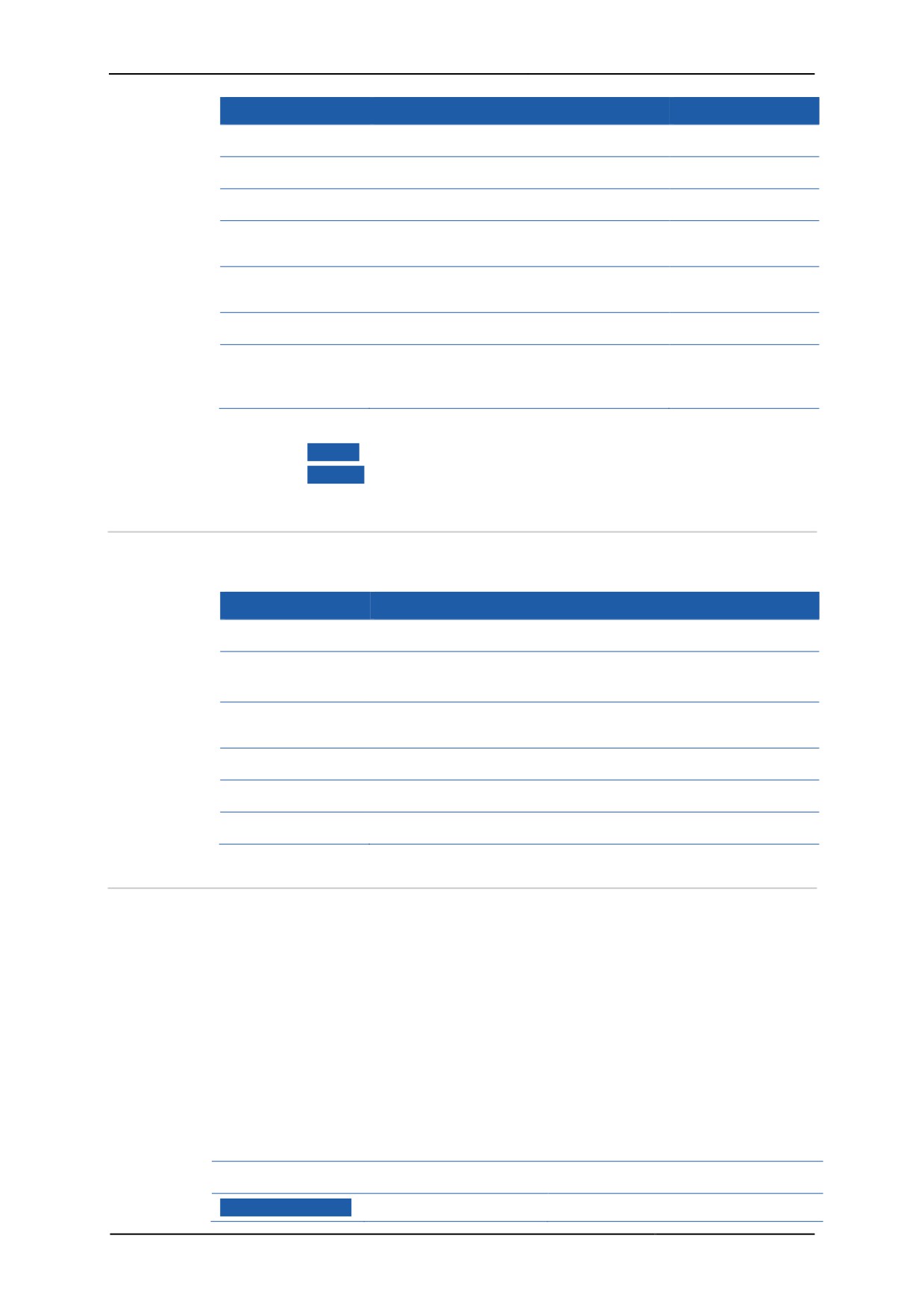
The Settings register contains the following menus:
Menu
Contents
Authorised user
Information
Current system data, settings and
configurations
The menu contents vary depending on the
device platform.
Maintenance
Functions required for the maintenance of
Admin
the Thin Client. Allows addition of third-
party software and drivers.
Activation of Pro licence and Windows
LTSB
System & Proxy Settings concerning device name (in the
Engineer / Admin
network) and proxy server
Protection
Settings concerning system security
Engineer / Admin
Displays
Settings for up to 6 displays
Engineer / Admin
50
Remote HMI
Manual
Menu
Contents
Authorised user
User Interface Behaviour of RemoteHMI menu
Admin
Access Control Setting up of protected user roles
Admin
Connections
Settings of connection options
Engineer / Admin
Keyboard Wedge Setting up the COM interfaces for external
Engineer / Admin
scanners or readers
Import & Export Functions for the export and import of the
Engineer / Admin
device configuration
Updates
Firmware updates
Admin
Legal Notice
Information on licence terms and
conditions for the software used on the
Thin Client
Accept or reject settings
1. Click on Apply to accept the settings.
2. Click on Revert to reject the changes.
8.2
Display of system information
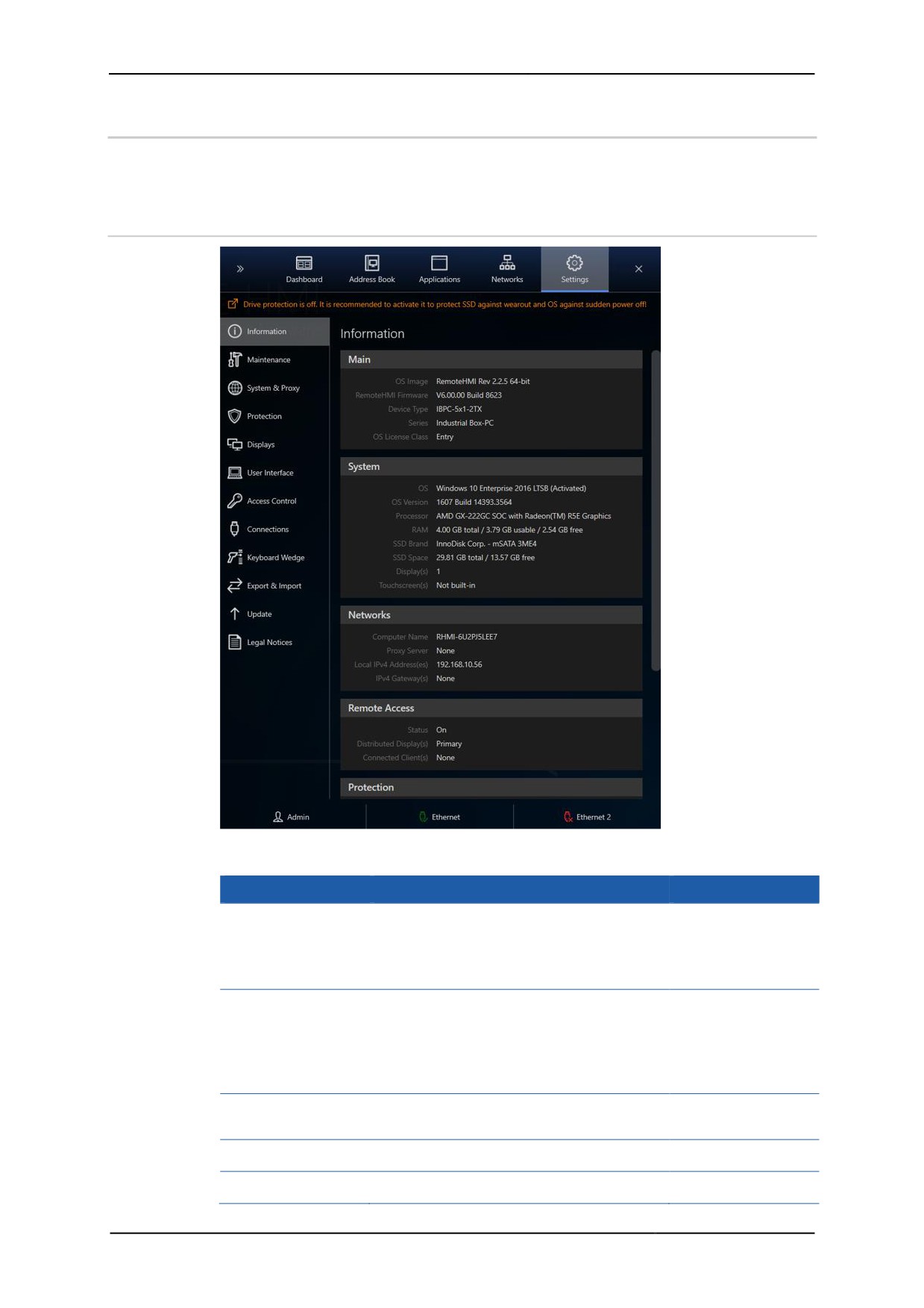
The Information menu lists the current system data, settings and configurations.
The menu contents vary depending on the device platform.
Menu
Contents
Main
Essential system information, OS image and firmware version
System
Information on hardware and operating system
This varies depending on the device type.
Network
Information on computer name and addresses of the proxy
server, the device and the gateway
Remote Access Information on the status of the remote connections
Protection
Up-to-date information on system security
Submodules
List of sub-module versions
8.3
Maintenance
Use the Maintenance menu to carry out operations at the Windows system level.
• Change to Admin account of Windows user interface
• System restart
• System shutdown
• Settings reset
• Pairing Bluetooth devices
• Calling up the Windows event log
• Remote HMI Activating the Pro Licence
• Activating windows (via Internet or telephone)
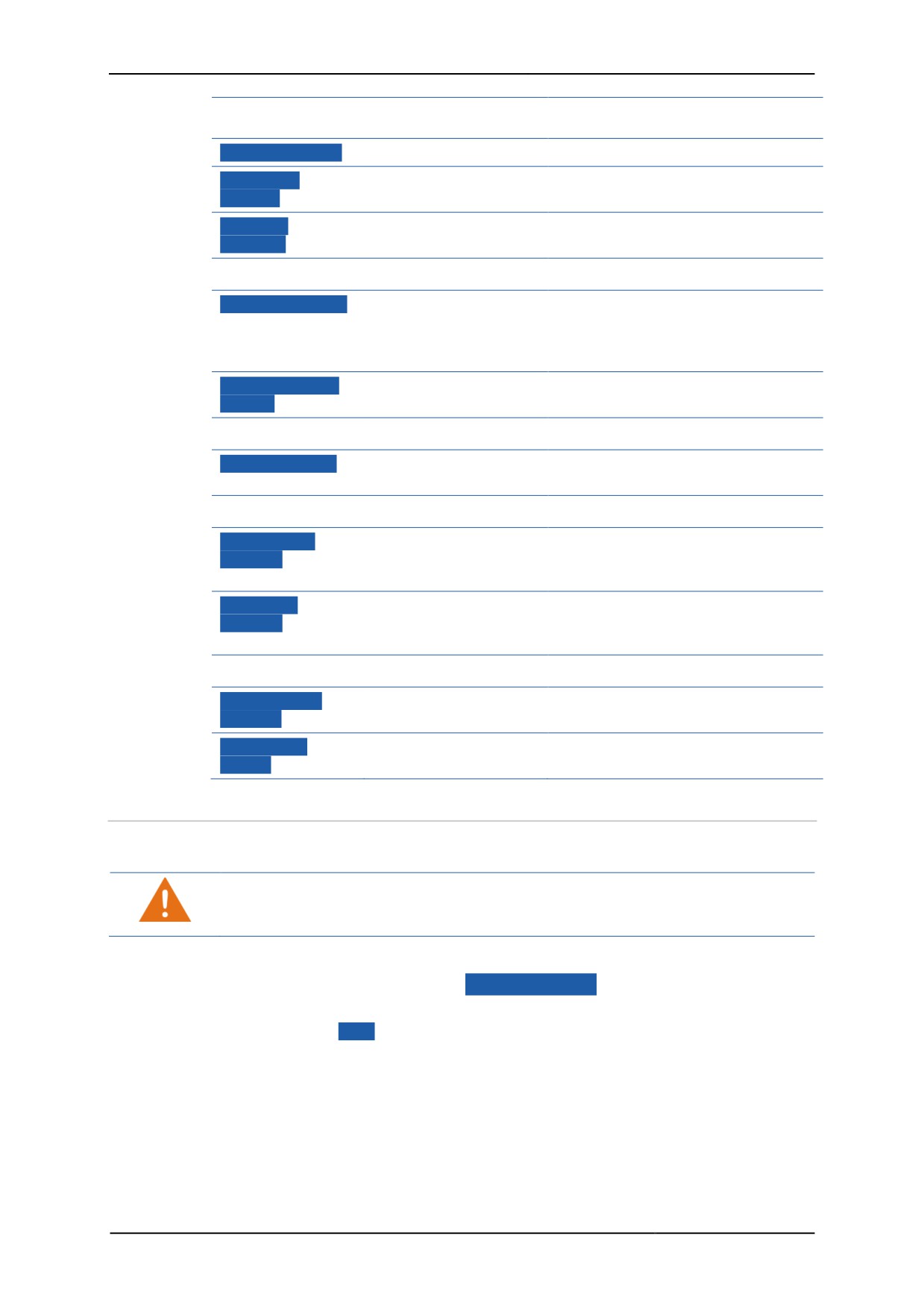
Functions in the Maintenance menu
Main
Maintain System System maintenance
Permits log-in to the Administrator
51
Remote HMI
Manual
account with the regular Windows
user interface
Restart System
System restart
Restarts the system
Shutdown
System shutdown
Shuts down the system
System
Reset all
Reset all settings
Reverts device to factory settings
Settings
Device
Add/Pair Device
Opens Windows system control to
Adding / pairing a
add peripheral devices or to pair
device
Bluetooth devices with the Thin
Client
Adjust Pointing
Opens the mouse system properties
Adjust mouse
Device
at the Thin Client
Event log
View event log
Opens the event log Viewer of the
Open event log
Thin Client
Pro Edition License Activation
Activate Pro
Activates Pro Licence online
License
Activates Pro Licence
(requires Thin Client with internet
access)
Apply Pro
Activates single Pro Licence offline
License
Applies Pro Licence
(requires PC/terminal device with
internet access)
Windows Activation (only shown if Windows LTSB not activated)
Activate over
Activates Windows LTSB (requires
Activate via internet
Internet
Thin Client with internet access)
Activate by
Opens telephone dialogue for
Activate via phone
phone
activation of Windows LTSB
8.3.1
Change to Admin account of Windows user interface
Enables you to perform system maintenance in the Administrator account and install
applications on the Thin Client, for example.
Settings at system level may cause the device to malfunction. Only change to the
system level if you are familiar with advanced settings. If not, ask your network
administrator for help.
1. Open the Maintenance menu.
2. In the Main section, click on Maintain System .
¾ A safety check will pop up.
3. Confirm with Yes .
¾ The system changes to the login window, allowing you to log in to the
Administrator account of the regular Windows user interface.
4. Make the required system changes.
9 Usually, a system restart is required to apply the changes.
52
Remote HMI
Manual
8.3.2
System restart
1. Open the Maintenance menu.
2. In the Main section, click on System .
¾ A safety check will pop up.
3. Confirm with Yes .
9 The system restarts.
8.3.3
System shutdown
Certain changes to the firmware require a Thin Client restart.
1. Open the Maintenance menu.
2. In the Main section, click on Shutdown System .
¾ A safety check will pop up.
3. Confirm with Yes .
9 The system shuts down.
8.3.4
Settings reset
You can reset the firmware settings to their factory state.
A reset means:
• Address book entries are deleted
• The application list is deleted
• Network configuration is reset to "automatic"
The following settings will not be reset:
• Keyboard layout
• Windows text and element size
• Computer Name
You can use the Export function to save the address book entries, the application list
and network settings separately. Then use the Import function to restore the intact
settings (see Import and Export).
Only carry out a reset if you are familiar with the configuration of the Thin Client.
1. Open the Maintenance menu.
2. In the Main section, click on Reset all Settings .
¾ A safety check will pop up.
3. Confirm with Yes .
9 The system is reset to its factory state.
8.3.5
Pairing or adding a peripheral device
Use this dialogue to pair or add peripheral devices such as USB or Bluetooth devices.
1. Open the Maintenance menu.
2. Connect the new device to the Thin Client
3. In the Device section, click on Add/Pair Device .
¾ The system changes to the system level and the "Control Panel/Hardware and
Sound/Devices and Printers" window.
4. Add a new device via "Add a device".
5. The system dialogue for adding a device will start.
53
Remote HMI
Manual
6. Choose the device type.
7. Follow the instructions of the system dialogue.
8. The device is ready to be used once the device drivers have been installed and
the device has been configured.
9. Test whether the device is working properly.
8.3.6
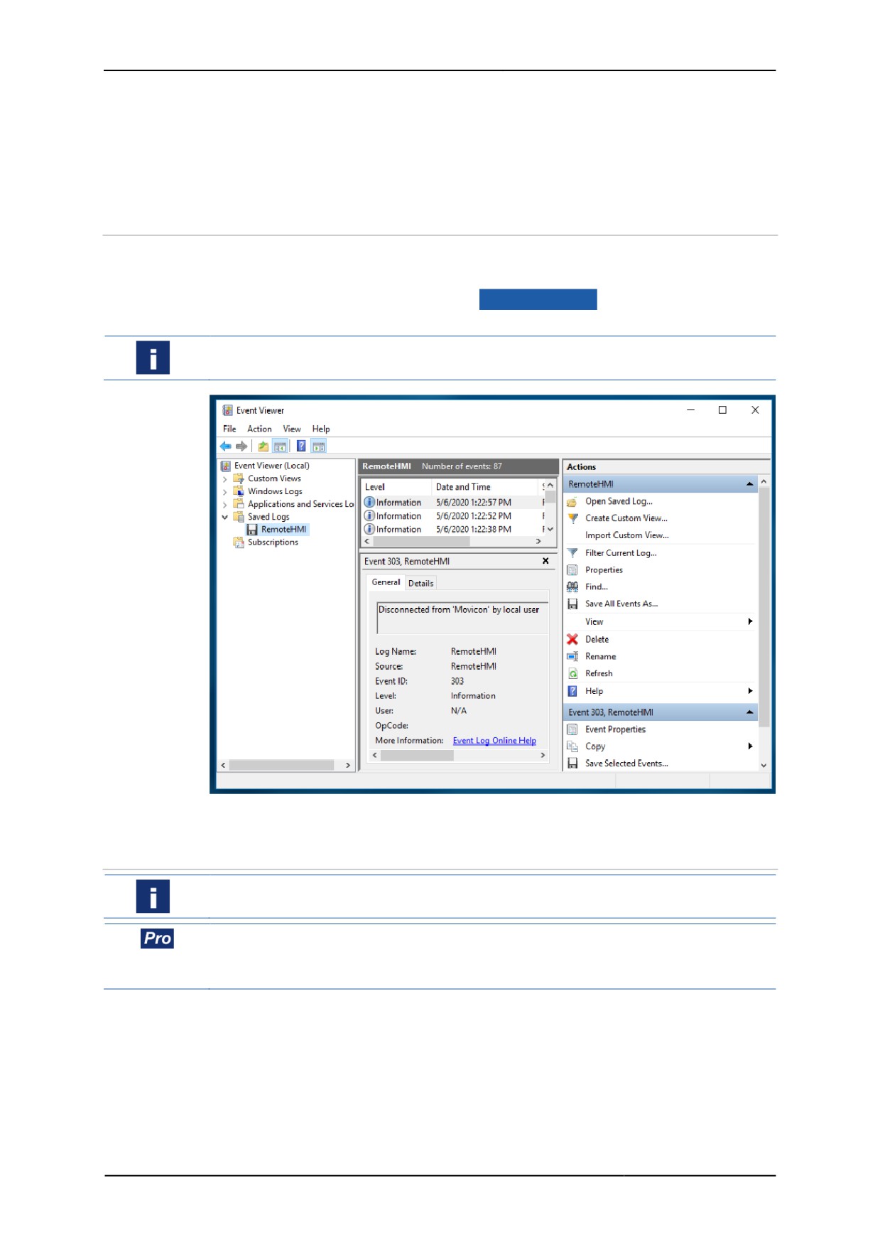
Calling up the event log
Opening the event log
1. Open the Maintenance menu.
2. In the Event log section, click on View Event Log .
¾ The system will change to the "Event Viewer" at the system level.
It may take a while for all of the recent events to be listed. Wait until the list is
complete.
9 You can find all events on the list.
8.3.7
Activating the Pro Licence
The UWF filter must be deactivated before you can carry out this process.
If the Thin Client has internet access, you can activate the Pro Licence online via the
firmware.
If not, you need to request the activation code from remotehmi-licensing.stahl.de .
Activating the licence online via internet access
1. Open the Maintenance menu.
2. Make sure the Thin Client has internet access.
3. In the Pro Edition License Activation section, select the Online function.
4. Under Product key, enter the licence key you received.
5. Under Company Name, enter your company name.
6. Under Name, enter the name of the licence holder.
54
Remote HMI
Manual
7. Under Email Address, enter the e-mail address of the licence holder.
8. Click on Activate Pro License .
¾ The system will issue a message.
If the activation has been successful, the Pro Edition License
Activation section will be hidden.
Activating the licence offline
In order to activate the licence you will need the device's installation ID and the
product key (licence key). You will also need a device with internet access.
1. Open the Maintenance menu.
2. In the Pro Edition License Activation section, select the Offline function.
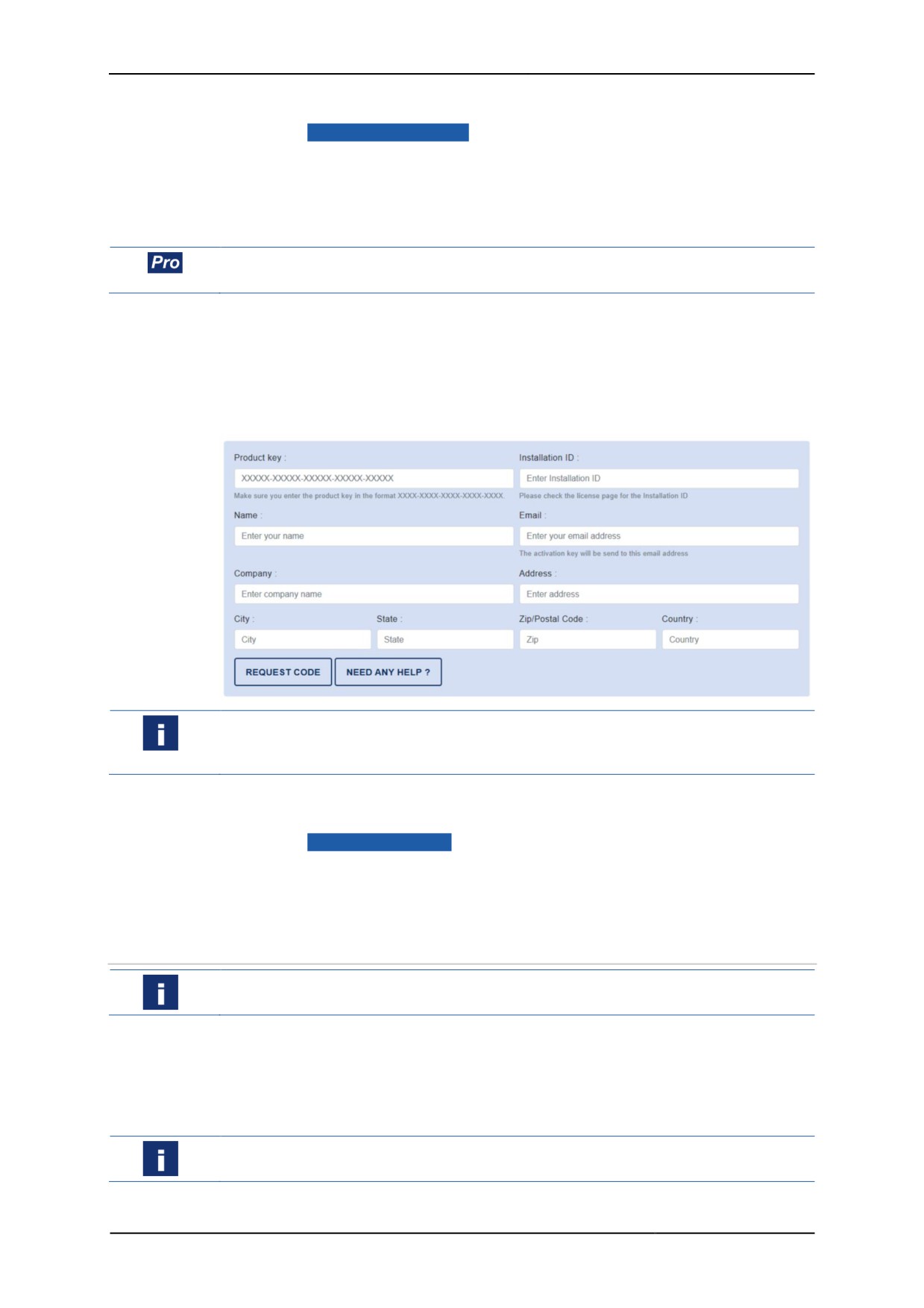
3. In the browser, go to the following website: remotehmi-licensing.stahl.de.
4. Select "License Activation".
5. Fill in the form and request the activation code.
You will receive an e-mail with the activation code to the e-mail address specified in
the form. This may take up to five minutes. If you receive no such e-mail, please check
your spam folder.
6. In the Maintenance menu, enter the product key under Product key and the
activation code under Activation Code.
7. Click on Apply Pro License .
¾ The system will issue a message.
If the activation has been successful, the Pro Edition License
Activation section will be hidden.
8.3.8
Activating windows
The UWF filter must be deactivated before you can carry out this process.
The Windows 10 LTSB operating system is pre-installed on delivery. If Windows 10
LTSB is deactivated after a system reset for example, you can re-activate it via the
telephone or internet access. A system dialogue will guide you through the re-
activation via telephone.
Activating the operating system via telephone
Activation is carried out via Microsoft's telephone service.
1. Open the Maintenance menu.
55
Remote HMI
Manual
2. In the Windows Activation section, click on Activate by phone .
¾ The Windows activation system dialogue will start.
3. In the Select your country or region window, select your country or region.
4. Click on Next to navigate to the Call and provide your installation ID
window.
5. Select the telephone number given and follow the instructions given in the
telephone dialogue.
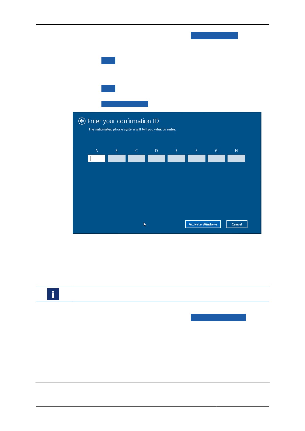
6. Click on Next to navigate to the Enter your confirmation ID window.
7. Enter your confirmation ID.
8. Click on Activate Windows to activate the operating system.
¾ The system will issue a message.
If the activation has been successful, the Windows Activation section will
be hidden.
9 The Information menu will list the activated operating system under
System.
Activating the operating system via an internet access
The Thin Client needs to have internet access.
1. Open the Maintenance menu.
2. In the Windows Activation section, click on Activate over Internet .
¾ This process may take up to one minute.
3. Wait until the system issues a message.
¾ If the activation has been successful, the Windows Activation section will
be hidden.
9 The Information menu will list the activated operating system under
System.
8.4
System and proxy settings
The System & Proxy menu features the following options:
56
Remote HMI
Manual
• Change computer name
• Changing the proxy server settings for VNC und Remote HMI Device Manager
(RDM)
• Configuration of the remote access
• Saving login data for the Admin account
Accept or reject settings
1. Click on Apply to accept the settings.
2. Click on Revert to reject the changes.
8.4.1
Change computer name
The Thin Client can be addressed via the IP address or the computer name in the
network. The computer name can be used for remote access to the Thin Client via
VNC, for example. The computer name should therefore be unique in the network.
1. Enter the computer name under Computer Name.
It might make sense in large networks to enter a description too, in order to be able to
identify the device faster.
2. Enter an informative description of the device under Description.
8.4.2
Changing the proxy server settings
Use the proxy server to control and limit access to internet resources, for example.
The client request is forwarded to the target server with the IP address of the proxy
server.
Using a proxy server
1. Identify the IP address or the network name of the proxy server.
2. Activate the Use a Proxy Server function.
3. Enter the IP address or the network name of the proxy server.
Not using a proxy server
1. Deactivate the Use a Proxy Server function.
8.4.3
Configuration of the remote access
Configuration of remote access to the Thin Client via VNC and RDM
1. Activate Allow configuration export/import via RemoteHMI Device
Manager to allow the export and import of the Thin Client configuration via the
RemoteHMI Device Manager.
2. Activate Allow remote access via VNC to allow the VNC remote access to
the Thin Client.
3. Enter the password for the remote control.
4. As an option, enter a password for remote access without operating permit.
5. Click on Advanced VNC Server Config if you need to change the VNC settings.
6. Click on Input blocking during remote access to define access behaviour
during a remote connection.
7. Activate Off to allow local and remote operation during remote access.
8. Activate Local to block local operation of the Thin Client during remote access.
57
Remote HMI
Manual
9. Activate Remote on local activity, inactivity timeout = 3 sec to block
the remote operation via local operation during remote access.
¾ This block is removed if no local operation occurs during a specified idle
period. The factory setting for this idle period is 3 seconds. This can be
adjusted.
10. To adjust the idle period, click on Advanced VNC Server Config .
8.4.4
Saving login data for the Admin account
You can save login data for access to the Windows Administrator account under
Windows Admin Account Login Credentials. The login data is required to
start applications via the firmware that require Administrator or other elevated rights.
If you save the login data,
• you no longer need to enter the data every time you start the app
• users who do not know the login data can start the app
1. Under Name and Password, enter the login data for the Windows Admin
account.
8.5
Protection
The Protection menu features the following options:
• Activate firewall and virus protection
• Activating write protection for the SSD
• Activating the USB lockdown
• Configuration of system behaviour during restart
Accept or reject settings
1. Click on Apply to accept the settings.
2. Click on Revert to reject the changes.
8.5.1
Activate firewall and virus protection
We recommend you activate the Windows firewall and the virus protection, and permit
all necessary security updates. In its factory state, these functions are activated.
Activating Windows security
1. Activate the Windows Firewall.
2. Activate the Windows Defender.
The automatic download of security updates requires the Thin Client to have internet
access. If the function is deactivated, you have to manually monitor, acquire and carry
out updates at the system level.
3. Activate the Windows Security Updates to permit the installation of security
updates.
8.5.2
Activating write protection for the SSD
The Unified Write Filter (UWF) is a write protection for the SSD and can be activated
in the Protection menu. Use the UWF to protect the SSD from accidental writing. It
transfers all write access to an overlay buffer in the RAM.
It thus prevents premature wear-out of the SSD and a corruption of system files after a
sudden network failure. Also, viruses and Trojans are not permanently stored in the
system, since all changes stored in the overlay buffer are deleted when the device is
switched off.
58
Remote HMI
Manual
For the memory protection (UWF) to be activated the system needs to be restarted.
Activating the data memory protection
1. In the Protection menu, activate the Drive Protection (UWF) function.
2. Confirm the request for a restart.
9 After the restart, the data memory protection is activated.
8.5.3
Activating the USB lockdown
Depending on your security concept, you can block the use of USB devices or permit
the use of connected USB devices in the Protection menu. The use of other
devices can be permitted via the Teach-In function
Blocking the use of USB mass storage devices
1. Under USB Lockdown, activate the Block USB mass storage devices only
function.
2. Confirm your selection with Apply .
9 All USB storage devices are blocked.
Blocking the use of new USB devices
Use this function to block all USB devices that are not or have never been connected
to the Thin Client.
1. Open the Protection menu.
2. Under USB Lockdown, activate the Block access to USB devices function.
3. Activate Block new USB devices only.
4. Confirm your selection with Apply .
¾ The specifications of the connected USB devices will be saved.
9 New USB devices are blocked.
Permitting the use of connected USB devices
1. Under USB Lockdown, activate the Block access to USB devices function.
2. Connect the USB devices you want to permit.
3. Activate Block all USB devices except connected.
4. Confirm your selection with Apply .
¾ The specifications of the connected USB devices will be saved.
9 All registered USB devices are cleared for use.
Clearing further USB devices for use (Teach-In)
1. Under USB Lockdown, activate the Block all USB devices except
connected.
2. Deactivate Block access to USB devices.
3. If applicable, remove already connected USB devices and connect the new ones.
4. Activate Block new USB devices only.
5. Repeat steps 2 to 4 to add more devices.
6. When you have added all devices, click on Apply .
9 All registered USB devices are cleared for use.
8.5.4
Configuration of system behaviour during restart
The HORM function (Hibernate Once Resume Many) allows for a fast start of the Thin
Client from a fixed system image (snapshot). After the start, the system is in exactly
59
Remote HMI
Manual
the same state as when the last HORM snapshot was taken. This means that running
applications of the Pro version do not have to be restarted, but are available right
away.
Taking a snapshot (image of main memory) requires a system restart.
• Back up your device configuration so you won't lose any data (see Import and
Export).
Taking a snapshot of the main memory
1. Activate the memory protection under Drive Protection (UWF).
2. Activate the Resume System from same snapshot on every device
startup function.
3. Confirm your selection with Apply .
4. Confirm the request for a restart.
5. Click on Snapshot to create an image of the main memory.
6. Confirm the request for a restart to create the snapshot and restart the system.
The restart may take some time.
If the system does not start properly, you can use the "Recovery Stick" to return it to
its factory state. The stick is part of the delivery.
Depending on the recovery stick you can also save the device configuration as a
backup.
8.6
Display settings
The Display menu features the following options:
• Adjusting display settings
• Adjusting multi-display settings
The following parameters are available to adjust the screen display:
• Resolution: resolution and orientation
• Multi Display: order (topology) and main display (if more than one display is
connected)
• Scaling: scaling
• Windows Text and Items: size of text and image elements for Windows
applications
• Screen Saver: screen saver
• Backlight Auto Dimming: automatic dimming of backlight (for a touchscreen)
Accept or reject settings
1. Click on Apply to accept the settings.
2. Click on Revert to reject the changes.
8.6.1
Adjusting display settings
Adjusting resolution
1. Under Resolution, select the resolution of connected displays (6 max.).
2. Activate Portrait Mode to display screen content in portrait mode.
60

Remote HMI
Manual
Adjusting scaling
1. Activate Always stretch to fullscreen to always display screen content in
full screen mode.
¾ This function may result in a distorted display.
2. Activate Maintain aspect ratio to maintain the aspect ratio of the screen
content.
Changing Windows text and element size
The settings are only valid for local applications and RDP connections with Windows
10/Server 2012.
A greater size makes the touch screen easier to operate. Setting the size to over
100 % may result in a faulty display of local apps and apps executed via RDP.
• Select the desired size of Windows elements. We recommend 125 %.
• If local apps and those executed via RDP are displayed incorrectly, reduce the
setting to 100 %.
Switching on the screen saver
1. Activate the screen saver under Screen Saver.
2. Under After user inactivity of, specify the interval after which the screen
saver should be activated (1 to 60 minutes).
3. Click on Advanced to open the screen saver settings.
4. Select a screen saver and confirm your selection.
5. Open the Display menu.
9 The screen saver starts after a period of inactivity greater than the one
specified.
Automatic dimming of backlight
To increase the service life of the backlight we recommend you activate the
Backlight Auto Dimming.
1. Under Backlight Auto Dimming, activate the automatic dimming of the
backlight.
2. Under After user inactivity of, specify the interval after which the dimming
function should be activated (1 to 60 minutes)
3. Under to brightness level, specify the level to which the backlight should be
dimmed (1 % to 80 %).
9 The backlight is dimmed to this level after a period of inactivity greater than
the one specified.
8.6.2
Adjusting multi-display settings
The Eagle and Manta series devices can use another Thin Client as an additional
display. A virtual display is simulated at the main device, whose content can be
displayed on the additional screen via a VNC connection.
You can adjust the resolution and orientation for each display. You can also specify
the order (topology) and the main screen.
The name of the displays used in the firmware is that of the port at which the display is
connected.
61

Remote HMI
Manual
Adjusting the display order
1. In the Topology field, select the resolution of the display in question.
2. Activate the Clone function if you want to display the screen contents on both
displays.
3. Activate the Extend if the second display should be an extension of the main
display.
4. Under Primary Display Position, select the main display (left, right).
8.7
User Interface
The User Interface menu features the following options:
• Changing the size of the menu and the virtual keyboard
• Changing the keyboard layout
• Configuring user interface functions
Accept or reject settings
1. Click on Apply to accept the settings.
2. Click on Revert to reject the changes.
8.7.1
Changing the size of the menu and the virtual keyboard
It is not possible to change the keyboard via the firmware on Shark devices with Intel
i7 CPU.
Adjusting the size of the menu and the keyboard
1. Open the User Interface menu.
2. Under RemoteHMI Menu, use the scroll bar to adjust the size of the menu.
3. Under Virtual Keyboard, use the scroll bar to adjust the size of the keyboard.
Restoring device-specific factory settings
1. Open the User Interface menu.
2. Under RemoteHMI Menu, click on Default to restore the device-specific
factory settings for the menu size.
3. Under Virtual Keyboard, click on Default to restore the device-specific
factory settings for the keyboard size.
8.7.2
Changing the keyboard layout
The factory setting for the keyboard layout is the US layout (QUERTY). This applies to
the virtual and external keyboards (optional) The language layout is independent of
the design, coding, position and number of keys on the physical keyboard.
The Thin Client system console is set to the US layout, and this can NOT be changed.
The firmware supports various language layouts for the virtual and external
keyboards. The country codes for the language layouts are those listed in ISO 3166-1,
subsection ALPHA-2.
Country code
Name of country
BE
Belgium
BR
Brazil
CH
Switzerland
CZ
Czech Republic
62

Remote HMI
Manual
Country code
Name of country
DE
Germany
DK
Denmark
ES
Spain
FI
Finland
FR
France
GR
Greece
HU
Hungary
IT
Italy
NL
Netherlands
NO
Norway
PL
Poland
PT
Portugal
RU
Russian Federation
SE
Sweden
SI
Slovenia
TR
Turkey
US
United States of America
Changing the keyboard layout
1. Open the User Interface menu.
2. Under Keyboard Layout, select the keyboard layout you want.
3. If the keyboard layout you want is not listed, use Add/Remove to add another
layout.
8.7.3
Configuring user interface functions
Hotkey for opening the firmware
You can specify how to open the firmware:
• The hotkey toggles the dashboard between closed and minimised state (standard)
• The hotkey toggles the dashboard between closed, minimised and expanded state
(Hotkey toggles all 3 menu states)
Use Ignore hotkeys if RemoteHMI menu is closed to specify whether the
hotkeys for calling up remote connections and applications should be ignored when
the dashboard is closed. The defined hotkeys are only effective if the dashboard is
open. Use this function to use the same hotkeys for different purposes.
If you have defined a hotkey for opening the dashboard, this hotkey will always be
active. It is not affected by this function.
Configuring the user interface
1. Open the User Interface menu.
2. Activate Show computer name in title to show the computer name in the
minimised dashboard.
3. Activate Auto hide after connect to hide the dashboard after the connection
has been successfully established.
63
Remote HMI
Manual
4. Activate Hotkey toggles all 3 menu states to toggle between all three
dashboard states via the hotkey.
5. Define the hotkey for opening the dashboard.
6. Activate Ignore hotkeys if RemoteHMI menu is closed if the hotkeys
should be ignored when the RemoteHMI menu is closed.
8.7.4
Configuring how changes are applied
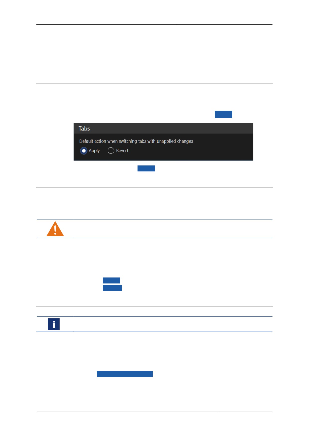
1. Open the User Interface menu.
2. Activate Apply if you wish to apply the changes after leaving the register.
¾ The changes are applied once you change to a different register.
3. Activate Revert if you wish to apply the changes via the Apply button.
¾ If you don't click on Apply , the changes will be discarded.
8.8
Keyboard Wedge
The Keyboard Wedge function sends ASCII-based data from a serial interface as
keyboard-generated characters to the host. The transmitted data are interpreted by
the target application as real keyboard input. Use this function to transform scans from
readers such as barcode scanners or RFID readers into keyboard input.
This process requires Administrator authority.
The Keyboard Wedge menu features the following options:
• Adding a device
• Parameterising the COM interface
Accept or reject settings
1. Click on Apply to accept the settings.
2. Click on Revert to reject the changes.
8.8.1
Adding a device
Installing a driver of a USB mass storage device
Deactivate the UWF filter to install the device driver.
1. Check whether the Thin Clients meets the system requirements of the input
device.
2. Make sure that the USB mass storage device is known or deactivate the USB
lockdown.
3. Open the Maintenance menu.
4. Go to Add / Remove Device to open the Thin Client system settings.
5. Install the device driver on the Thin Client.
6. Connect the input device to a free COM port. The name of the COM port depends
on the HMI device platform.
64
Remote HMI
Manual
7. Open the Keyboard Wedge menu.
8. Activate Simulate keyboard input via a connected reader/scanner
device.
9. Click on
+ Add / Auto Connect to connect the device.
8.8.2
Parameterising the COM interface
The configuration of the COM interface has to conform with the reader's specifications
to ensure correct data transmission.
Port
Specifies the serial connection where the reader's data is received
The name of the port depends on the device platform.
Baud rate
Specifies the data transmission rate of the COM port, must
correspond to that of the reader
2400 / 4800 / 9600 / 19200 / 38400
Data Bits
Specifies the length of the transmitted data bits
7: a character is 7 bits long
8: a character is 8 bits long (usual value)
Stop Bits
Specifies the number of bits signifying the end of a data
transmission process
1: stop bit is one bit long (usual value)
1.5: stop bit is 1.5 bits long
2: stop bit is two bits long
Parity
Specifies whether and how the parity test bit should be calculated
NONE: no bit testing process
EVEN: sum of the bits of a character to be transmitted is an even
number
ODD: sum of the bits of a character to be transmitted is an odd
number
1. Open the Keyboard Wedge menu.
2. Go to Serial Communication to select the COM port of the connected device.
3. Select a suitable baud rate for the connected device.
4. Specify the following parameters Data Bits, Stop Bits and Parity for the
serial interface.
¾ An active connection is shown in the status.
Configuring the handling of control characters
You can specify whether control characters for a line break sent by the barcode
scanner should simulate the pressing of the Enter key. This may be necessary so that
a scanned barcode is correctly completed and applied.
CR: carriage return
LF: line feed
1. Activate Translate CR to Enter-key to use "CR" as a control character.
2. Activate Translate LF to Enter-key to use "LF" as a control character.
65
Remote HMI
Manual
Adjusting server keyboard layout
For all scanned characters, and control characters in particular, to be processed
correctly, the keyboard layouts of both devices must conform. If the Thin Client is set
to US layout, this layout must also be selected for the connected server. For
connections via a KVM box this layout must also be selected in the user interface of
the KVM box.
The following options are available under Server Keyboard Layout:
US American keyboard layout: QWERTY
DE German keyboard layout: QWERTZ
FR French keyboard layout: AZERTY
1. Set Server Keyboard Layout to "US" to ensure faultless data transmission
Specifying data transmission delay
KVM Keystroke Delay specifies the delay before the next character is transmitted
to a KVM box. This delay ensures that no character is lost during a fast data
transmission to the host. The standard value usually suffices.
1. Only increase this value if characters are lost in the transmission.
2. Use the scroll bar or the arrows to adjust the delay from 1 to 50 ms.
8.9
Access Control
Use the Access Control menu to activate the three-tier user control and to
configure the automatic user logout.
Accept or reject settings
1. Click on Apply to accept the settings.
2. Click on Revert to reject the changes.
8.9.1
Activation of user roles
Activation of user roles
1. Open the Access Control menu.
2. Under Main, activate the 3-tier access control.
3. Activate Limit Operator access to Dashboard to hide the dashboard's
register bar from the operator.
¾ Operators can only see the dashboard data.
4. Under Login Passwords, enter different passwords for the "Engineer" and
"Admin" user roles.
5. Repeat the passwords. If the passwords are incorrect, the system will issue an
error message.
6. Click on Apply to accept the settings.
9 Users with roles "Engineer" and "Admin" have to logon with their passwords.
66
Remote HMI
Manual
8.9.2
Activating automatic logout
An automatic logout can be specified for the Admin and Engineer user roles. A user is
automatically logged off if he or she has been inactive for more than the pre-defined
logout time.
1. Open the Access Control menu.
2. Activate Auto Logout to activate the automatic user logout.
3. Specify the logout time under after user not operating RemoteHMI Menu
for (1 to 60 minutes).
8.10
Connections
The Connections menu features the following options:
• Allowing multiple simultaneous connections
• Auto reconnect
• Automatic check of host status
Accept or reject settings
1. Click on Apply to accept the settings.
2. Click on Revert to reject the changes.
8.10.1
Allowing multiple simultaneous connections
Requires a Pro licence.
Use the Allow Multiple simultaneous connections function to allow parallel
use of multiple remote connections (multi-session connections). This enables you to:
• Change between remote connections without having to terminate a connection
• Display several remote connections on one split screen
• Display several remote connections on two or more screens
Activating multi-session connection
1. Open the Connections menu.
2. Activate Allow Multiple simultaneous connections to allow the set-up of
several remote connections.
8.10.2
Auto reconnect
Go to On connection loss, auto reconnect to specify an interval after which a
reconnect is attempted after a connection has been lost.
This function must be activated separately for each remote connection in the address
book entry.
• Open the Connections menu.
• Under On connection loss, auto reconnect after, specify after how many
seconds a reconnect should be started (1 to 30 seconds).
8.10.3
Automatic check of host status
The Connection Health Check function is used by the Thin Client to send
cyclical pings (echo requests) to all servers configured in the address book. The result
of these requests is shown as the connection status in the address book.
The connection health check only works properly if the servers' firewalls permit
answering to an echo request.
67
Remote HMI
Manual
You can switch off this function if you do not require an echo request. In this case the
status of the connection is not shown in the address book
Activating health check
1. Open the Connections menu.
2. If you are using a firewall, check whether the firewall permits echo requests, and
activate the echo request.
3. Activate Ping servers to show reachable state on Address Book
buttons to check the remote connections constantly.
4. Click on Apply .
9 The Thin Client monitors the remote connections and shows the status of the
active connections.
If the echo request from the host is not possible or not wanted, deactivate Ping
servers to show reachable state on Address Book buttons.
The remote connections are not checked. Not connection status is shown.
8.11
Import and Export
The firmware supports the import and export of most settings to the encrypted
"RemoteHMI.config" file. This file can be exported to a USB mass storage or a
network directory. A filter can be used for the import to specify which settings should
not be imported (e.g. network settings).
This function enables you to
• Restore the device configuration after a system reset
• Copy the device configuration to another Thin Client
The Import & Export menu features the following options:
• Importing a device file
• Exporting a device file
This process requires Administrator authority.
8.11.1
Importing a device file
The UWF filter must be deactivated before you can carry out this process.
USB mass storage in hazardous areas
Only use intrinsically safe USB mass storage devices in hazardous areas.
A USBi stick is available for operations in hazardous areas.
You can exclude the following settings from the import:
• Application List (see App management)
• Network Settings (see Network)
• Access Control Password (see Access Control)
Make sure you know the defined passwords before starting the import.
Importing a configuration file from a USB mass storage device
1. If the USB lockdown is activated, make sure the USB mass storage device is
known. Otherwise, deactivate the USB lockdown.
2. Connect the USB mass storage device.
68

Remote HMI
Manual
3. Open the Import & Export menu.
4. Select the configurations you do not require from the import filter.
5. Activate USB Flash Drive.
6. Click on Import .
¾ The progress of the import is shown.
¾ If the process has been completed successfully, the firmware will issue a
message.
7. If an error message is issued, check whether the USB mass storage device has
been inserted correctly and that it is not write-protected.
8. Remove the USB mass storage device before restarting the device.
If you do not remove a bootable Recovery PE Lite USB mass storage, the device will
expect the installation of the firmware during the restart.
9. Click on Apply to apply the imported settings.
10. Restart the device to activate the changed configuration.
Importing a configuration file from a network directory
1. Save the import file on the network directory.
2. Select the configurations you do not require from the import filter.
3. Activate Network.
4. Click on Select to select the network directory in Windows Explorer.
5. Click on Import .
¾ The progress of the import is shown.
¾ If the process has been completed successfully, the firmware will issue a
message.
6. Click on Apply to save the imported settings.
7. Restart the device to activate the changed configuration.
8.11.2
Exporting a device file
Exporting a configuration file to a USB mass storage device
1. If the USB lockdown is activated, make sure the USB mass storage device is
known. Otherwise, deactivate the USB lockdown.
2. Connect the USB mass storage device.
3. Activate USB Flash Drive.
4. Click on Export .
¾ The USB mass storage device is checked.
¾ If it contains no configuration file it will be saved immediately.
5. If it already contains a configuration file, you need to confirm that the existing file
will be written over.
¾ If the process has been completed successfully, the firmware will issue a
message. The RemoteHMI.config file is saved in the root directory of the USB
mass storage device.
6. Remove the USB mass storage device.
If you do not remove a bootable Recovery PE Lite USB mass storage, the device will
expect the installation of the firmware during the restart.
Exporting the configuration file to a network directory
1. Activate Network.
2. Click on Select to select the network directory in Windows Explorer.
3. Click on Export .
¾ The network directory is checked.
69
Remote HMI
Manual
¾ If it contains no configuration file it will be saved immediately.
4. If it already contains a configuration file, you need to confirm that the existing file
will be written over.
¾ If the process has been completed successfully, the firmware will issue a
message. The RemoteHMI.config file is saved on the network directory.
8.12
Updates
Go to the Update menu to update the firmware from a USB mass storage device or a
network directory.
This process requires Administrator authority.
The UWF filter must be deactivated so that the firmware can be saved.
The menu will show the following information
• Installed: revision status of the installed firmware
• Available: available firmware, appears when an update file has been found
• Source: source of the available update, appears when an update file has been
found
8.12.1
Carrying out a firmware update
USB mass storage in hazardous areas
Only use intrinsically safe USB mass storage devices in hazardous areas.
A USBi stick is available for operations in hazardous areas.
Carrying out a firmware update from a USB mass storage device
1. If the USB lockdown is activated, make sure the USB mass storage device is
known. Otherwise, deactivate the USB lockdown.
2. Connect the USB mass storage device.
3. Click on Check for Update .
¾ The firmware trawls through the connected USB devices for available
updates.
¾ If an update is available it will be shown under Available.
4. Click on Install Update to install the update.
¾ The installation process starts.
Caution!
During this process the firmware will be restarted.
Do not interrupt the process and do not switch off the operating terminal.
¾ If the update has been installed, the menu will show a change protocol.
5. Remove the USB mass storage device.
Updating the firmware from a network directory
Our Support department will provide you with the update file.
1. Store the update file on the network directory.
2. Click on Select to select the network directory in Windows Explorer.
3. Click on Check for Update .
¾ The firmware trawls the network directory for available updates.
¾ If an update is available, it will be shown under Available.
4. Click on Install Update to install the update.
70
Remote HMI
Manual
¾ The installation process starts.
Caution!
During this process the firmware will be restarted.
Do not interrupt the process and do not switch off the operating terminal.
9 If the update has been finished, the system will issue a message.
71

Remote HMI
Manual
9
Useful tips
9.1
Error fixing
Touchscreen operation is inaccurate
Cause
How to fix it
Who
Touchscreen is dirty
• Clean display
Operator
Incorrect calibration
• Calibrating the touchscreen
Operator
Damaged display front
• Replace (repair) display
Engineer
Base station display is black
Cause
How to fix it
Who
Cable connection between base
• Check cable for damage.
Engineer
station and HMI device
• Check connector is inserted
interrupted
properly
• Replace defective parts.
Screen is black and keyboard is lit
Cause
How to fix it
Who
One-off fault due to electrical
• Restart Remote HMI.
Engineer
surge, for example
Screen is black and keyboard is not lit.
Cause
How to fix it
Who
Cable connection between base
• Check cable for damage.
Engineer
station and HMI device
• Check connector is inserted
interrupted
properly
• Check fuse.
• Replace defective parts.
The network connection is frequently interrupted or is unstable
Cause
How to fix it
Who
Cable not correctly connected
• Check wiring of the HMI device.
Engineer
inside the terminal box
Cable too long
• Contact Support / CSO
Engineer
System fails to restart after request to do so
Cause
How to fix it
Who
The most recent process caused
• Use recovery stick to reset
Engineer
a fatal system error.
system to factory state.
Bluetooth barcode scanner is not working
Cause
How to fix it
Who
Battery too weak
• Recharge battery.
Engineer
• Replace battery.
Barcode scanner not paired with
• Pair barcode scanner and base
Engineer
base station
station.
Cable connection between base
• Check cable for damage.
Engineer
station and HMI device
• Check connector is inserted
72

Remote HMI
Manual
interrupted
properly
• Replace defective parts.
Wrong passkey for connection
• Enter correct passkey (see
Engineer
was entered
barcode scanner documentation)
Barcode scanner defective
• Replace or repair defective
Engineer
barcode scanner.
Wired barcode scanner is not working
Cause
How to fix it
Who
Cable connection between
• Check cable for damage.
Engineer
barcode scanner and base
• Check connector is inserted
station interrupted
properly
• Replace defective parts.
Barcode scanner defective
• Replace or repair defective
Engineer
barcode scanner.
No connection possible between Remote HMI Device Manager and Thin Client
Cause
How to fix it
Who
Incorrect network configuration
• Check network configuration.
Engineer
Access from Device Manager to
• Allow access in the User
Engineer
Thin Client not permitted
Interface menu.
9.2
Activating VNC server system on the host
The following explains the procedure for the TightVNC server.
In order to be able to establish a VNC connection, the VNC server system must be
activated on the host. The VNC service acquires the IP address needed for this
connection from the settings of the PC's network connection. Depending on the
configuration, the IP address is specified manually or allocated by a DHCP server. In
the firmware's address book, this IP address is defined as the server IP of the VNC
connection.
The way this connection is established depends on the settings of the VNC server and
can either be
• a direct connection that is not password-protected
• a connection with VNC password
• a connection with Windows password
9.2.1
VNC server parameters
The following parameters are necessary to configure the VNC connection. The actual
name may vary depending on the VNC server system used.
VNC server address
The VNC server address is the same as the server IP address or the server name.
The VNC server systems usually have several ways to find out the address with which
the server can be addressed in the network.
In addition to the IP address, port numbers can be allocated in the settings of the VNC
server, with which the server can be addressed in the network.
The target address of the Host PC must be located in the network of the Thin Client or
must be contactable from the Thin Client.
73
Remote HMI
Manual
Ports
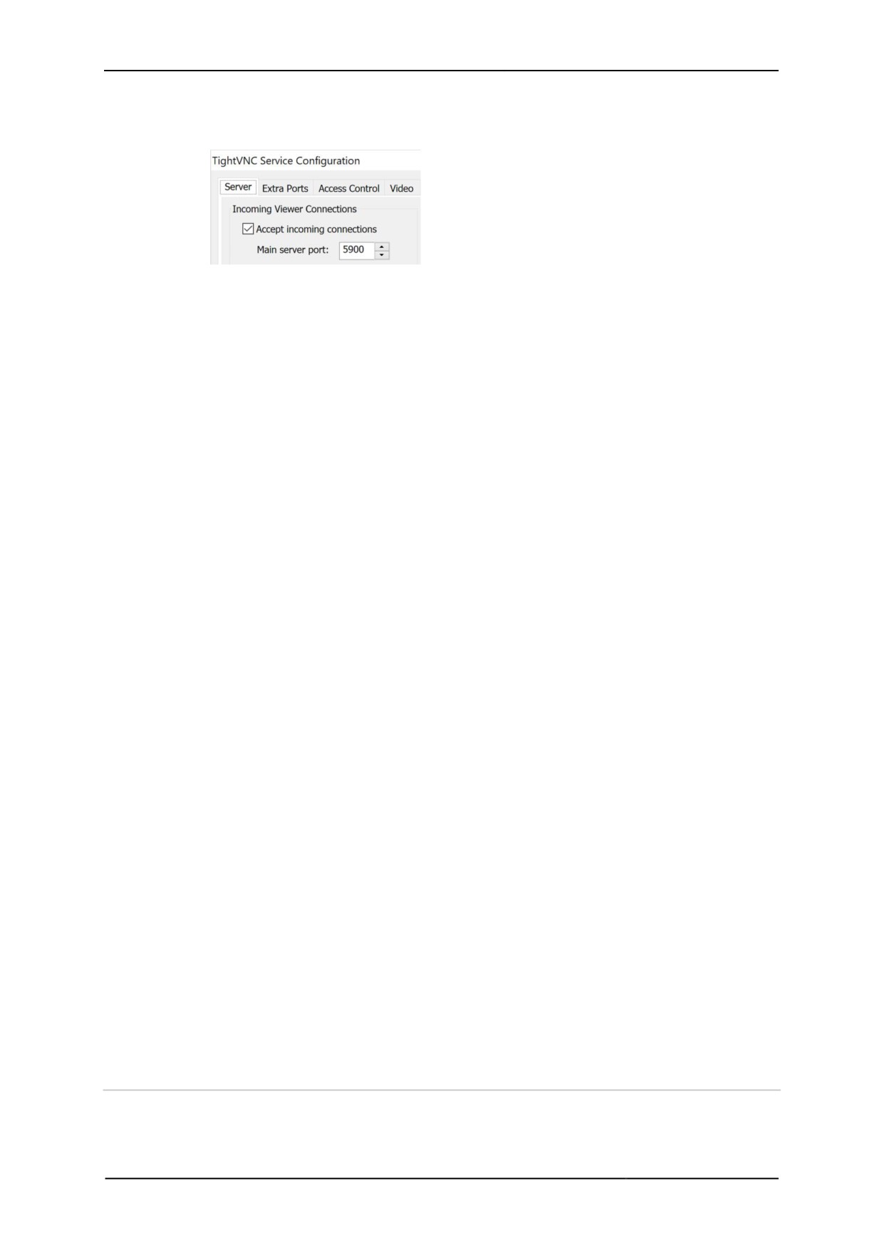
Accept connections on port
Defines the server connection port for data
transmission (standard port 5900).
If you are using a different port due to network
conflicts you need to configure this port. Check the
settings of a firewall.
VNC password
VNC server applications authenticate users of a VNC connection via a password. The
following password procedures are available:
None
No password is defined. The VNC server on the
host allows access to each remote PC (Remote
HMI) requesting a VNC connection via its address.
VNC password
Defines one or more passwords (depending on
VNC server application) which the VNC server
system requests from the Client for authentication
purposes.
Windows password
Uses the Windows access authentication. The VNC
server system grants the client access to the host if
logged on with the valid Windows password.
Single sign on
Uses Windows access authentication and
authentication via Windows-based login. The VNC
server system grants access to the client if the user
has entered a valid Windows login.
Encryption
Most VNC servers use encryption to protect the transmission of image, mouse and
keyboard data from unauthorised access.
Always on
Data is always encrypted
Prefer on
Data is always encrypted unless the Thin Client
requests no encryption (standard). This setting is
necessary if the configuration requests no
encryption.
Prefer off
Data is not encrypted unless the Thin Client
requests encryption. This setting is necessary if the
configuration requests encryption.
Prompt local user to accept connections
Allows the host user to accept or reject a connection request. Since the host is usually
used for direct remote access, this setting is not relevant for the Thin Client
connection.
Start VNC Server automatically with Windows
Specifies that the VNC server system is automatically activated when Windows is
started. If this function is not activated, the remote access must be explicitly started
after a system start of the host PC.
9.3
DRDC-Client connection
EMERSON's DeltaV®-Remote-Desktop-Connection-Client (DRDC) allows access to a
virtualised operator or engineering workstation within a DeltaV®-virtualisation
architecture. This way, applications that run on a distributed control system can be
accessed via the Ethernet.
74
Remote HMI
Manual
You can add a DRDC connection via an app in the Applications register (see
Adding apps).
Requires a Pro licence.
75