Remote HMI V6 Industrial-Grade Thin-Client Firmware. Manual (Firmware Version: 6.00.00) - page 1
Remote HMI V6
Industrial-Grade Thin-Client Firmware
Manual
Firmware Version: 6.00.00
Issue:
Remote HMI
Manual
Table of contents
1
About this documentation
3
1.1
Registered trademarks
3
1.2
Target group
3
1.3
Layout features
3
1.4
Contact details
4
2
Description
5
2.1
Function
5
2.2
Licencing models
6
2.3
Configuration file
6
2.4
Supported remote protocols
6
2.5
Security concept
8
2.6
Display resolutions
9
2.7
User interface
10
2.8
Remote HMI Device Manager
17
3
Quick start
19
3.1
Set-up of the network adapter
19
3.2
Set-up of remote connections
20
3.3
Test of remote connection
24
3.4
Activation of user roles
24
3.5
Further configuration options
25
4
First steps for the operator
26
4.1
Start menu
26
4.2
Using the virtual keyboard
26
4.3
Starting a remote connection
28
4.4
Using the dashboard settings
30
4.5
Starting applications
33
4.6
Calling up the status of the Ethernet connection
33
4.7
Using the multi-display mode
34
5
Address book
35
5.1
Address book options
35
5.2
Set-up of remote connections
36
5.3
Test of remote connection
39
5.4
Managing remote connections
39
6
App management
41
6.1
Options in the Applications register
41
6.2
Adding apps
43
6.3
Managing apps
44
7
Network
46
7.1
Options in the Networks register
46
1
Remote HMI
Manual
7.2
Adapter information
47
7.3
About DHCP
47
7.4
About DNS
47
7.5
Set-up of the network adapter
48
7.6
Teaming function
48
8
Settings
50
8.1
Options in the Settings register
50
8.2
Display of system information
51
8.3
Maintenance
51
8.4
System and proxy settings
56
8.5
Protection
58
8.6
Display settings
60
8.7
User Interface
62
8.8
Keyboard Wedge
64
8.9
Access Control
66
8.10
Connections
67
8.11
Import and Export
68
8.12
Updates
70
9
Useful tips
72
9.1
Error fixing
72
9.2
Activating VNC server system on the host
73
9.3
DRDC-Client connection
74
2

Remote HMI
Manual
1
About this documentation
This documentation describes the set-up and operation of the Remote HMI V6
Firmware, henceforth referred to as "firmware".
The Remote Device Manager, henceforth referred to as Device Manager, is available
for the configuration of the firmware and the administration of licences.
1.1
Registered trademarks
The products and services referred to in this documentation are registered trademarks
and as such the property of their manufacturers.
1.2
Target group
This documentation is intended for administrators and production engineers who are
authorised to parametrise HMI systems and set up remote connections.
1.3
Layout features
This documentation uses the following symbols, highlights and notes:
Notes on system security and how to avoid data loss
Important information on workflow and its optimisation
Notes on Pro licence functions
• List
Heading of an instruction
1. First step
¾ Interim result
2. Second step
9 Result of action
Apply
indicates a button on the user interface
Dashboard
indicates a register, menu or a function of the user interface
[F8]
indicates a key of the keyboard
3
Remote HMI
Manual
1.4
Contact details
R. STAHL HMI Systems GmbH
Adolf-Grimme-Allee 8
50829 Köln
Germany
Telephone:
+49 221 76806-1200
Facsimile:
+49 221 76806-4200
Homepage:
r-stahl.com/de
Contact data Support
Telephone:
+49 22176806-5000
E-mail
Support.dehm@r-stahl.com
4
Remote HMI
Manual
2
Description
2.1
Function
The Remote HMI V6 firmware is a Thin Client software developed for the process
industry which is supplied together with R. STAHL SERIES 500 operating devices. It is
used to establish and secure remote connections to one or more workstations or
application servers. This makes remote access from one operating station to one or
more workstations or servers possible.
System functions
Function
Description
Access Control
3-tiered access authority management
System settings and installation of applications by
administrator only
Auto Connect
Automatic connection to the host after start-up
Diagnosis function
Detection of network or host failure
Teaming (Backup)
Redundancy due to automatic switch to a different
network adapter
Network test
Integrated ping function to monitor the remote
connection
Clean touchscreen
Disabling the touchscreen function for cleaning
purposes
Touchscreen adjustment
Adjustment of the touchscreen by the user (brightness,
right mouse button, calibration)
The following functions are only available with a Pro licence:
Multi-session operation
Parallel remote connections enabling users to switch
fast between connections, or allowing for the
simultaneous display on a split screen
App management
Fast access to applications and application programs
Suitable for device platforms:
• EAGLE series 5X6
• MANTA series 5X7
• MANTA GMP series 5x9
• SHARK series 5X8
• Industrial Box PC
The devices are connected to the Ethernet via the Ethernet interface. The number of
available Ethernet adapters varies depending on the device platform.
Supported pointing devices
Various pointing devices such as trackball, joystick, touchpad and mouse module are
available as accessories. These are supported by the firmware, also in combination
with industrial keyboards. Should you require further information, please contact:
R. STAHL HMI Systems GmbH.
5
Remote HMI
Manual
2.2
Licencing models
The following licence models of the firmware are available for the Thin Clients:
• Basic
Basic licence for establishing remote connections, configuring the firmware and for
importing and exporting settings.
• Pro
Licence extension for using and managing applications, using multiple parallel
remote connections, importing and exporting settings and the support of the
Remote HMI Device Manager.
2.3
Configuration file
The configuration file contains the device parameters and the settings of the Thin
Client. They can only be opened at the Thin Client.
The "RemoteHMI.config" configuration file can be exported to the root file of a USB
mass storage device or a network directory. The exported file is encrypted and can be
imported after a reset or into another device, for example (see Import and Export).
2.4
Supported remote protocols
The HMI operating stations and the Industrial Box PCs are integrated as Thin Clients
and use the available network resources. Depending on the network architecture and
access authority level, a remote connection can be established via the IP address to
any Ethernet station. The firmware supports the Remote Desktop Protocol (RDP),
Virtual Network Computing (VNC) and Keyboard Video Mouse over Internet Protocol
(KVM over IP). The Thin Client can use the firmware to call up applications installed
on the connected workstations or installed on virtual servers.
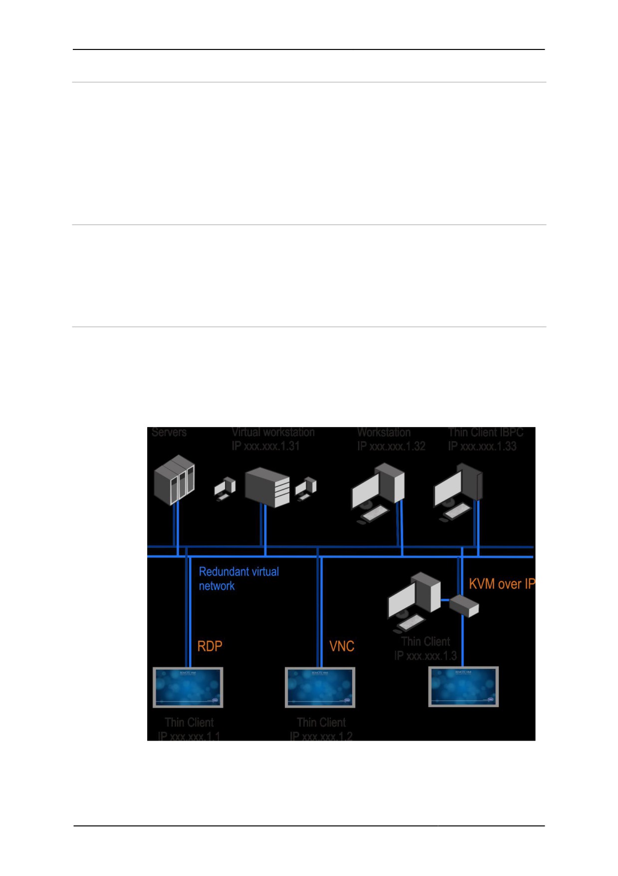
The illustration shows a redundant virtual network. It connects Thin Clients via an
RDP, VNC or KVM-over-IP connection with workstations and servers. In such a
network, every Thin Client can access connected systems and call up applications
from there.
6
Remote HMI
Manual
2.4.1
RDP
The Remote Desktop Protocol (RDP) is a protocol for remote access. It can be used
to display and control screen content of a remote workstation. RDP is an integral part
of all Windows operating systems.
A special session is started on the server for the RDP access, and only the connected
client can access this session.
The size of the displayed screen content is determined on the Thin Client's display
size. If the screen content is only displayed on one half of the Thin Client it will be
scaled accordingly.
A Windows server is required for several RDP connections to access one server. A
client access licence is required for each client to access and connect to the Windows
server. Licencing depends on the operating system of the server.
Either the computer name or the server IP address can be used for addressing.
If you want the option of redundant connections we recommend you use the DNS
naming system.
2.4.2
VNC
Virtual Network Computing (VNC) is a platform-independent server system. VNC
operates according to the Client-Server model.
The VNC service displays the screen content of a remote PC (server) on a local
computer (client) The client sends the keyboard and mouse actions to the remote
server. This way, the client can use the resources, applications and programs of the
server.
The server's display size determines the size of the displayed screen content. If the
server display screen ratio is different to that of the Thin Client, the screen content will
be compressed or displayed with black edges.
VNC allows multiple access to the server. The display of the clients is then
synchronised.
The VNC service must be installed on the remotely controlled PC (host). The Thin
Client accesses the VNC server via a VNC viewer application. The installation and
configuration of the VNC system on the server and the client requires administrator
access authority. The VNC communication between server and client does not require
this level of access authority.
VNC services are available from various providers. Depending on the VNC server,
these systems have different functionalities.
For detailed information and a description of the VNC service, please refer to the
documentation of the provider.
In order to be able to establish a VNC connection, the VNC server system must be
activated on the host. The VNC service acquires the IP address needed for this
connection from the settings of the PC's network connection. Depending on the
configuration, the IP address is specified manually or allocated by a DHCP server. In
the firmware's address book, this IP address is defined as the server IP of the VNC
connection.
The way this connection is established depends on the settings of the VNC server and
can either be
• a direct connection that is not password-protected
• a connection with VNC password
• a connection with Windows password
2.4.3
KVM over IP
KVM over IP provides remote access to keyboard-video-mouse systems (KVM). With
these systems, a workstation is connected with keyboard, mouse and screen via an
external KVM-over-IP box. The KVM-over-IP box is integrated into the network via an
7

Remote HMI
Manual
Ethernet interface. Data transmission is via the VNC protocol. A VNC service has
been installed to establish the connection. The workstation that is part of the KVM
system does not require a network connection or a software installation.
2.5
Security concept
2.5.1
System security
The Thin Client has been designed as a closed system based on Windows® 10 IoT
Enterprise 2016 LTSB.
As a standard, the Thin Client comes equipped with the Windows 10 IoT Enterprise
operating system and activated Windows 10 LTSB (Long Term Servicing Branch).
If Windows 10 LTSB is not activated (after a reset, for example), it can be activated
under menu item Maintain (see Activating windows).
We recommend you activate the firewall and virus protection and permit all necessary
security updates.
Any further measures to protect the process network are the responsibility of the
operator of the facility.
Overview of security functions
Function
Description
Operating system
Based on Microsoft 10 IoT Enterprise LTSB
Remote Desktop
Microsoft RDP 10 with security functions
Protocol
Firewall
Active Windows firewall as protection against network attacks
Unified Write Filter
Protection of the directory against integration of malware or
(UWF)
corruption of system files
HORM
Fast restart of a system image
USB lockdown
Individual lockdown or release of USB ports for USB terminals
and sticks
Virus protection
Active Microsoft Defender for virus protection; further virus
protection programs can also be installed
Access Control
Available remote connections and applications can be specified
via user roles
8

Remote HMI
Manual
2.5.2
User roles
The access control system of the Remote firmware is based on three user roles.
These are tiered in a hierarchy.
User role
Description
Operator
The operator can switch between the displays of the connected
(standard user)
systems and operate these systems remotely. The operator has
access to the basic settings. He or she cannot make any
changes to the firmware.
Engineer
The production engineer can set up, parametrise and delete
remote connections. With the Pro licence, the engineer can add
existing applications in the firmware. He or she cannot access
the Windows user interface of the Thin Client.
The engineer can adjust the following settings:
• Displays
• User Interface
• Connections
• Keyboard Wedge
Admin
The administrator has full access authority to the Windows user
interface of the Thin Client. In addition to the options available to
the production engineer, the administrator can install third-party
applications and drivers on the Thin Client. He or she can
configure the network, make system settings via the Remote
HMI menu user interface and log into the regular Windows user
interface as Admin.
The following adjustments in the Settings can only be made by
the administrator:
• Maintenance
• System & Proxy
• Protection
• Access Control
• Import & Export
• Update
The Admin and Engineer user roles can be password-protected in the "Access
Control" menu.
When the firmware is started up for the first time, the user roles are de-activated and
the firmware starts with the Admin user role. Password protection is not active.
The Admin and Engineer user roles should only be given to staff familiar with Thin
Client administration.
2.6
Display resolutions
The Thin Client supports the display of non-native display resolutions for all types of
connection. Non-native resolutions are those where the video output of the server
does not correspond to the actual physical resolution of the Thin Client display.
Resolutions from 640x480 (VGA) up to 2560x2048 (QSXGA) can be selected. The
display and scaling behaviour varies according to the connection type.
The supported HMI platforms correctly display every regular server display resolution
from VGA to QSXGA. The aspect ratio is maintained with the maximum possible
display resolution. Thus, the Thin Client can continue to be operated via the
touchscreen even if there are black edges.
9
Remote HMI
Manual
Display of an RDP connection
As a standard, the video output of the server is started with the native resolution of the
Thin Client.
Display of a VNC connection
The video output of the server is displayed in the maximum possible size whilst
maintaining the correct aspect ratio. Hardware or software are used to scale to
achieve the maximum possible image quality.
Server resolutions higher than the native Thin Client display resolution are fully
displayed. If the server resolution strongly differs from the native Thin Client
resolution, the display of small structures may be restricted. Scaling may be adjusted
as required to use the Thin Client display fully. This might result in a distorted display.
Display of a KVM-over-IP connection
The video output of the server is fully displayed in the maximum possible size whilst
retaining the correct aspect ratio, provided the server resolution is equal to or less
than the native Thin Client display resolution. Non-native resolutions might result in
black horizontal and/or vertical edges.
For server resolutions greater than the native Thin Client display resolution the Thin
Client switches to panning mode. Here, only part of the server image output is visible.
This section can be moved when the cursor stops at a screen edge.
2.7
User interface
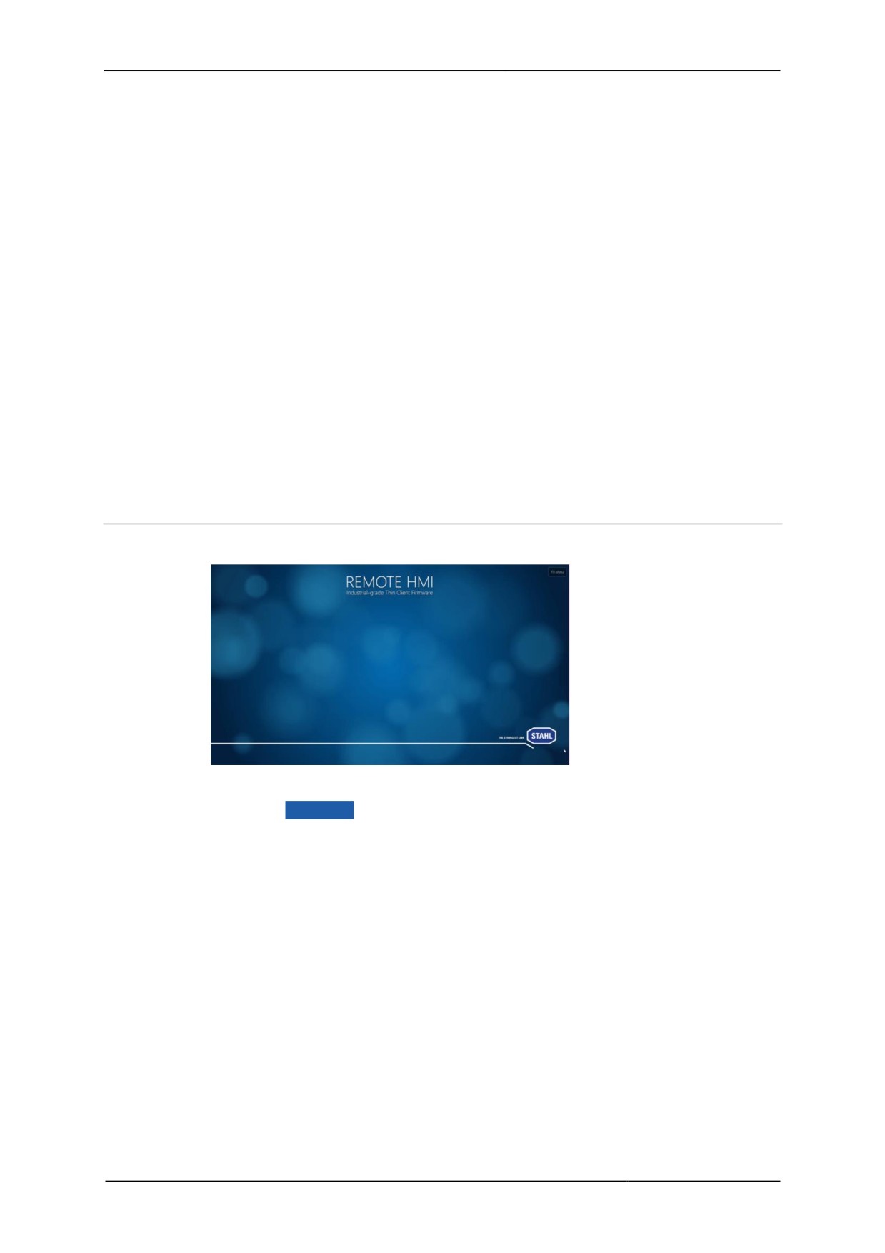
The system will start with the following screen.
You have the following options for opening the dashboard:
• via the F8 Menu button
• by pressing the [F8] function key
• by prolonged pressing of the keyboard icon
The [F8] function key can be changed in the User Interface menu.
10
Remote HMI
Manual
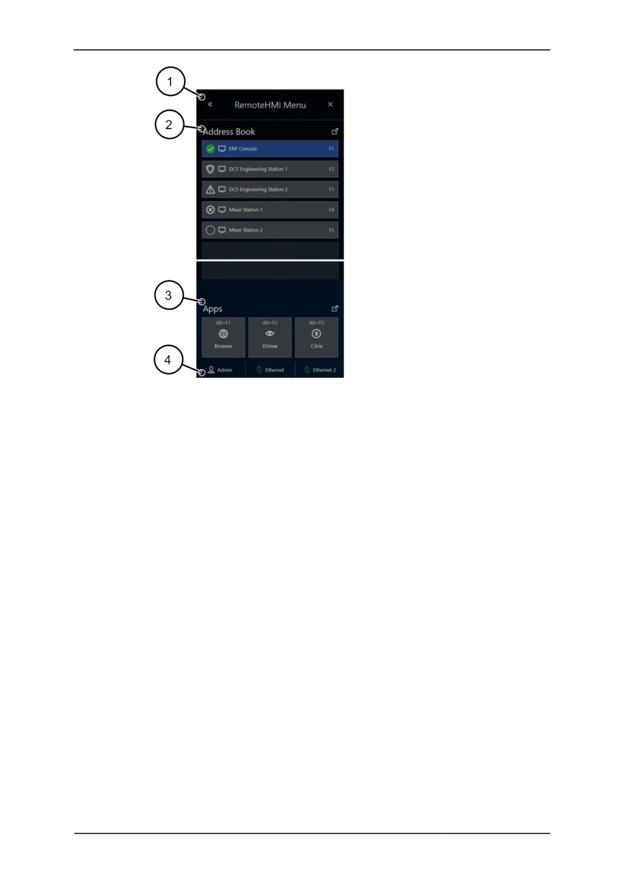
Minimised dashboard
1
Navigation element leading to expanded dashboard
2
Fast access to available remote connections
3
Fast access to applications (available for Pro licence if applications have been
installed and released)
4
User role, click button to open the log-on dialogue
11
Remote HMI
Manual
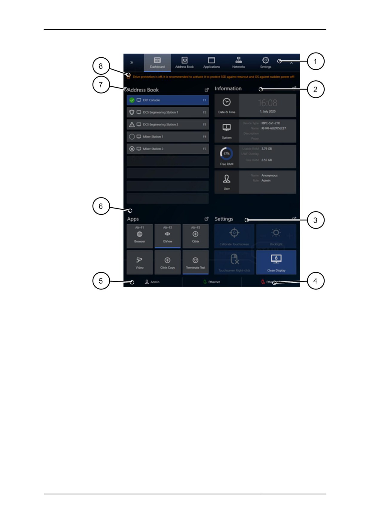
The contents of the expanded dashboard depend on the system configuration.
Dashboard
1
Register bar
2
System information
3
Basic settings for the HMI operator interface
4
Status of Ethernet connection
5
User role, click button to open the log-on dialogue
6
Fast access to applications (available for Pro licence, if applications have been
installed and set up)
7
Fast access to available remote connections
8
Notes on system security
12
Remote HMI
Manual
2.7.1
Register
The register bar contains the following functions:
Register
Description
Dashboard
Overview of address book, system and connection information,
basic functions and activated apps
Address Book
Diagnosis and management of remote connections
Applications
Display and management of applications
Networks
Display and set-up of the network adapters
Settings
Menus for display and set-up of system, security and network
parameters
2.7.2
Information
The system information contains the following data:
• Date & Time Date and time
• System Thin Client data
• Free RAM available memory
• User current user role
• Network 1 Status, IP address and speed for network adapter 1
• Network 2 Status, IP address and speed for network adapter 2
2.7.3
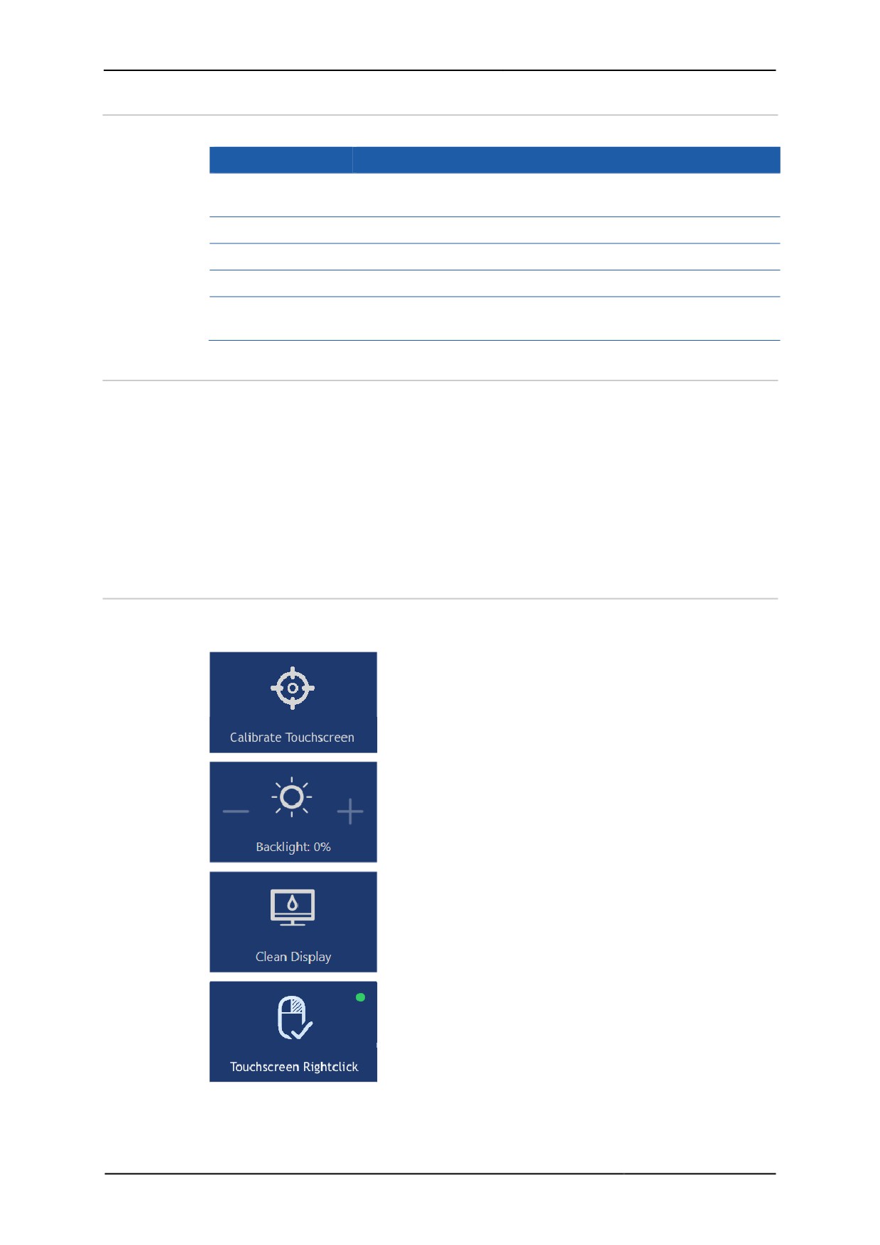
Basic settings
The basic settings contain buttons for operating the touchscreen. If no touchscreen is
connected, the functions are greyed out.
Button to start the touchscreen calibration. If two
touchscreens are connected you can calibrate them
separately.
Button to adjust the display backlight.
Button to deactivate the display touch function for 30
seconds Inadvertent activation of buttons during
cleaning is thus impossible.
Button to simulate a right mouse click on the
touchscreen, for example to call up the context menu
of applications.
13
Remote HMI
Manual
2.7.4
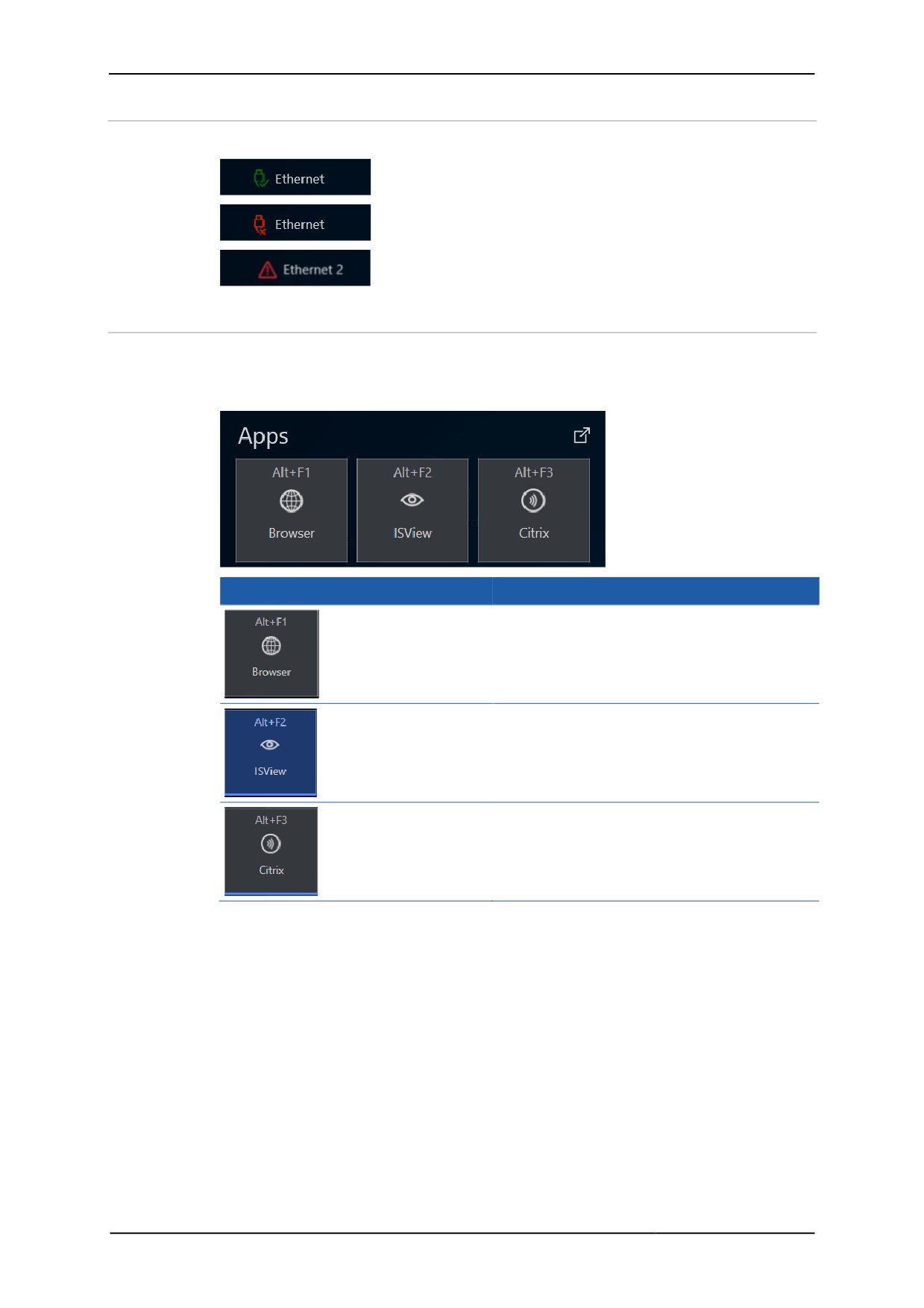
Status of Ethernet connection
This display indicates the status of the Ethernet connection.
Ethernet adapter is ready
Ethernet adapter is not ready
Conflict of addresses, Ethernet adapter is
not ready
2.7.5
Applications
Applications can only be used with a Pro licence of the firmware.
Once applications (apps) have been set up, they are shown as buttons. More than one
app can be started. The status of the app is shown.
Display
Meaning
inactive app
active app
app running in the background
14
Remote HMI
Manual
2.7.6
Address book
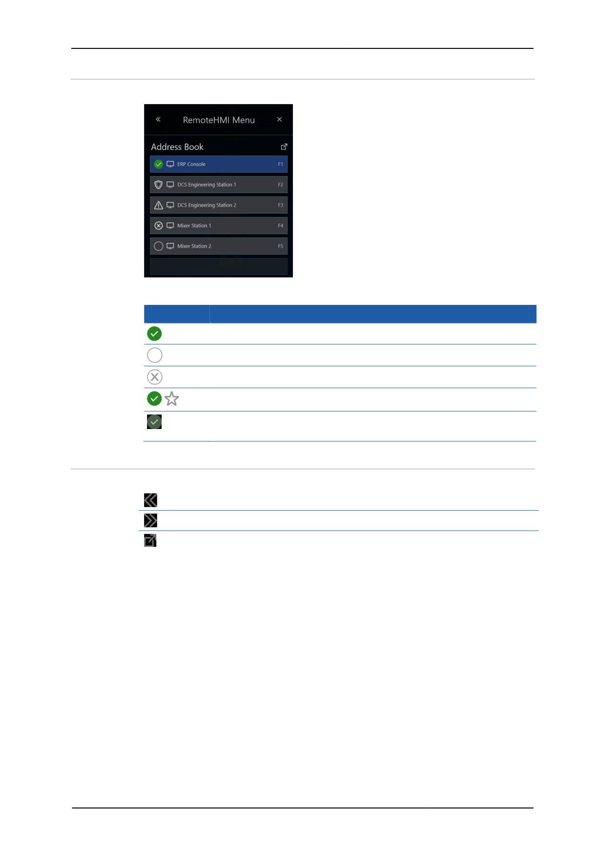
The remote connections can be selected from the address book.
Status of the remote connection
Symbol
Meaning
connected
not connected
connection not possible
default, will be connected automatically during start-up
connected, parallel remote connection, active in the background (multi-
session connections require a Pro licence)
2.7.7
Operating elements
Navigation elements
opens the expanded dashboard
minimises the dashboard
navigates to register or menu
15
Remote HMI
Manual
Operating elements
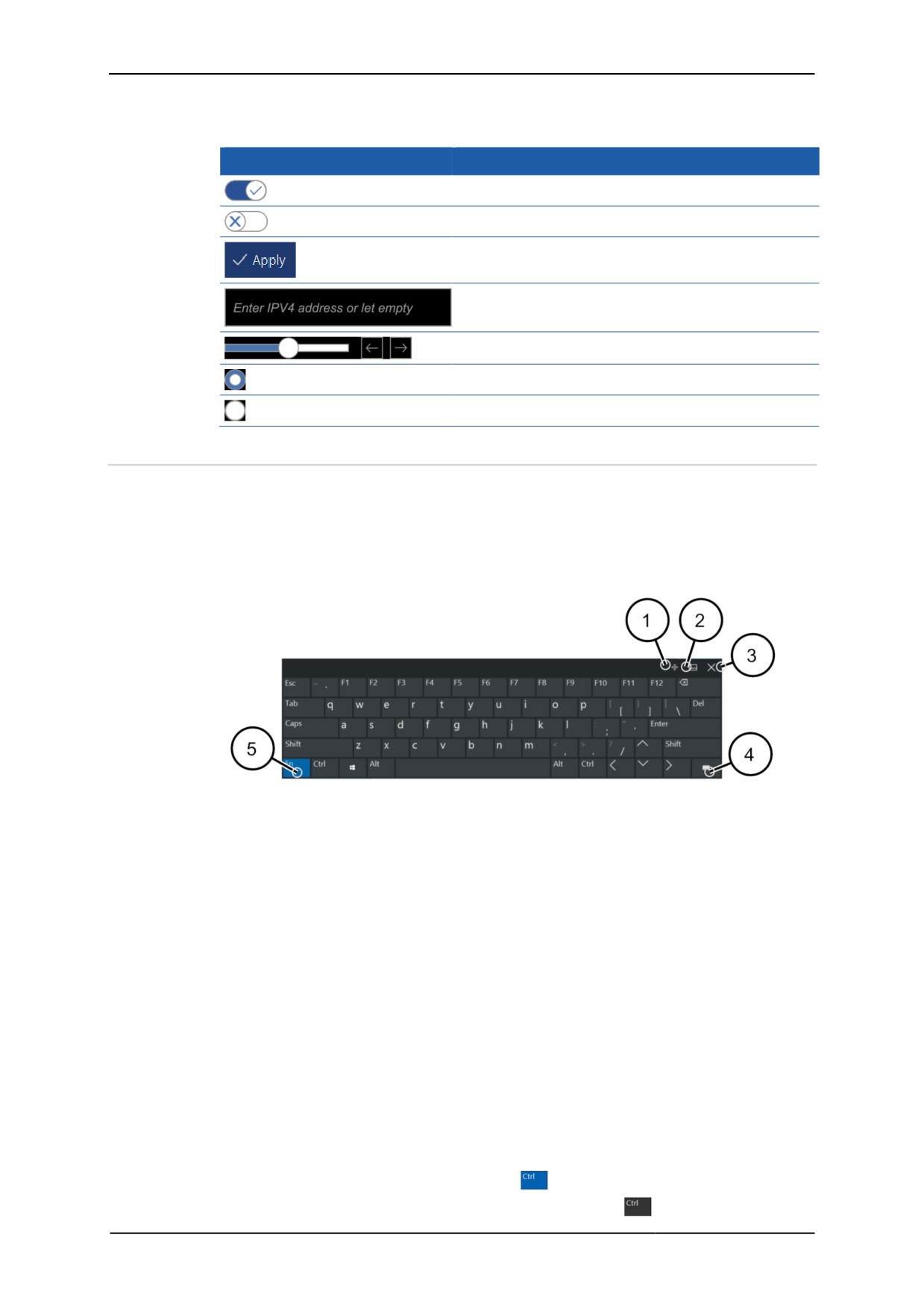
Operating elements vary depending on the menu.
Element
Meaning
Switch activated
Switch deactivated
Button
A greyed-out button is unavailable
Input field
Scroll bar
Check box activated
Check box deactivated
2.7.7.1
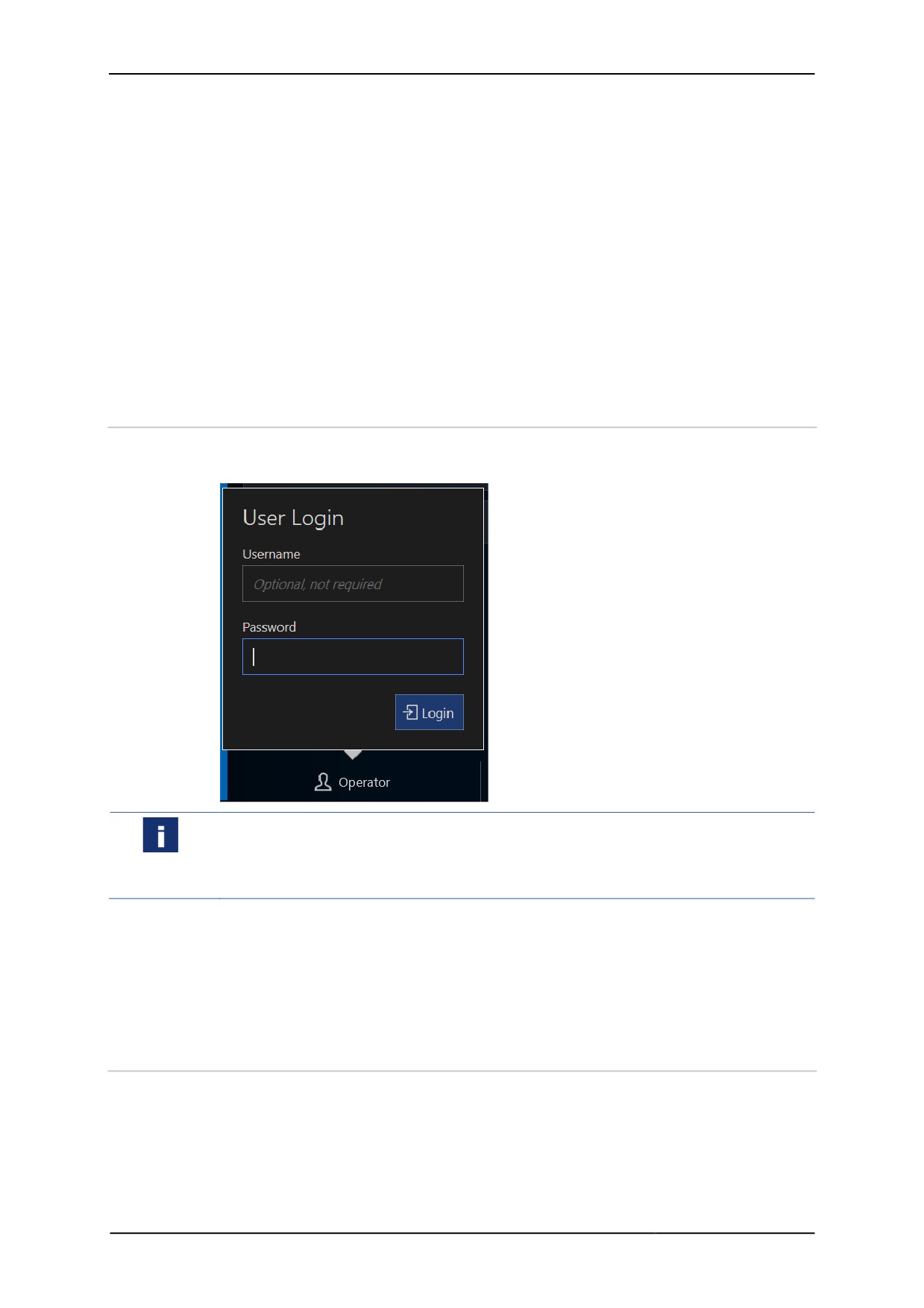
Virtual keyboard
The Thin Client has a virtual keyboard and can be operated without any further input
devices.
The virtual keyboard consists of several keyboard sections. These can be displayed or
hidden as required. The size of the keyboard can also be changed. This functionality
is managed via the KEYBOARD control section. The keyboard can be positioned and
adjusted via the following buttons:
Total view of virtual keyboard (US keyboard layout)
1
Free positioning of the keyboard
2
Positions keyboard at the bottom edge
3
Closes keyboard
4
Opens keyboard settings
5
Shows function keys
The virtual keyboard is automatically started when the Thin Client boots. The icon of
the virtual keyboard will appear at the top edge of the display.
During an active remote connection the icon of the virtual keyboard can be moved to
any position. The keyboard should then only cover less important parts of the
application. This position will be resumed whenever the remote connection is re-
established at some later date. The virtual keyboard does not have to be positioned
again.
Hotkeys
The Ctrl, Alt, Shift, Caps and Windows control keys on the touchscreen are used as
follows:
• Key has been touched, colour changes
• Key function has been executed, colour changes back
16
Remote HMI
Manual
Without a remote connection the control key combinations have no function.
Use the Windows key in combination with another key to use a function of the
Windows operating system. A double-click of the Windows key will open the start
menu.
The Caps key on the virtual keyboard also has a LED.
Cursor
For KVM-over-IP and VNC connections, the Thin Client displays two different cursors
showing the mouse position on the Thin Client and the host.
• Thin Client cursor: dot
• Host cursor: arrow
The cursors move asynchronously. Depending on the VNC server's performance there
may be time-lags with the remote pointer lagging behind.
2.7.8
Login
Login is only required when the user roles have been activated. Operators have
access to the system without login.
In the factory state, the user roles are deactivated and the Admin is the standard
user.
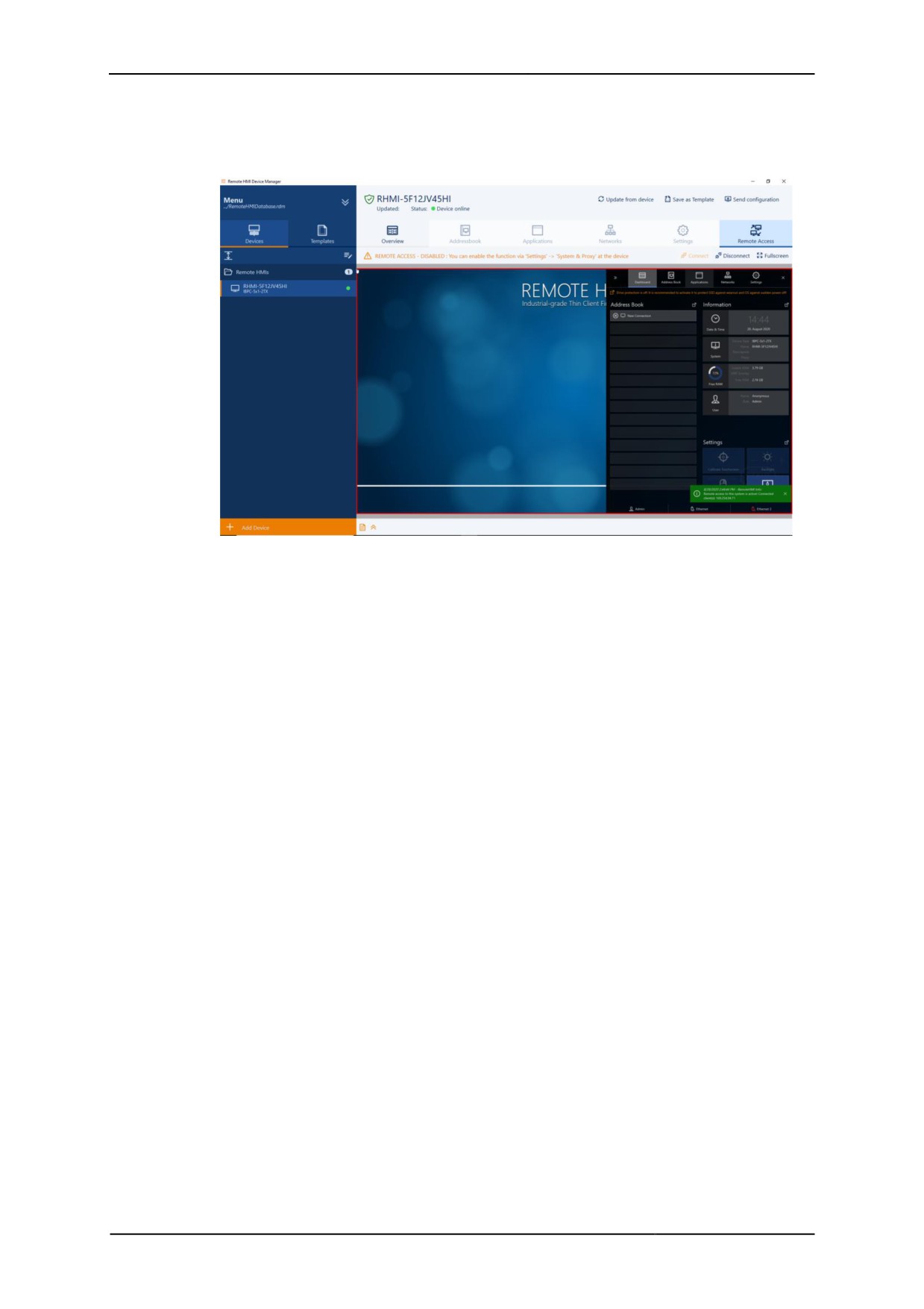
When the user roles have been activated, a password is required for the Engineer and
Admin user roles. A user name is not required.
Changing users
1. Open the User Login.
2. Enter the password.
3. Confirm with [Login].
9 The RemoteHMI menu will open.
2.8
Remote HMI Device Manager
The Remote HMI Device Manager is a supplement to the firmware. It is used for
central parametrisation of the firmware and for licence management. Device Manager
access must be granted in the firmware under the System & Proxy menu item.
Once access has been granted, several Thin Clients can be configured and
parameterised via templates with the same settings.
17
Remote HMI
Manual
Also, the Device Manager can access the Thin Client via the Remote Access
function. This remote access via VNC must be permitted under the System &
Proxy menu item.
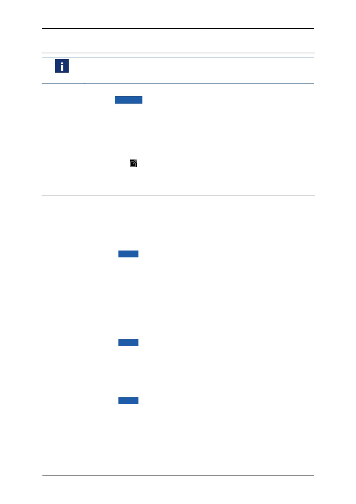
Remote HMI Device Manager accessing the firmware of an IBPC.
During parametrisation of the firmware, changed settings are not 'broadcast live'. The
local user can decline every change or postpone it to a different time.
18
Remote HMI
Manual
3
Quick start
Notes on first start-up
The firmware starts with the Admin user role. User roles and password protection are
not active. Once you have completed the configuration, activate the user roles.
You have the following options for opening the dashboard:
• via the F8 Menu button
• by pressing the [F8] function key
• by prolonged pressing of the keyboard icon
The [F8] function key can be changed in the User Interface menu.
Opening the dashboard
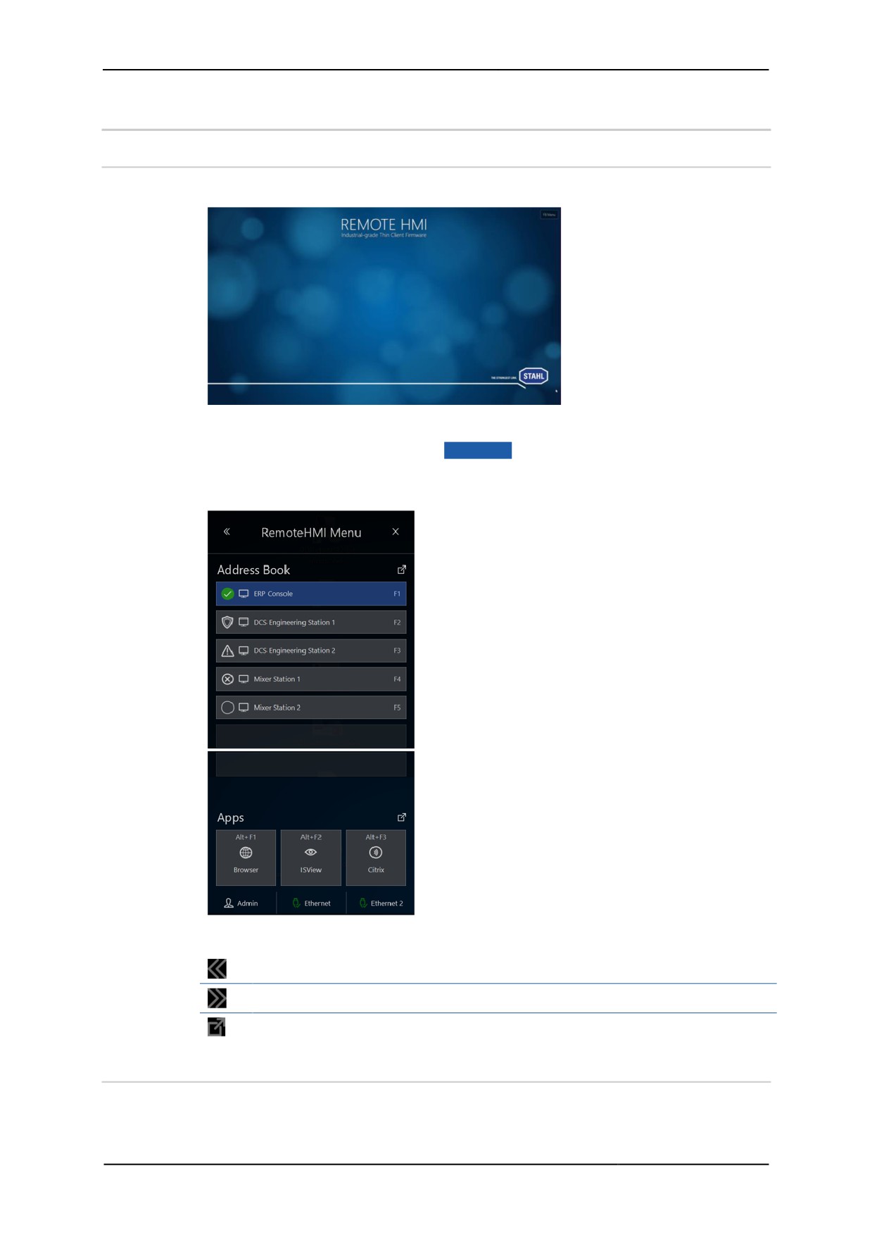
1. On the start screen, open the Remote HMI menu.
2. Navigate via
directly to the address book.
3. Or use the double arrow to open the expanded dashboard.
3.1
Set-up of the network adapter
As a factory setting, the automatic address allocation Auto config via DHCP is
activated.
Automatic set-up of the network address
1. Open the Networks register.
2. Check whether Auto config via DHCP is activated.
3. Click on Apply to start the automatic allocation by the DHCP server.
9 IP address, gateway and subnet mask are configured.
Manual set-up of network address
1. Open the Networks register.
2. Deactivate Auto config via DHCP to set up the address manually.
3. Under Local IP address, enter the IP address of the network adapter.
4. Under Subnet Mask, enter the subnet mask.
5. If you want the Thin Client to access a different network, enter the IP address of
the gateway under Gateway.
6. Click on Apply to accept the changes.
9 IP address, gateway and subnet mask are configured.
Automatic configuration of the DNS server
1. Open the Networks register.
2. Activate Auto DNS Server Addresses to activate the automatic address
allocation.
3. Click on Apply to accept the settings.
9 The IP addresses of the DNS servers that were found are registered.
19
Remote HMI
Manual
Manual configuration of the DNS server
1. Open the Networks register.
2. Under Primary DNS Server, enter the IP address of the first DNS server.
3. Under Secondary DNS Server, enter the IP address of the second DNS
server.
4. Click on Apply to accept the settings.
3.2
Set-up of remote connections
3.2.1
Notes on remote connections
Automatic logon at the server
The automatic logon at the server can be configured in the settings of the remote
connection. For this you need the user ID and the password for the server.
Only users with authority for remote access to the server can log on to the server.
Check the user authority at the server or the KVM box.
Display position of the remote connection
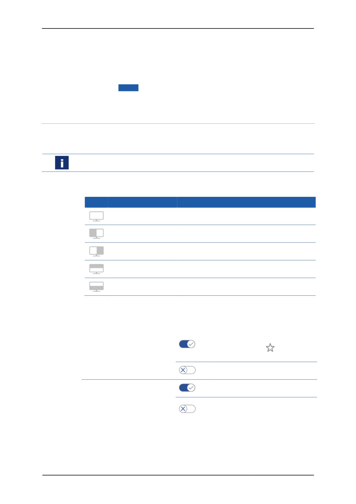
The following display options are available:
Symbol Name
Meaning
Full display
shows the full screen
Scales the remote screen content and displays it
Left display half
on the left hand side
Scales the remote screen content and displays it
Right display half
on the right hand side
Scales the remote screen content and displays it at
Upper display half
the top half
Scales the remote screen content and displays it at
Lower display half
the bottom half.
Behaviour of firmware when connection is lost
You can configure how the remote connection behaves during a system startup or
when it is lost, as follows:
Auto connect on system
Automatically establishes a
connection during system startup, is
startup
On
represented by the
symbol in the
address book entry
During a system startup the dial-up
Off
must be started manually
Auto reconnect on
Automatically reconnects after the
On
connection has been lost
connection loss
After the connection has been lost,
Off
the dial-up must be started
automatically
20
Remote HMI
Manual
For Pro licence users
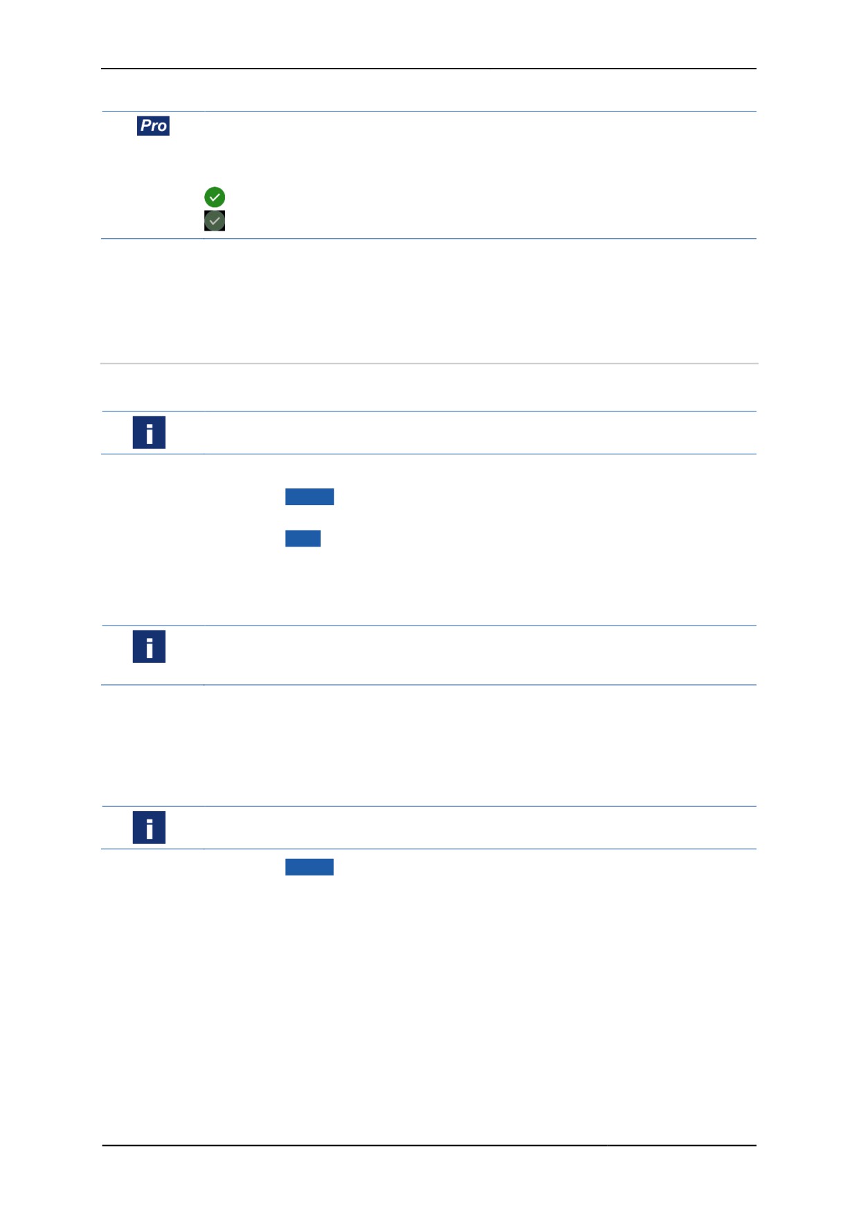
The system allows parallel use of several active remote connections (multi-session
connections). Whilst one remote connection is displayed on the screen, the other
connection stays active in the background. These connections are marked as follows
in the address book:
connection active in the foreground
connection active in the background
Activate the parallel use of several remote connections in the Settings menu under
the Connections menu item. See also:
• Allowing multiple simultaneous connections
3.2.2
Set-up of RDP connections
You will need the IP address or the name of the server for the configuration. These
are stored in the system properties of the server.
For RDP connections, remote access must be explicitly permitted in the server's
system properties. The remote access must be configured for the user.
1. Open the Address Book register.
2. Click on
+ Add .
¾ A new address book entry is created.
3. Click on Edit .
4. In Connection Settings, via the drop-down field Type, select "RDP".
5. Under Name, enter the name of the connection.
6. Under Server Address, enter the IP address or the name of the server.
To ensure automatic access to the connected server you have to enter the correct
logon data. Please note that a domain name may have to be used together with the
user name.
7. Under User Name and Password, enter the logon data of the server.
8. If you want to be able to call up the remote connection via the keyboard, use
Hotkey to specify a hotkey.
9. Click on Show on to select the display option.
10. Specify the minimum user role required for the manual set-up of the connection.
If a user does not have the required authority to set up the connection, this connection
is greyed out in the address book.
11. Click on Apply to set up the connection.
9 The connection is shown in the address book.
21
Remote HMI
Manual
3.2.3
Set-up of the VNC connection.
A VNC client is pre-installed on the Thin Client. The VNC service must also be
installed on the server. Administrator authority is required on the Thin Client and the
server for the installation.
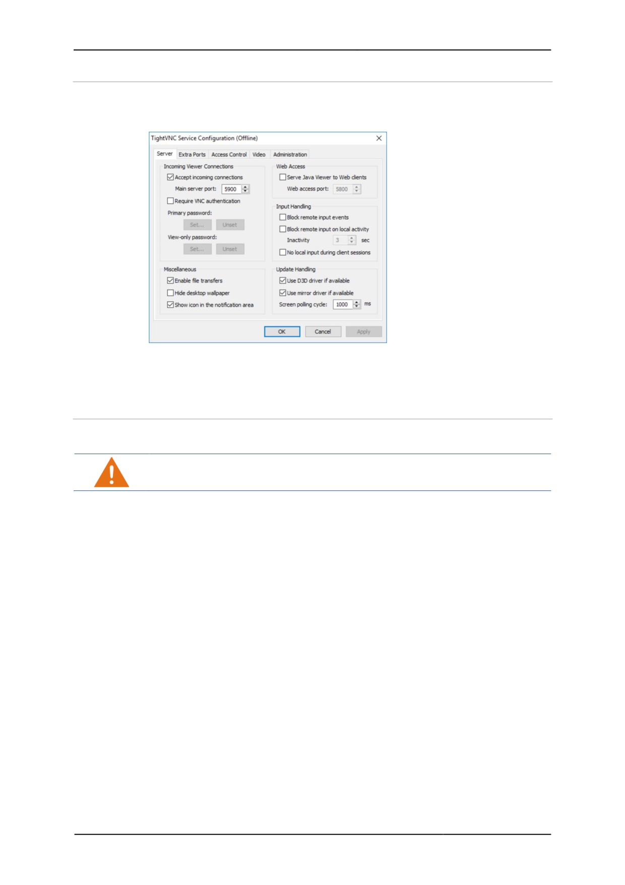
Set-up menu of the pre-installed VNC service
To set up the connection you require the IP address of the VNC server and,
depending on the configuration, the VNC password.
3.2.3.1
Preparation of host for VNC connection
The process varies according to which VNC service is used. For more information,
please refer to the documentation provided by the VNC service manufacturer.
This process requires Administrator authority.
1. Make sure that the Thin Client can contact the host. If both are part of the same
network, this will be the case.
2. Make sure the VNC service is installed and activated on the host (see Activating
VNC server system on the host).
3. If the network connection is protected via a firewall you need to configure this
firewall. Permit network communication via the port where the VNC service is
ready to receive (5900 as a standard).
4. If the network connection is protected via a router, you need to configure this
router. For the transfer of network communication, specify every configured port
where the VNC service is ready to receive (5900 as a standard).
5. Check whether the VNC service is working properly and whether it accepts
incoming connections.
9 The host is ready.
22
Remote HMI
Manual
3.2.3.2
Preparation of Thin Client
The process varies according to which VNC service is used. For more information,
please refer to the documentation provided by the VNC service manufacturer.
This process requires Administrator authority.
1. Make sure that the Thin Client can contact the host. If both are part of the same
network, this will be the case.
2. If the VNC connection of the Thin Client is protected via a proxy server you have
to specify the proxy server in the VNC viewer.
9 The Thin Client is ready
3.2.3.3
Set-up of the Thin Client
If the port number of the VNC server is different from the standard port, the IP address
needs to be extended to include the port number, for example: 192.168.1.23:5901
1. Open the Address Book register.
2. Click on
+Add .
¾ A new address book entry is created.
3. Click on Edit .
4. In the Connection Settings, select "VNC" from the Type drop-down field.
5. Under Name, enter the name of the connection.
6. Under Server Address, enter the IP address of the server.
To ensure automatic access to the connected server you have to enter the correct
logon data.
7. Enter the logon data of the server.
8. If you want to be able to call up the remote connection via the keyboard, use
Hotkey to specify a hotkey.
9. Under Show on, select the display option.
10. Specify the minimum user role required for the manual set-up of the connection.
If a user does not have the required authority to set up the connection, this connection
is greyed out in the address book.
11. Click on Apply to set up the connection.
9 The connection is shown in the address book.
3.2.4
Set-up of KVM-over-IP connection
To establish a connection you require a VNC service which runs on the KVM box.
To set up the connection you require the IP address of the VNC server and,
depending on the configuration, the VNC password.
1. Open the Address Book menu.
2. Click on
+Add .
¾ A new address book entry is created.
3. Open the address book entry.
4. In the Connection Settings, select "KVM over IP" from the Type drop-down
field.
5. Enter the name of the connection in the Name field.
6. Enter the IP address of the KVM box in the Server Address field.
7. Under User Name and Password, enter the logon data of the KVM box.
23
Remote HMI
Manual
8. If you want to be able to call up the remote connection via the keyboard, use
Hotkey to specify a hotkey.
9. Use Show on to select the display option.
10. Specify the minimum user role required for the manual set-up of the connection.
If a user does not have the required authority to set up the connection, this connection
is greyed out in the address book.
11. Click on Apply to set up the connection.
9 The connection is shown in the address book.
3.3
Test of remote connection
You can test the remote connection in the address book.
Starting a remote connection
• Close the settings window of the remote connection.
• In the list, click on the remote connection you want to test.
• If you have configured a hotkey, check whether the remote connection also starts
via the hotkey.
9 Once a connection has been established, the symbol changes to .
Remote connection does not start
¾ If no connection has been established, the symbol changes to . The
system will issue an error message.
• Check whether the settings are correct.
If the host is available, try to narrow down the source of the problem with the following
checks:
Check RDP connection
1. Check in the server's system settings whether a RDP connection is permitted.
2. Check whether the Thin Client is listed at the server as a user with the required
user rights.
Check VNC connection
1. Check whether the VNC service is configured correctly.
2. Check whether the port number has been entered correctly.
Check KVM-over-IP connection
1. Check the configuration of the KVM box.
2. Check whether the port number has been entered correctly.
3.4
Activation of user roles
Activation of user roles
1. Open the Access Control menu.
2. Under Main, activate the 3-tier access control.
3. Activate Limit Operator access to Dashboard to hide the dashboard's
register bar from the operator.
¾ Operators can only see the dashboard data.
4. Under Login Passwords, enter different passwords for the "Engineer" and
"Admin" user roles.
24
Remote HMI
Manual
5. Repeat the passwords. If the passwords are incorrect, the system will issue an
error message.
6. Click on Apply to accept the settings.
9 Users with roles "Engineer" and "Admin" have to logon with their passwords.
3.5
Further configuration options
Protection
Use this menu to activate the firewall, the virus protection and the UWF filter and to
block the use of USB devices. See also:
• Activate firewall and virus protection
• Activating write protection for the SSD
• Activating the USB lockdown
• Configuration of system behaviour during restart
Display
Use this menu to adjust the display on the screen or to activate a screen saver. See
also:
• Adjusting display settings
• Adjusting multi-display settingsif two displays are connected to the Thin Client.
For Pro licence users
To enable users to access the applications on the Thin Client, you have to install the
applications and add a link in the Applications register. See also:
• Adding apps
25
Remote HMI
Manual
4
First steps for the operator
4.1
Start menu
The system will start with the following screen.
Opening the dashboard
1. On the start screen, click on the F8 Menu button, press the [F8] function key or
press the keyboard icon for several seconds.
¾ The minimised dashboard will pop up.
Navigation elements
opens the expanded dashboard
minimises the dashboard
navigates to register or menu
4.2
Using the virtual keyboard
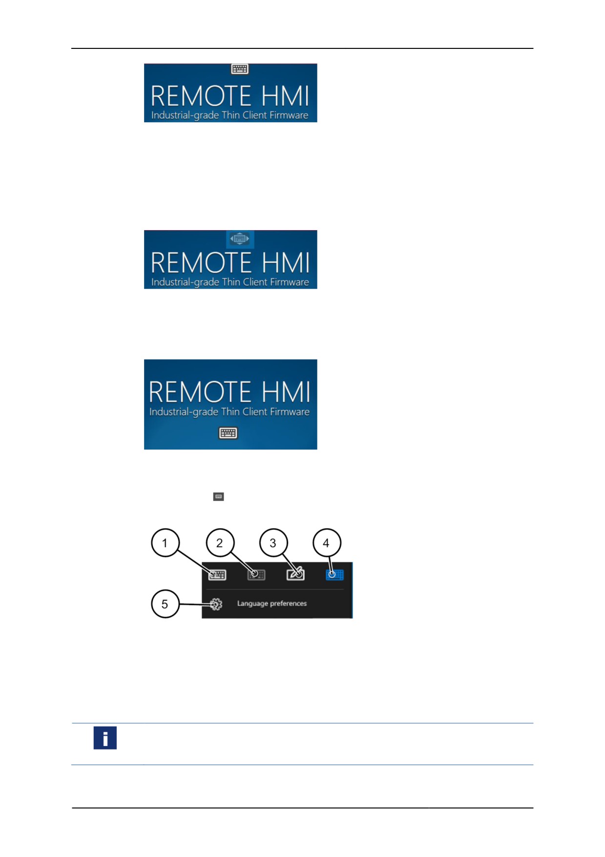
• Touch the keyboard icon to open the keyboard.
¾ When the configuration menu is active, the keyboard icon is located above the
menu bar.
26
Remote HMI
Manual
¾ If a remote connection is active, the keyboard icon is located at the top right
edge of the screen.
Moving the virtual keyboard icon
• Move the cursor to the keyboard icon.
• With the left mouse key, click on the keyboard icon and hold for a few seconds
until the cursor changes to the symbol for object moving.
The keyboard icon in "object moving" mode
• Move the keyboard icon to the desired position.
9 The keyboard position is saved. When the remote connection is next started
up, the keyboard will be positioned there.
Adjustment of keyboard properties
• Touch the keyboard icon to open the keyboard.
• Touch the
key.
¾ The keyboard settings will pop up. You have the following options:
1
Displays keyboard without control keys
2
Displays keyboard for cursor control and positioning, as well as special keys
3
Opens handwriting recognition
4
Displays keyboard with all control keys
5
Opens language setting for the keyboard
Use the Windows key in combination with another key to use a function of the
Windows operating system. A double-click of the Windows key will open the start
menu.
27
Remote HMI
Manual
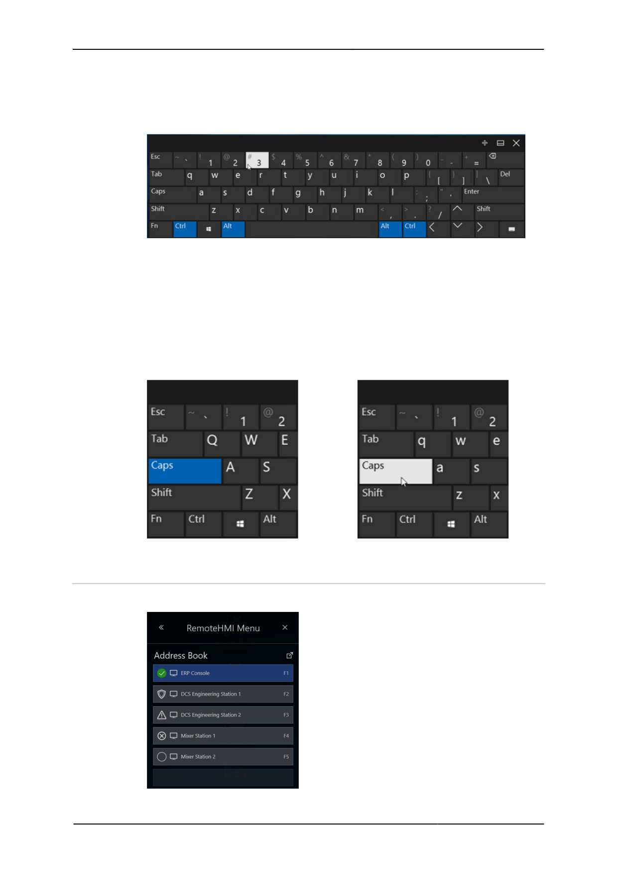
Using the Shift, Ctrl, Alt und Windows control keys
• First touch the control key.
¾ The key changes colour.
• Touch the next key of the key combination.
9 Once the key combination is complete, the function is executed and the colour
changes back.
Using the Caps Lock key (Caps)
1. First touch the Caps Lock key.
¾ The key changes colour and stays that way.
2. Touch the next key of the key combination.
3. Touch the Caps Lock key again to deactivate it.
9 The colour of the key reverts to its original.
Activated Caps Lock key
Deactivated Caps Lock key.
4.3
Starting a remote connection
The remote connections can be selected from the address book.
28
Remote HMI
Manual
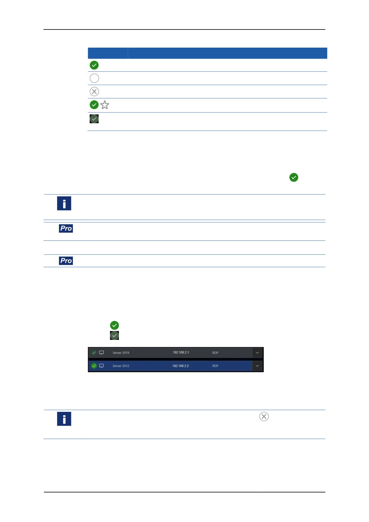
Status of the remote connection
Symbol
Meaning
connected
not connected
connection not possible
default, will be connected automatically during start-up
connected, parallel remote connection, active in the background (multi-
session connections require a Pro licence)
Starting / changing a remote connection
1. In the Dashboard, click on the remote connection you want to activate.
2. If a hotkey or a function key has been specified in the Address Book you can
also start the remote connection via the keyboard.
9 Once a connection has been established, the symbol changes to . The
remote connection that was previously active will be deactivated.
If an input window pops up requesting user name and password you need to enter
both to be able to access the server. Contact your network administrator for the user
name and password.
If the parallel use of several remote connections has been activated you can switch
between the connected PCs. Both connections remain active.
Using multiple remote connections simultaneously
Requires a Pro licence.
1. In the Dashboard, click on the remote connection which you also want to
activate.
2. If a hotkey or a function key has been specified in the Address Book, you can
also start the remote connection via the keyboard.
¾ Once the connection to the other PC has been established, the connections
are displayed as follows:
connection active in the foreground
connection active in the background
3. Click on the connection you want in order to change the display.
9 Both connections remain active.
Remote connection does not start
If no connection has been established, the symbol changes to . The system will
issue an error message. Make a note of its contents as they will be needed for fixing
the problem.
• Get in touch with an Admin or an Engineer to have the problem fixed.
• Inform them of the contents of the error message.
29
Remote HMI
Manual
4.4
Using the dashboard settings
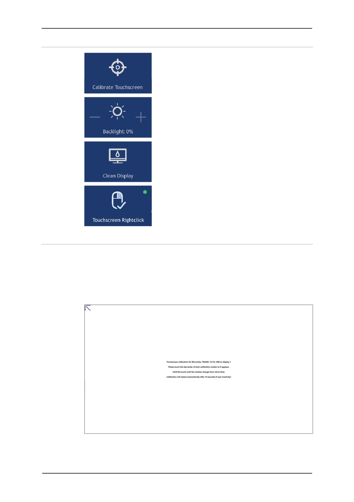
Button to start the touchscreen calibration. If two
touchscreens are connected you can calibrate them
separately.
Button to adjust the display backlight.
Button to deactivate the display touch function for 30
seconds Inadvertent activation of buttons during
cleaning is thus impossible.
Button to simulate a right mouse click on the
touchscreen, for example to call up the context menu
of applications.
4.4.1
Calibrating the touchscreen
The touchscreen is calibrated via defined calibration points (top left, centre left, bottom
left, top centre, centre centre, bottom centre, top right, centre right, bottom right).
These are shown one after the other during calibration.
Calibrating a touchscreen
1. Tap on Calibrate Touchscreen to start the calibration process.
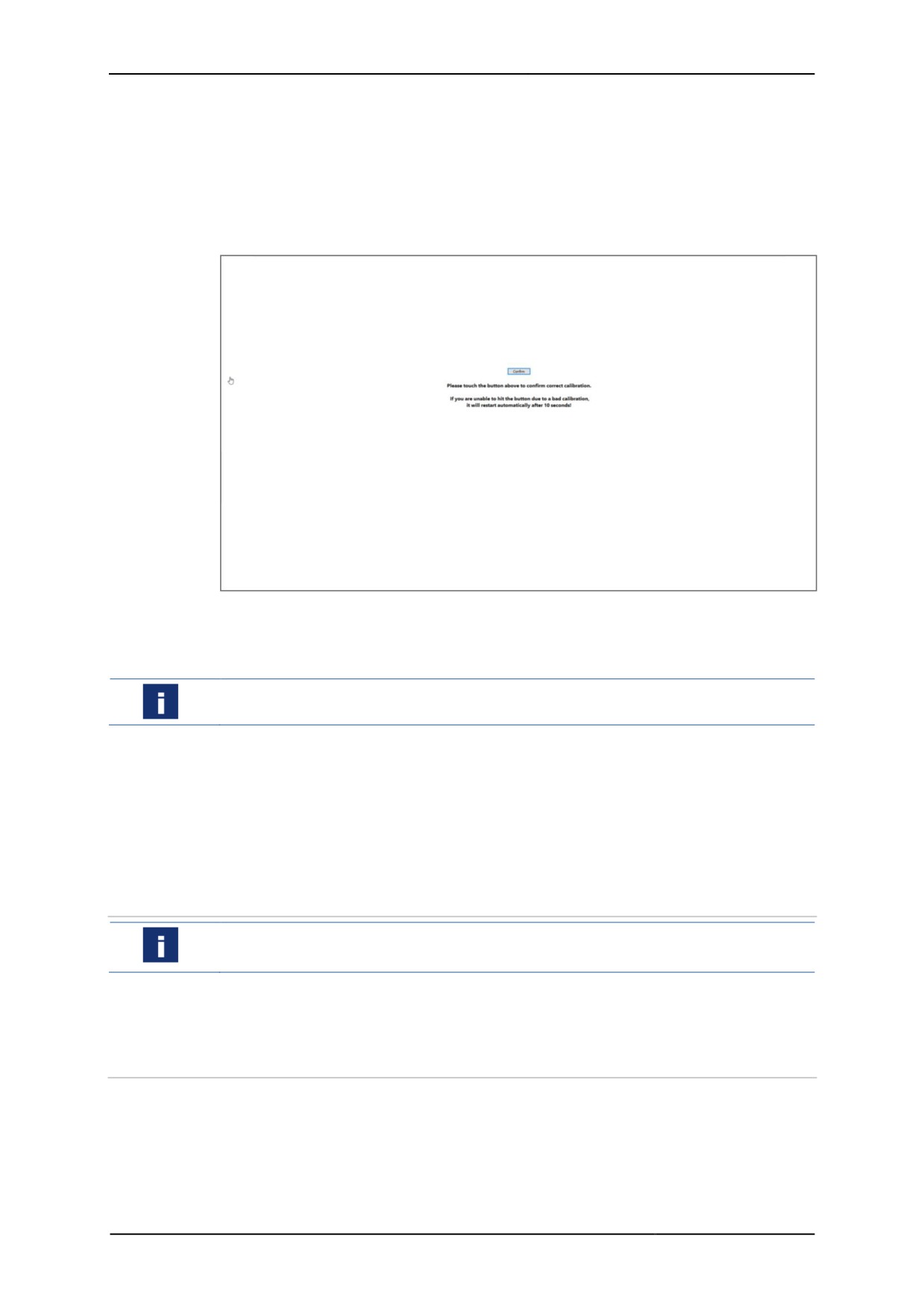
¾ The display becomes monochrome and the first calibration point pops up.
30
Remote HMI
Manual
1. Tap on this calibration point and keep it pressed until its colour turns from blue to
red and back to blue again (visual feedback).
¾ The next calibration point pops up.
2. Repeat step one for every calibration point. Make sure you hit the points exactly.
¾ After the last calibration point has been dealt with, the following message will
pop up:
Please touch the button above to confirm correct calibration.
1. Confirm the calibration by tapping on Confirm.
9 Once the touchscreen has been calibrated, the display returns to the
RemoteHMI menu.
If the calibration has not been performed correctly it cannot be confirmed. The
calibration process will re-start automatically after 10 seconds.
If two touchscreens are connected, the button is split. You can calibrate each
touchscreen separately.
1. The left hand side of the Calibrate Touchscreen 1 button starts the
calibration of the first touchscreen.
2. The right hand side of the Calibrate Touchscreen 2 button starts the
calibration of the second touchscreen.
4.4.2
Adjusting display brightness
To increase the service life of the backlight we recommend you activate the
Backlight Auto Dimming function (see Display settings).
• Tap on + to increase display brightness.
• Tap on - to reduce display brightness.
4.4.3
Opening the context menu at the touchscreen
Tapping on the touchscreen simulates a click with the left mouse key. If you want to
open the context menu of applications you have to simulate a right mouse key click.
31
Remote HMI
Manual
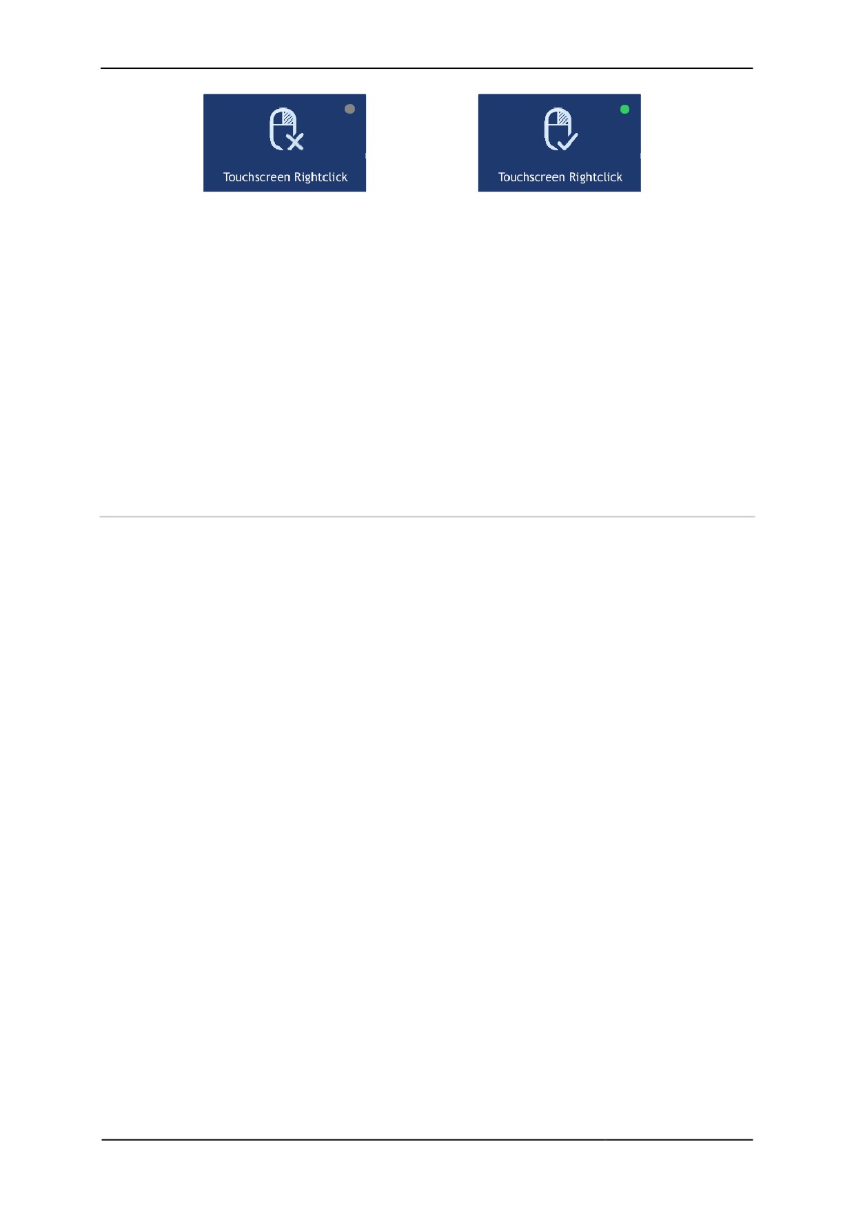
Right mouse key deactivated
Right mouse key activated
Calling up the context menu of an application
1. Tap on Touchscreen Rightclick to activate the functions of the right mouse
key.
2. Place your finger or pen on the position where you want to click with the right
mouse key. A circle appears around the point of touch.
3. Keep your finger or pen on the screen until the circle is complete.
4. Remove your finger or pen once the circle is closed.
9 The context menu pops up.
If no context menu pops up, no context menu is available for the position you clicked
on.
If you remove your finger or pen before the circle has closed the right mouse key click
is aborted.
4.4.4
Cleaning the touchscreen
• Tap on Clean Display to deactivate the touch functions for 30 seconds.
• Clean the touchscreen.
32
Remote HMI
Manual
4.5
Starting applications
Requires a Pro licence.
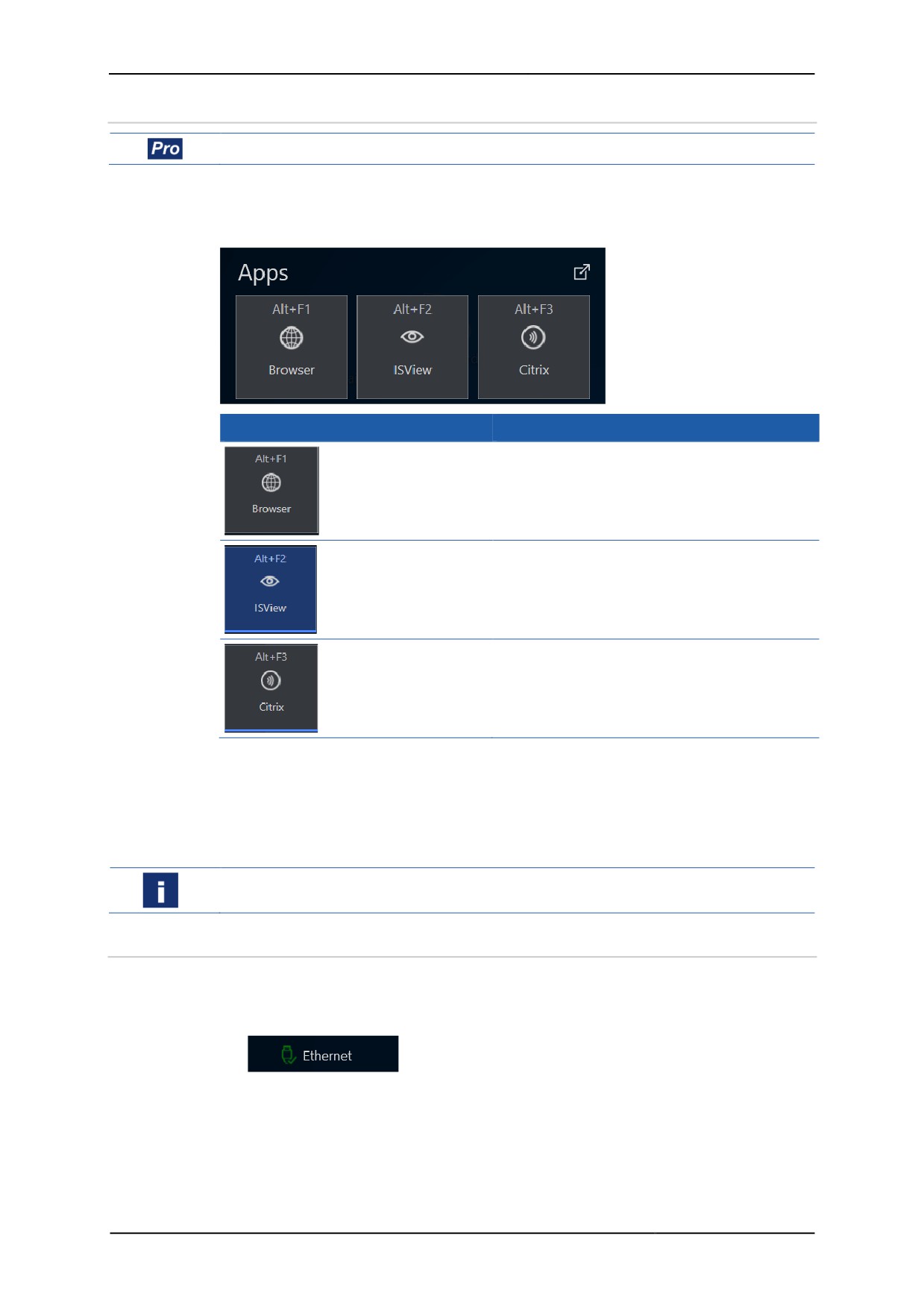
Applications can only be used with a Pro licence of the firmware.
Once applications (apps) have been set up, they are shown as buttons. More than one
app can be started. The status of the app is shown.
Display
Meaning
inactive app
active app
app running in the background
Calling up an app
1. On the Dashboard, click on the app you want to use.
2. If a hotkey or function key has been allocated to the button you can also start the
app via the keyboard.
9 The app is started.
If you lack the required access authority for the app, contact your administrator.
4.6
Calling up the status of the Ethernet connection
Calling up the status of the Ethernet connection
1. Open the Dashboard.
2. In the bar at the bottom, click on the button for the Ethernet connection.
33
Remote HMI
Manual
¾ The status information will be displayed.
3. Alternatively, use
to open the expanded dashboard.
¾ All system information will be displayed on the right hand side.
4.7
Using the multi-display mode
If two displays are connected to the Thin Client, the following types of display are
possible:
• Both displays show the same content.
• Both displays show different content. What is shown on the main display is
expanded by the second display.
34
Remote HMI
Manual
5
Address book
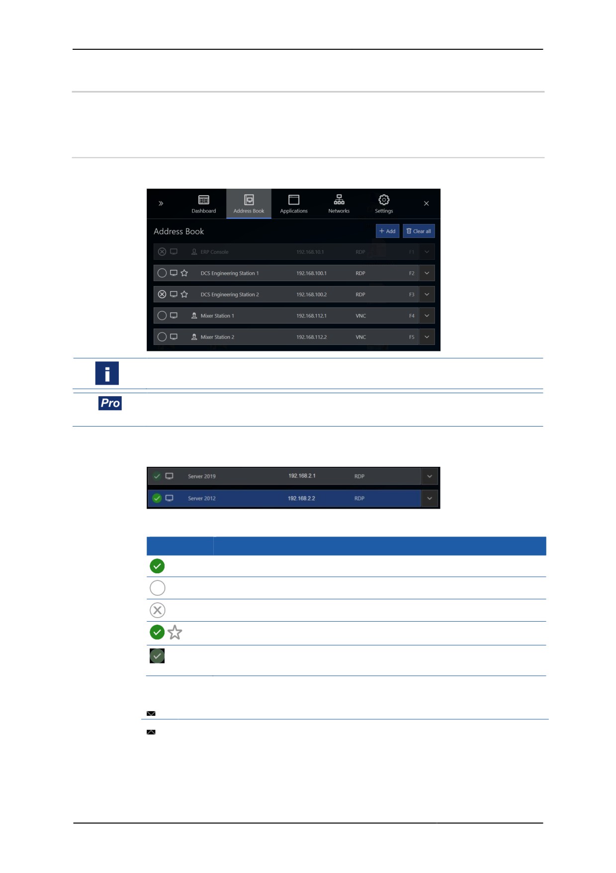
Use the Address Book register to call up or manage configured remote connections
or create new remote connections.
5.1
Address book options
The Address Book register lists all configured remote connections.
If a connection in the address book is greyed out, the user's authority level is too low
to access it.
The simultaneous use of multiple remote connections (multi-session connection)
requires the Pro licence and must be activated in the Connections menu.
If the parallel use of several remote connections has been activated, the connections
will be displayed as follows:
Status of the remote connection
Symbol
Meaning
connected
not connected
connection not possible
default, will be connected automatically during start-up
connected, parallel remote connection, active in the background (multi-
session connections require a Pro licence)
Navigation elements
opens an item in the list
closes an item in the list
35
Remote HMI
Manual
Address book functions
The available edit functions or buttons depend on the sub-menu.
Add
Adds a new entry.
Clear all
Deletes all entries in the list
Edit
Opens the highlighted entry for editing
Copies the highlighted entry and opens the
Copy
copy for editing
Delete
Deletes the highlighted entry
Manage
Navigates back to the list level
Apply
Applies input
Revert
Rejects input
Moves the highlighted entry one place up in
Up
the list
Moves the highlighted entry one place down
Down
in the list
Opens the dialogue for editing the remote
Edit profile
profile
Hotkey for calling up remote connections
You can call up the remote connection via the keyboard if you have specified a hotkey
under the Hotkey function. Three keys can be specified.
First key
Second key
Third key
[Shift]
[Ctrl]
none
[Ctrl]
[Alt]
[F1] ... [F12]
The Ctrl key must not be selected twice.
5.2
Set-up of remote connections
Automatic logon at the server
The automatic logon at the server can be configured in the settings of the remote
connection. For this you need the user ID and the password for the server.
Only users with authority for remote access to the server can log on to the server.
Check the user authority at the server or the KVM box.
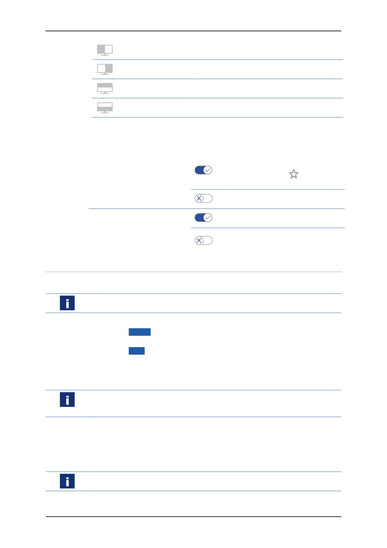
Display position of the server screen
Different parts of the server screen can be displayed. You can configure the display
via Show on when creating the remote connection.
The following display options are available:
Symbol Name
Meaning
Full display
shows the full screen
36
Remote HMI
Manual
Scales the remote screen content and displays it
Left display half
on the left hand side
Scales the remote screen content and displays it
Right display half
on the right hand side
Scales the remote screen content and displays it at
Upper display half
the top half
Scales the remote screen content and displays it at
Lower display half
the bottom half.
Behaviour of firmware when connection is lost
You can configure how the remote connection behaves during a system startup or
when it is lost, as follows:
Auto connect on system
Automatically establishes a
connection during system startup, is
startup
On
represented by the
symbol in the
address book entry
During a system startup the dial-up
Off
must be started manually
Auto reconnect on
Automatically reconnects after the
On
connection has been lost
connection loss
After the connection has been lost,
Off
the dial-up must be started
automatically
5.2.1
Set-up of RDP connections
You will need the IP address or the name of the server for the configuration. These
are stored in the system properties of the server.
For RDP connections, remote access must be explicitly permitted in the server's
system properties. The remote access must be configured for the user.
1. Open the Address Book register.
2. Click on
+ Add .
¾ A new address book entry is created.
3. Click on Edit .
4. In Connection Settings, via the drop-down field Type, select "RDP".
5. Under Name, enter the name of the connection.
6. Under Server Address, enter the IP address or the name of the server.
To ensure automatic access to the connected server you have to enter the correct
logon data. Please note that a domain name may have to be used together with the
user name.
7. Under User Name and Password, enter the logon data of the server.
8. If you want to be able to call up the remote connection via the keyboard, use
Hotkey to specify a hotkey.
9. Click on Show on to select the display option.
10. Specify the minimum user role required for the manual set-up of the connection.
If a user does not have the required authority to set up the connection, this connection
is greyed out in the address book.
37
///////////////////////////////////////