Cisco IE 2000 Switch Hardware Installation Guide (2016) - page 3
Warning: Do not connect or disconnect cables to the ports while power is applied to the switch or any device on
the network because an electrical arc can occur. This could cause an explosion in hazardous location installations.
Be sure that power is removed from the switch and cannot be accidentally be turned on, or verify that the area is
nonhazardous before proceeding. Statement 1070
Caution: Do not remove the rubber plugs from the SFP module port or the rubber caps from the fiber-optic cable until
you are ready to connect the cable. The plugs and caps protect the SFP module ports and cables from contamination
and ambient light.
Caution: Before connecting to the SFP module, be sure that you understand the port and cabling guidelines in Preparing
for Installation, page 29. See Cable and Connectors, page 87 for information about the LC on the SFP module.
Caution: To prevent ESD damage, follow standard board and component handling procedures.
Connecting to a Fiber Optic SFP Module
To connect a fiber-optic cable to an SFP module, follow these steps:
1. Remove the rubber plugs from the module port and fiber-optic cable, and store them for future use.
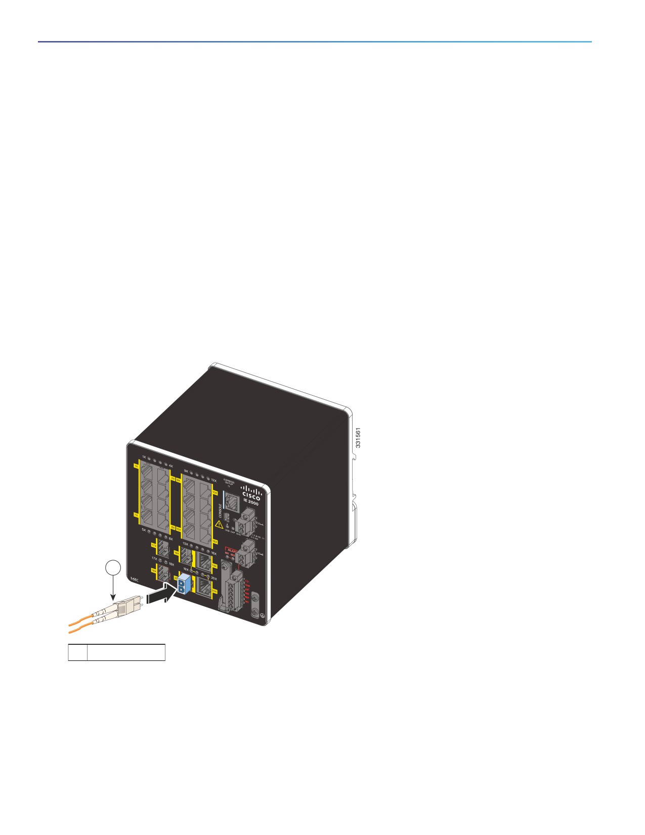
2. Insert one end of the fiber-optic cable into the SFP module port. See Figure 45 on page 70.
Figure 45
Connecting to a Fiber-Optic SFP Module Port
1
1
LC connector
3. Insert the other cable end into a fiber-optic receptacle on a target device.
4. Observe the port status LED:
— The LED turns green when the switch and the target device have an established link.
— The LED turns amber while the STP discovers the network topology and searches for loops. This process takes
about 30 seconds, and then the port LED turns green.
70
— If the LED is off, the target device might not be turned on, there might be a cable problem, or there might be a
problem with the adapter installed in the target device. See Troubleshooting, page 75 for solutions to cabling
problems.
5. If necessary, reconfigure and restart the switch or the target device.
Connecting to a 1000BASE-T SFP Module
Follow these steps to connect a CAT5 cable to a 1000BASE-T SFP module:
1. When connecting to servers, workstations, and routers, insert a four twisted-pair, straight-through cable in the
RJ-45 connector. When connecting to switches or repeaters, insert a four twisted-pair, crossover cable.
When connecting to a 1000BASE-T device, use a four twisted-pair CAT5 cable.
2. Insert the other cable end in an RJ-45 connector on a target device.
3. Observe the port status LED.
— The LED turns green when the switch and the target device have an established link.
— The LED turns amber while the STP discovers the network topology and searches for loops. This process takes
about 30 seconds, and then the port LED turns green.
— If the LED is off, the target device might not be turned on, there might be a cable problem, or there might be
problem with the adapter installed in the target device. See Troubleshooting, page 75 for solutions to cabling
problems.
4. If necessary, reconfigure and restart the switch or target device.
Connecting to a Dual-Purpose Port
The dual-purpose port is a single port with two interfaces, one for an RJ-45 cable and another for an SFP module. Only
one interface can be active at a time. If both interfaces are connected, the SFP module has priority. For more information
about dual-purpose ports, see Power Connectors, page 17.
Warning: Class 1 laser product. Statement 1008
Caution: Do not remove the rubber plugs from the SFP module port or the rubber caps from the fiber-optic cable until
you are ready to connect the cable. The plugs and caps protect the SFP module ports and cables from contamination
and ambient light.
Caution: Before connecting to the SFP module, be sure that you understand the port and cabling stipulations in Preparing
for Installation, page 29. See Cable and Connectors, page 87 for information about the LC on the SFP module.
To connect to a dual-purpose port, follow these steps:
1. Connect an RJ-45 connector to the 10/100/1000 port, or install an SFP module into the SFP module slot, and
connect a cable to the SFP module port. See Figure 46 on page 72.
For more information about RJ-45 connections, SFP modules, and optical connections, see Connecting to 10/100
and 10/100/1000 Ports, page 64, Installing and Removing SFP Modules, page 66, and Connecting to SFP Modules,
page 69.
71
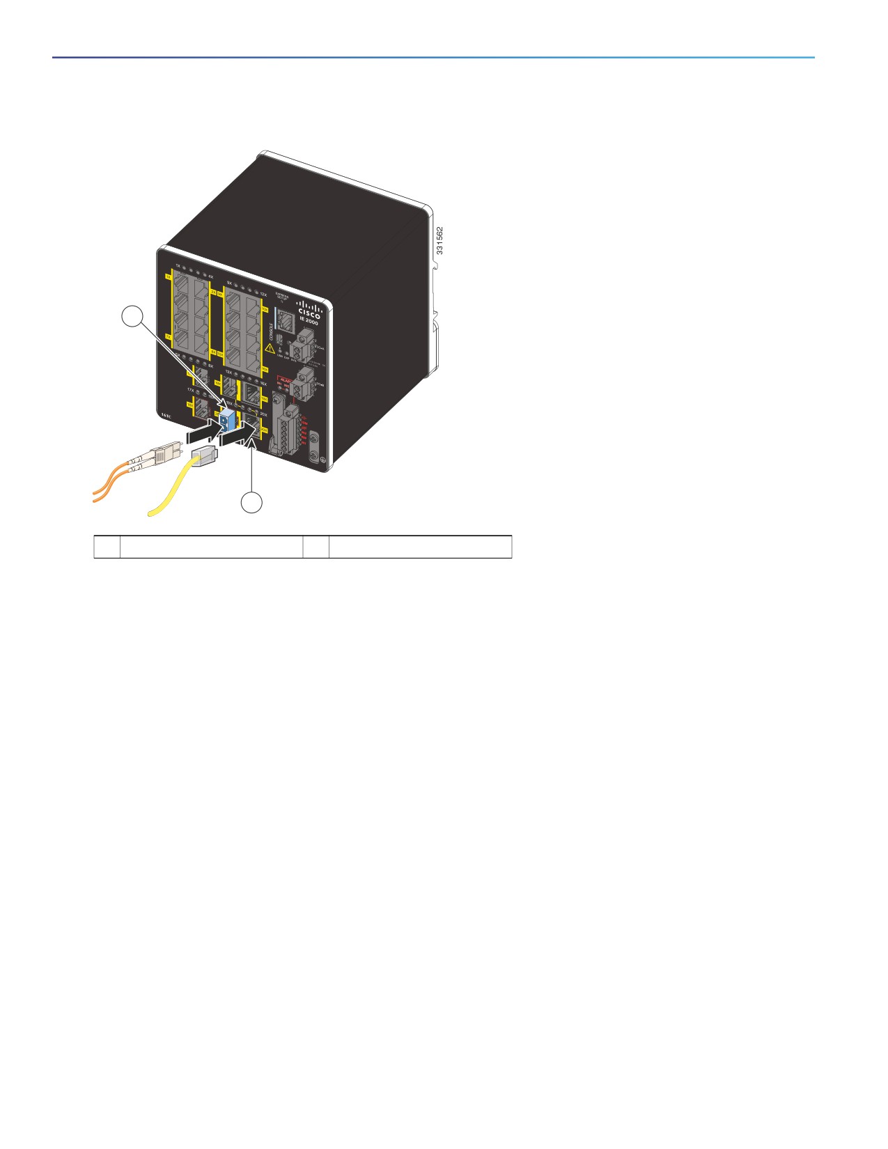
Figure 46
Connecting to a Dual-Purpose Port
1
2
1
LC connector (optical)
2
RJ-45 connector (copper)
2. Connect the other end of the cable to the other device.
By default, the switch detects whether an RJ-45 connector or SFP module is connected to a dual-purpose port and
configures the port accordingly. You can change this setting and configure the port to recognize only an RJ-45 connector
or only an SFP module by using the media type interface configuration command. For more information, see the Cisco
IE 2000 Switch Command Reference.
Verifying Switch Operation
Before installing the switch in its final location, power on the switch, and verify that the switch powers up in boot fast
style. The boot fast sequence allows the switch to boot up in less than 60 seconds.
Where to Go Next
If the default configuration is satisfactory, the switch does not need further configuration. You can use any of these
management options to change the default configuration:
Start Device Manager, which is in the switch memory, to manage individual and standalone switches. This is an
easy-to-use web interface that offers quick configuration and monitoring. You can access Device Manager from
anywhere in your network through a web browser. For more information, see Running Express Setup, page 97 and
the Device Manager online help.
Start the Cisco Network Assistant application, which is described in the Getting Started with Cisco Network Assistant
guide. Using the GUI, you can configure and monitor a switch cluster or an individual switch.
Use the CLI to configure the switch as an individual switch from the console. See the Command Reference on
Cisco.com for information about using the CLI.
Start an SNMP application such as the CiscoView application.
72
Start the Common Industrial Protocol (CIP) management tool. You can manage an entire industrial automation system
with the CIP-based tools.
73
74
Troubleshooting
This chapter provides these topics for troubleshooting problems:
Diagnosing Problems, page 75
How to Recover Passwords, page 78
Finding the Switch Serial Number, page 78
Diagnosing Problems
The switch LEDs provide troubleshooting information about the switch. They show boot fast failures, port-connectivity
problems, and overall switch performance. You can also get statistics from Device Manager, the CLI, or an SNMP
workstation. See the Cisco IE 2000 Switch Software Configuration Guide, the Cisco IE 2000 Switch Command Reference
on Cisco.com, or the documentation that came with your SNMP application for details.
Switch Boot Fast
See Verifying Switch Operation, page 72 for information on boot fast.
Note: Boot fast failures are usually fatal. Contact your Cisco TAC representative if your switch does not successfully
complete boot fast.
Note: You can disable the boot fast and run POST by using the Cisco IOS CLI, see the Cisco IE 2000 Switch Software
Configuration Guide and the Cisco IE 2000 Switch Command Reference for more information.
Switch LEDs
Look at the port LEDs information when troubleshooting the switch. See LEDs, page 20 for a description of the LED colors
and their meanings.
Switch Connections
Bad or Damaged Cable
Always examine the cable for marginal damage or failure. A cable might be just good enough to connect at the physical
layer, but it could corrupt packets as a result of subtle damage to the wiring or connectors. You can identify this problem
because the port has many packet errors or it constantly flaps (loses and regains link).
Exchange the copper or fiber-optic cable with a known good cable.
Look for broken or missing pins on cable connectors.
Rule out any bad patch panel connections or media converters between the source and the destination. If possible,
bypass the patch panel, or eliminate media converters (fiber-optic-to-copper).
Try the cable in another port to see if the problem follows the cable.
75
Ethernet and Fiber-Optic Cables
Ensure that you have the correct cable:
For Ethernet, use Category 3 copper cable for 10 Mb/s UTP connections. Use either CAT5, CAT5e, or CAT6 UTP for
10/100, 10/100/1000 Mb/s, and PoE connections.
Verify that you have the correct fiber-optic cable for the distance and port type. Make sure that the connected device
ports match and use the same type encoding, optical frequency, and fiber type.
Determine if a copper crossover cable was used when a straight-through was required or the reverse. Enable
auto-MDIX on the switch, or replace the cable.
Link Status
Verify that both sides have a link. A broken wire or a shutdown port can cause one side to show a link even though the
other side does not have a link.
A port LED that is on does not guarantee that the cable is functional. It might have encountered physical stress, causing
it to function at a marginal level. If the port LED does not turn on:
Connect the cable from the switch to a known good device.
Make sure that both ends of the cable are connected to the correct ports.
Verify that both devices have power.
Verify that you are using the correct cable type. See Cables and Adapters, page 90 for information.
Look for loose connections. Sometimes a cable appears to be seated but is not. Disconnect the cable, and then
reconnect it.
10/100 and 10/100/1000 Port Connections
If a port appears to malfunction:
Verify the status of all ports by checking the LEDs. For more information, see Switch LEDs, page 75.
Use the show interfaces privileged EXEC command to see if the port is error-disabled, disabled, or shut down.
Reenable the port if necessary.
Verify the cable type. See Cable and Connectors, page 87.
SFP Module
Use only Cisco SFP modules. Each Cisco module has an internal serial EEPROM that is encoded with security information.
This encoding verifies that the module meets the requirements for the switch.
Inspect the SFP module. Exchange the suspect module with a known good module.
Verify that the module is supported on this platform. (The switch release notes on Cisco.com list the SFP modules
that the switch supports.)
Use the show interfaces privileged EXEC command to see if the port or module is error-disabled, disabled, or
shutdown. Reenable the port if needed.
Ensure that all fiber-optic connections are clean and securely connected.
76
Interface Settings
Verify that the interface is not disabled or powered off. If an interface is manually shut down on either side of the link, it
does not come up until you re-enable the interface. Use the show interfaces privileged EXEC command to see if the
interface is error-disabled, disabled, or shut down on either side of the connection. If needed, re-enable the interface.
Ping End Device
Ping from the directly connected switch first, and then work your way back port by port, interface by interface, trunk by
trunk, until you find the source of the connectivity issue. Make sure that each switch can identify the end device MAC
address in its Content-Addressable Memory (CAM) table.
Spanning Tree Loops
STP loops can cause serious performance issues that look like port or interface problems.
A unidirectional link can cause loops. It occurs when the traffic sent by the switch is received by the neighbor, but the
traffic from the neighbor is not received by the switch. A broken cable, other cabling problems, or a port issue can cause
this one-way communication.
You can enable UniDirectional Link Detection (UDLD) on the switch to help identify unidirectional link problems. For
information about enabling UDLD on the switch, see the “Understanding UDLD” section in the switch software
configuration guide on Cisco.com.
Switch Performance
Speed, Duplex, and Autonegotiation
Port statistics that show a large amount of alignment errors, frame check sequence (FCS), or late-collisions errors, might
mean a speed or duplex mismatch.
A common issue occurs when duplex and speed settings are mismatched between two switches, between a switch and
a router, or between the switch and a workstation or server. Mismatches can happen when manually setting the speed
and duplex or from autonegotiation issues between the two devices.
To maximize switch performance and to ensure a link, follow one of these guidelines when changing the duplex or the
speed settings.
Let both ports autonegotiate both speed and duplex.
Manually set the speed and duplex parameters for the interfaces on both ends of the connection.
If a remote device does not autonegotiate, use the same duplex settings on the two ports. The speed parameter
adjusts itself even if the connected port does not autonegotiate.
Autonegotiation and Network Interface Cards
Problems sometimes occur between the switch and third-party network interface cards (NICs). By default, the switch
ports and interfaces autonegotiate. Laptops or other devices are commonly set to autonegotiate, yet sometimes issues
occur.
To troubleshoot autonegotiation problems, try manually setting both sides of the connection. If this does not solve the
problem, there could be a problem with the firmware or software on the NIC. You can resolve this by upgrading the NIC
driver to the latest version.
77
Cabling Distance
If the port statistics show excessive FCS, late-collision, or alignment errors, verify that the cable distance from the switch
to the connected device meets the recommended guidelines. See Cables and Adapters, page 90.
Resetting the Switch
These are reasons why you might want to reset the switch to the factory default settings:
You installed the switch in your network and cannot connect to it because you assigned the wrong IP address.
You want to reset the password on the switch.
Note: Resetting the switch deletes the configuration and reboots the switch.
Caution: If you press the Express Setup button when you power on, the automatic boot sequence stops, and the switch
enters bootloader mode.
To reset the switch:
1. Press and hold the Express Setup button for about 10 seconds. The switch reboots. The system LED turns green
after the switch completes rebooting.
2. Press the Express Setup button again for 3 seconds. A switch 10/100 Ethernet port blinks green.
The switch now behaves like an unconfigured switch. You can configure the switch by using the CLI setup procedure
described in Configuring the Switch with the CLI-Based Setup Program, page 101. You can also configure the switch by
using Express Setup as described in Running Express Setup, page 97.
How to Recover Passwords
Password recovery is a feature that a system administrator can enable or disable. If password recovery is disabled, the
only way to recover from a lost or forgotten password is to clear the switch configuration entirely. For this procedure, see
How to Recover Passwords, page 78.
The Cisco IE 2000 Switch Software Configuration Guide provides details about enabling and disabling the password
recovery feature and the procedure for recovering passwords.
Finding the Switch Serial Number
If you contact Cisco Technical Assistance, you need to know the serial number of your switch. The serial number is on
the compliance label on the right-hand side of the switch. See Figure 47 on page 79. You can also use the show version
privileged EXEC command to obtain the switch serial number.
78
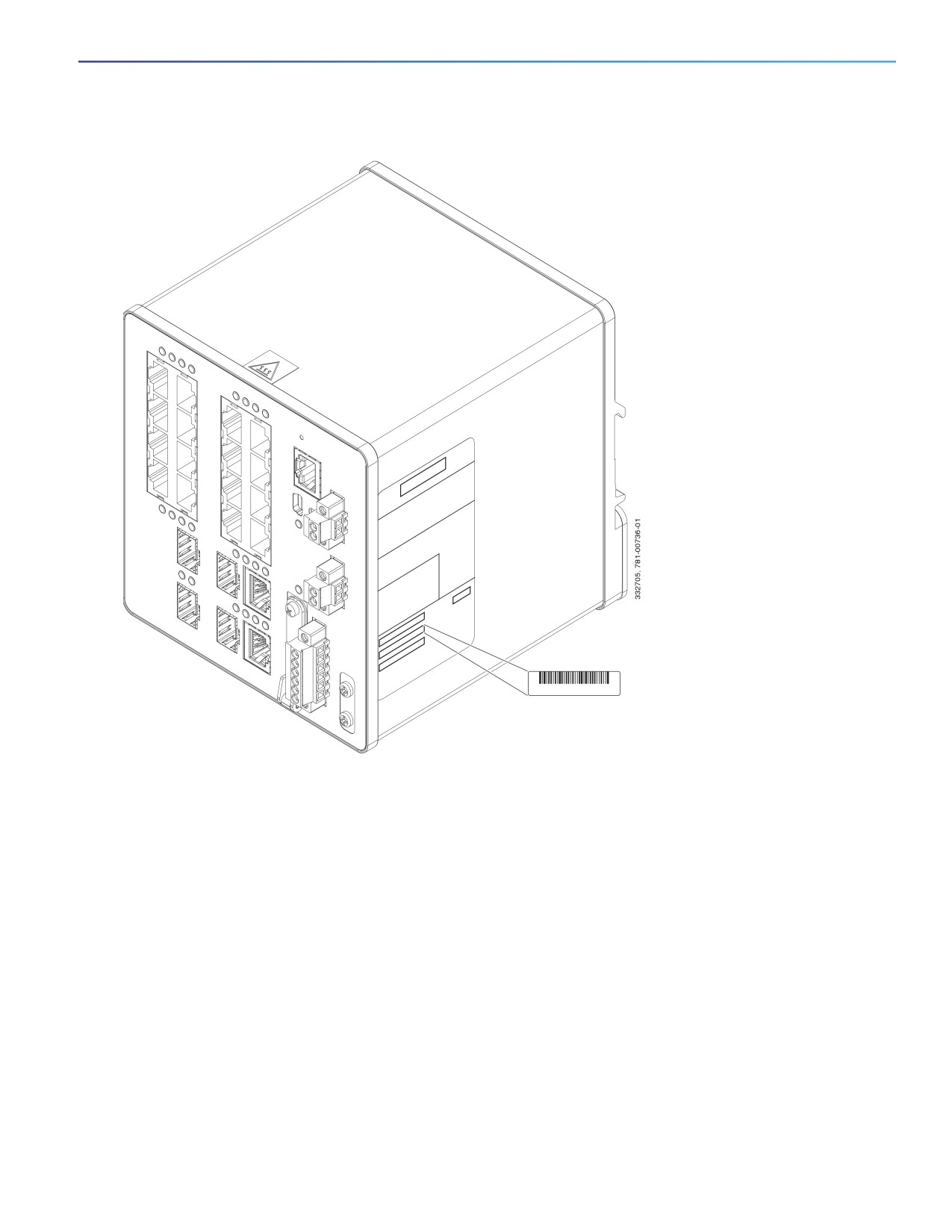
Figure 47
Serial Number Location for the Cisco IE-2000 Switches
SN: XXXNNNNXXXX
79
80
Technical Specifications
The most current technical specifications for the IE 2000 series switches can be found in the IE 2000 Data Sheet.
Additional specs and detail not in the Data Sheet, are found in this section.
Enclosure Specifications
Table 14 on page 81 lists enclosure specifications for the Cisco IE 2000 switches.
Table 14
Enclosure Specifications for the Cisco IE 2000 Switches
Industrial Automation and
Substation
Traffic Signal
Hazardous Locations
Enclosure
Sealed enclosures
Vented enclosures
Fan or blower-equipped
types
enclosures
For example: NEMA4, NEMA4X,
For example: NEMA1, IP20, and
NEMA12, NEMA13, IP54, and
IP21.
For example: NEMA TS-2.
IP66.
Note: The minimum airflow is 150
lfm1.
1 lfm = linear feet per minute.
Note:
The maximum ambient temperature of the IE-2000-16TC-G-X and IE-2000-16PTC-G-NX model is +65°C due to
its conformal coating feature. The maximum ambient temperature of the IE-2000-16PTC-G-L,
IE-2000-16PTC-G-E, and IE-2000-16PTC-G-NX model is +65°C if powering four PoE+ ports of 30 Watt each.
The safety certifications apply only to ambient temperatures under 140°F (60°C). However, the
Cisco IE 2000 switch can function in the substation and traffic signal installations under the environmental conditions
shown in Table 14 on page 81.
Alarm Ratings
Table 15 on page 81 lists the alarm ratings for the Cisco IE 2000 switches.
Table 15
Alarm Input and Output Ratings
Alarm Ratings
Specification
Alarm input electrical specification
No power required—open or closed state
detected.
Alarm output electrical specification
1.0 A @ 24 VDC or 0.5 A @ 48 VDC
81
Hazardous Locations Standards
Table 16 on page 82 lists the hazardous location standards for the Cisco IE 2000 switches.
Table 16
Hazardous Locations Standards
The following standards were used for the hazardous
Les normes suivantes ont été appliquées pour les
locations approvals and certifications:
approbations et les certifications dans le cadre
d'environnements dangereux :
ANSI/ASA 12.12.01-2013
ANSI/ASA 12.12.01-2013
CAN/CSA C22.2 No. 60079-0: 11
CAN/CSA C22.2 n° 60079-0 : 11
CAN/CSA C22.2 No. 60079-15:12
CAN/CSA C22.2 n° 60079-15 :12
CSA C22.2 No. 213-M1987
CSA C22.2 n° 213-M1987
EN 60079-0:2012
EN 60079-0:2012
EN 60079-15:2010
EN 60079-15:2010
IEC 60079-0 6th Edition
IEC 60079-0, 6e édition
IEC 60079-15 4th Edition
IEC 60079-15, 4e édition
UL 60079-0, 5th Ed, 2009-10-21
UL 60079-0, 5e éd., 21-10-2009
UL 60079-15, 3rd Ed, 2009-7-17
UL 60079-15, 3e éd., 17-07-2009
82
Cable and Connectors
Connector Specifications, page 87
Cables and Adapters, page 90
Connector Specifications
10/100 Ports, page 87
SFP Module Connectors, page 88
Dual-Purpose Ports, page 88
Alarm Port, page 89
10/100 Ports
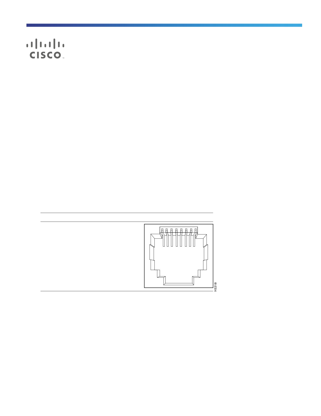
The 10/100 Ethernet ports on the switches use RJ-45 connectors. Figure
48 on page
87 shows the pinouts.
Figure 48
10/100 Port Pinouts
Pin
Label
1 2 3 4 5 6 7 8
1
RD+
2
RD-
3
TD+
4
NC
5
NC
6
TD-
7
NC
8
NC
For the three models of IE 2000 switch that support PoE, connector pins 3 and 6 supply +48/+54 VDC and pins 1 and 2
are the DC voltage return lines.
87
SFP Module Connectors
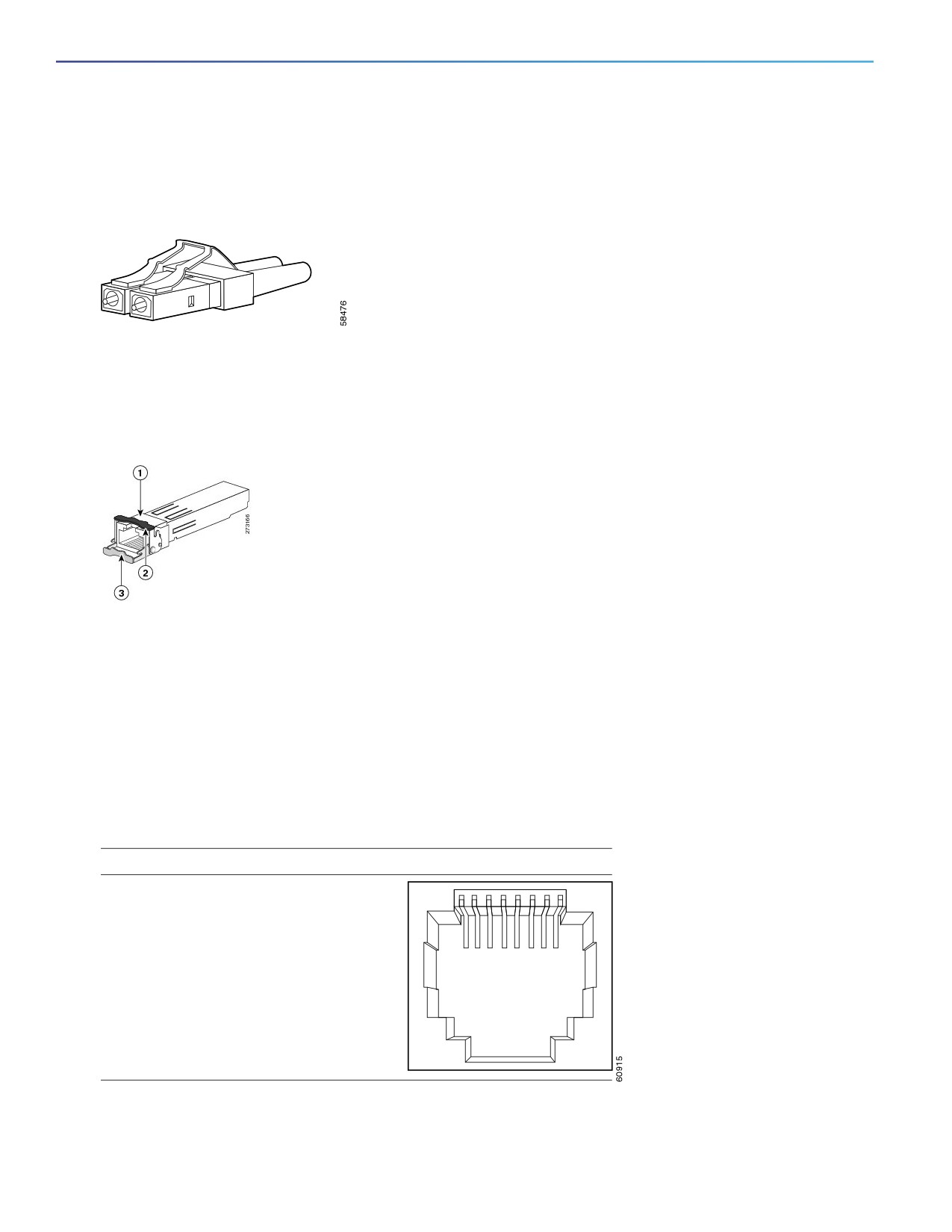
Figure 49 on page 88 shows the MT-RJ SFP module fiber-optic local connector (LC).
Figure 49
Fiber-Optic SFP Module LC Connector
Warning: Invisible laser radiation may be emitted from disconnected fibers or connectors. Do not stare into beams
or view directly with optical instruments. Statement 1051
Figure 50 on page 88 shows the 1000BASE-T SFP module RJ-45 connector.
Figure 50
1000BASE-T SFP Module Connector
1
RJ-45 connector
3
Bale-clasp latching mechanism in the open
(unlocked) position
2
Bale-clasp latching mechanism in the closed
(locked) position
Dual-Purpose Ports
The 10/100/1000 Ethernet ports on the dual-purpose ports use RJ-45 connectors. Figure 51 on page 88 shows the
pinouts.
Figure 51
10/100/1000 Port Pinouts
Pin
Label
1 2 3 4 5 6 7 8
1
TP0+
2
TP0-
3
TP1+
4
TP2+
5
TP2-
6
TP1-
7
TP3+
8
TP3-
88
Console Port
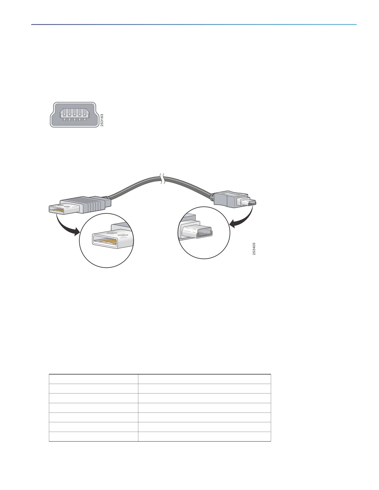
The switch has two console ports: a USB 5-pin mini-Type B port on the front panel (see Figure 52 on page 89) and an
RJ-45 console port on the rear panel.
Figure 52
USB Mini-Type B Port
The USB console port uses a USB Type A to 5-pin mini-Type B cable, shown in Figure 53 on page 89. The USB Type
A-to-USB mini-Type B cable is not supplied. You can order an accessory kit (part number 800-33434) that contains this
cable.
Figure 53
USB Type A-to-USB 5-Pin Mini-Type B Cable
The RJ-45 console port uses an 8-pin RJ-45 connector (see Table 22 on page 95 and Table 23 on page 95). The
supplied RJ-45-to-DB-9 adapter cable is used to connect the console port of the switch to a console PC. You need to
provide an RJ-45-to-DB-25 female DTE adapter if you want to connect the switch console port to a terminal. You can
order a kit (part number ACS-DSBUASYN=) containing that adapter. For console port and adapter pinout information,
see Table 22 on page 95 and Table 23 on page 95.
Alarm Port
For information on alarm ratings, see Alarm Ratings, page 81.
The labels for the alarm connector pin-outs are on the switch panel and are displayed in Table 18 on page 89.
Table 18
Alarm Connector Labels (Top to Bottom)
Label
Connection
NO
Alarm Output Normally Open (NO) connection
COM
Alarm Output Common connection
NC
Alarm Output Normally Closed (NC) connection
IN2
Alarm Input 2
REF
Alarm Input Reference Ground connection
IN1
Alarm Input 1
89

Cables and Adapters
SFP Module Cables, page 90
Cable Pinouts, page 93
Console Port Adapter Pinouts, page 94
SFP Module Cables
Each port must match the wave-length specifications on each end of the cable, and for reliable communications, the
cable must not exceed the allowable length. Copper 1000BASE-T SFP transceivers use standard four twisted-pair, CAT5
(or greater) cable at lengths up to 328 feet (100 meters).
Notes
The maximum operating temperature of the switch varies depending on SFP module type. See Table 2 on page 19
for supported temperature ranges.
Modal bandwidth applies only to multimode fiber (MMF).
A mode-field diameter/cladding diameter = 9 micrometers/125 micrometers.
1000BASE-LX/LH SFP modules connected with MMF over a short link distance require a mode-conditioning patch
cord.
Ordinary patch cords can cause transceiver saturation, resulting in an elevated bit error rate (BER). Using the
1000BASE-LX/LH SFP module with 62.5-micron diameter multimode fiber (MMF) requires a mode-conditioning
patch cord between the single mode fiber (SMF) SFP module and the MMF cable on both the send and receive link
ends.
Link distances greater than 984 feet (300 m) require a mode-conditioning patch cord.
1000BASE-ZX SFP modules can send data up to 62 miles (100 km) by using dispersion-shifted SMF or
low-attenuation SMF. The distance depends on fiber quality, the number of splices, and the connectors.
Fiber-optic cable spans less than 15.43 miles (25 km) require a 5-decibel (dB) or 10-dB inline optical attenuator
between the fiber-optic cable plant and the receiving port on the 1000BASE-ZX SFP module.
Table
19
Industrial and Rugged SFPs—Fiber-Optic SFP Module Port Cabling Specifications
Type of SFP
Model
Wavelength
Fiber
Core
Modal
Cable Distance
Module
(nanometers)
Type
Size/Claddin
Bandwidth
g Size
(MHz/km)
(micron)
1000BASE-LX/LH
GLC-LX-SM-RGD
1310
M
62.5
500
1804 feet (550 m)
50.0
400
1804 feet (550 m)
50.0
500
1804 feet (550 m)
SMF
G.652
—
6.2 miles (10 km)
1000BASE-SX
GLC-SX-MM-RGD
850
MMF
62.5/125
160
722 feet (220 m)
62.5/125
200
902 feet (275 m)
50/125
400
1640 feet (500 m)
50/125
500
1804 feet (550 m)
1000BASE-ZX
GLC-ZX-SM-RGD
1550
SMF
G.652
—
43.4 to 62 miles
(70 to 100 km)
90
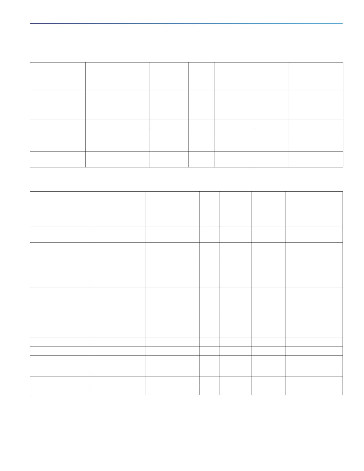
Table 19
Industrial and Rugged SFPs—Fiber-Optic SFP Module Port Cabling Specifications (continued)
Type of SFP
Model
Wavelength
Fiber
Core
Modal
Cable Distance
Module
(nanometers)
Type
Size/Claddin
Bandwidth
g Size
(MHz/km)
(micron)
100BASE-FX
GLC-FE-100FX-RGD
1310
MMF
62.5/125
160
1.24 miles (2 km)
62.5/125
200
50/125
400
50/125
500
100BASE-LX10
GLC-FE-100LX-RGD
1310
SMF
G.652
—
6.2 miles (10 km)
1000BASE-BX- D
GLC-BX40-D-I
1550
SMF
G.652
—
24.9 miles (40 km)
GLC-BX40-DA-I
1490
24.9 miles (40 km)
GLC-BX80-D-I)
1570
49.8 miles (80 km)
1000BASE-BX-U
GLC-BX40-U-I
1310
SMF
G.652
—
24.9 miles (40 km)
GLC-BX80-U-I
1490
49.8 miles (80 km)
Table 20
Commercial SFPs—Fiber-Optic SFP Module Port Cabling Specifications
Type of SFP Module
Model
Wavelength
Fiber
Core
Modal
Cable Distance
(nanometers)
Type
Size/
Bandwidth
Cladding
(MHz/km)
Size
(micron)
1000BASE-BX10-D
GLC-BX-D
1490 TX
SMF
G.652
—
6.2 miles (10 km)
1310 RX
1000BASE-BX10-U
GLC-BX-U
1490 TX
SMF
G.652
—
6.2 miles (10 km)
1310 RX
1000BASE-LX/LH
GLC-LH-SM
1310
MMF
62.5/125
500
1804 feet (550 m)
50/125
400
1804 feet (550 m)
50/125
500
1804 feet (550 m)
SMF
G.652
—
6.2 miles (10 km)
1000BASE-SX
GLC-SX-MM
850
MMF
62.5/125
160
722 feet (220 m)
62.5/125
200
902 feet (275 m)
50/125
400
1640 feet (500 m)
50/125
500
1804 feet (550 m)
100BASE-BX10-D
GLC-FE-100BX-D
1310 TX
SMF
G.652
—
6.2 miles (10 km)
1550 RX
100BASE-BX10-U
GLC-FE-100BX-U
1310 TX
SMF
G.652
—
6.2 miles (10 km)
100BASE-EX
GLC-FE-100EX
1310
SMF
G.652
—
24.9 miles (40 km)
100BASE-FX SFP
GLC-FE-100FX
1310
MMF
50/125
500
6562 feet (2 km)
62.5/125
100BASE-LX10
GLC-FE-100LX
1310
SMF
G.652
—
6.2 miles (10 km)
100BASE-ZX
GLC-FE-100ZX
1550
SMF
G.652
—
49.7 miles (80 km)
91

Table 20
Commercial SFPs—Fiber-Optic SFP Module Port Cabling Specifications (continued)
Type of SFP Module
Model
Wavelength
Fiber
Core
Modal
Cable Distance
(nanometers)
Type
Size/
Bandwidth
Cladding
(MHz/km)
Size
(micron)
1000BASE-CWDM
CWDM
1470, 1490, 1510,
SMF
G.652
—
62 miles (100 km)
1530, 1550, 1570,
1590, 1610
1000BASE-DWDM
DWDM
1530.33, 1531.12,
SMF
G.652
—
62 miles (100 km)
1531.90, 1532.68,
1534.25, 1535.04,
1535.82, 1538.19,
1539.77, 1539.98,
1539.77, 1540.56,
1542.14, 1542.94,
1544.53, 1546.12,
1546.92, 1547.72,
1548.51, 1550.12,
1550.92, 1551.72,
1552.52, 1554.13,
1554.94, 1555.75,
1556.55, 1558.17,
1558.98, 1559.79,
1560.61
1000BASE-T
GLC-T
—
MMF
—
—
328 ft. (100 m)
View the CWDM data sheet at
99_Products_Data_Sheet.html
View the DWDM data sheet at
Table 21
Extended Temperature SFPs—Fiber-Optic SFP Module Port Cabling Specifications
Type of SFP Module
Model
Wavelength
Fiber
Core Size/
Modal
Cable Distance
(nanometers)
Type
Cladding
Bandwidth
Size
(MHz/km)
(micron)
1000BASE-LX/LH
SFP-GE-L
1300
MMF
62.2
500
1804 feet (550 m)
or SMF
50
400
1804 feet (550 m)
50
500
1804 feet (550 m)
9/10
—
6.2 miles (10 km)
1000BASE-LX/LH
GLC-LH-SMD
1310
MMF
62.5
500
1804 feet (550 m)
50.0
400
1804 feet (550 m)
50.0
500
1804 feet (550 m)
SMF
G.652
—
6.2 miles (10 km)
1000BASE-EX
GLC-EX-SMD
1310
SMF
G.652
—
24.9 miles (40 km)
92

Table 21
Extended Temperature SFPs—Fiber-Optic SFP Module Port Cabling Specifications (continued)
Type of SFP Module
Model
Wavelength
Fiber
Core Size/
Modal
Cable Distance
(nanometers)
Type
Cladding
Bandwidth
Size
(MHz/km)
(micron)
1000BASE-SX
SFP-GE-S
850
MMF
62.5
160
722 feet (220 m)
62.5
200
902 feet (275 m)
50.0
400
1640 feet (500 m)
50.0
500
1804 feet (550 m)
1000BASE-SX
GLC-SX-MMD
850
MMF
62.5
160
722 feet (220 m)
62.5
200
902 feet (275 m)
50.0
400
1640 feet (500 m)
50.0
500
1804 feet (550 m)
50.0
2000
3281 feet (1 km)
1000BASE-ZX
SFP-GE-Z
1550
SMF
9/10
—
43.5 miles (70 km)
SMF
8
62 miles (100 km)
Cable Pinouts
Figure 54
Two Twisted-Pair Straight-Through Cable Schematic for 10/100 Ports
Switch
Router or PC
3 TD+
3 RD+
6 TD-
6 RD-
1 RD+
1 TD+
2 RD-
2 TD-
Figure 55
Two Twisted-Pair Crossover Cable Schematic for 10/100 Ports
Switch
Switch
3 TD+
3 TD+
6 TD-
6 TD-
1 RD+
1 RD+
2 RD-
2 RD-
93
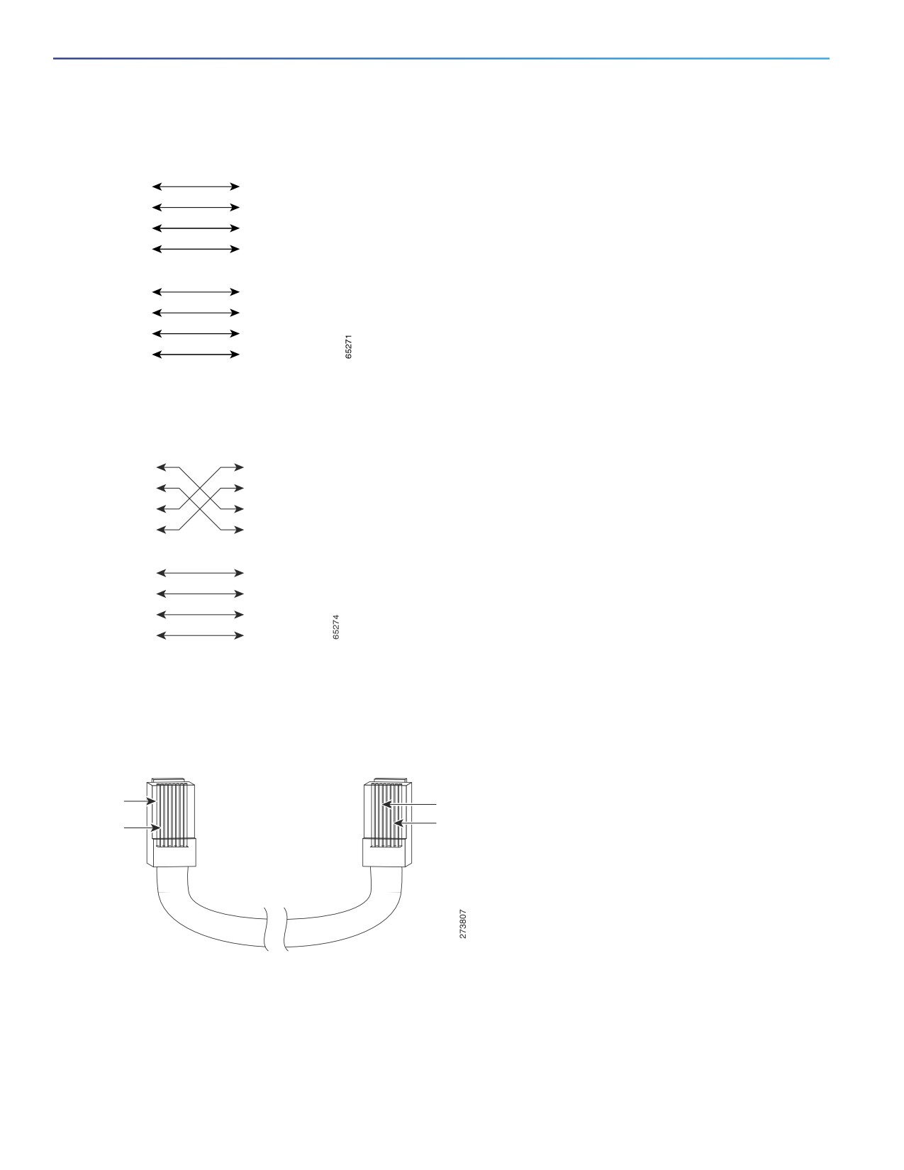
Figure 56
Four Twisted-Pair Straight-Through Cable Schematic for 1000BASE-T Ports
Switch
Router or PC
1
TP0+
1
TP0+
2
TP0-
2
TP0-
3
TP1+
3
TP1+
6
TP1-
6
TP1-
4
TP2+
4
TP2+
5
TP2-
5
TP2-
7
TP3+
7
TP3+
8
TP3-
8
TP3-
Figure 57
Four Twisted-Pair Crossover Cable Schematics for 1000BASE-T Ports
Switch
Switch
1 TP0+
1 TP0+
2 TP0-
2 TP0-
3 TP1+
3 TP1+
6 TP1-
6 TP1-
4 TP2+
4 TP2+
5 TP2-
5 TP2-
7 TP3+
7 TP3+
8 TP3-
8 TP3-
To identify a crossover cable, hold the cable ends side-by-side, with the tab at the back. The wire connected to pin 1
on the left end should be the same color as the wire connected to pin 3 on the right end. The wire connected to pin 2
on the left end should be the same color as the wire connected to pin 6 on the right end.
Figure 58
Identifying a Crossover Cable
Pin 1
Pin 3
Pin 6
Pin 2
Console Port Adapter Pinouts
The console port uses an 8-pin RJ-45 connector, which is described in b and Table 23 on page 95. If you did not order
a console cable, you need to provide an RJ-45-to-DB-9 adapter cable to connect the switch console port to a PC
console port. You need to provide an RJ-45-to-DB-25 female DTE adapter if you want to connect the switch console
94

port to a terminal. You can order an adapter (part number ACS-DSBUASYN=). For console port and adapter pinout
information, see Table 22 on page 95 and Table 23 on page 95.
Table 22 on page 95 lists the pinouts for the console port, the RJ-45-to-DB-9 adapter cable, and the console device.
Table 22
Console Port Signaling Using a DB-9 Adapter
Switch Console Port (DTE)
RJ-45-to-DB-9
Console
Terminal Adapter
Device
Signal
DB-9 Pin
Signal
RTS
8
CTS
DTR
6
DSR
TxD
2
RxD
GND
5
GND
RxD
3
TxD
DSR
4
DTR
CTS
7
RTS
Table 23 on page 95 lists the pinouts for the switch console port, RJ-45-to-DB-25 female DTE adapter, and the console
device.
Note: The RJ-45-to-DB-25 female DTE adapter is not supplied with the switch. You can order this adapter from Cisco
(part number ACS-DSBUASYN=).
Table 23
Console Port Signaling Using a DB-25 Adapter
Switch Console
RJ-45-to-DB-25
Console
Port (DTE)
Adapter
Device
Signal
DB-25 Pin
Signal
RTS
5
CTS
DTR
6
DSR
TxD
3
RxD
GND
7
GND
RxD
2
TxD
DSR
20
DTR
CTS
4
RTS
95
96
Running Express Setup
When you first set up the switch, you should use Express Setup to enter the initial IP information. This process enables
the switch to connect to local routers and the Internet. You can then access the switch through the IP address for
additional configuration.
You need this equipment to set up the switch:
PC with Windows XP, Vista, or Windows 7
Web browser (Internet Explorer 6.0, 7.0 or Firefox 1.5, 2.0, 3.0 or later) with JavaScript enabled
Straight-through or crossover Category 5 or higher grade cable
Before running Express Setup, disable any pop-up blockers or proxy settings on your browser and any wireless client
running on your PC.
To run Express Setup:
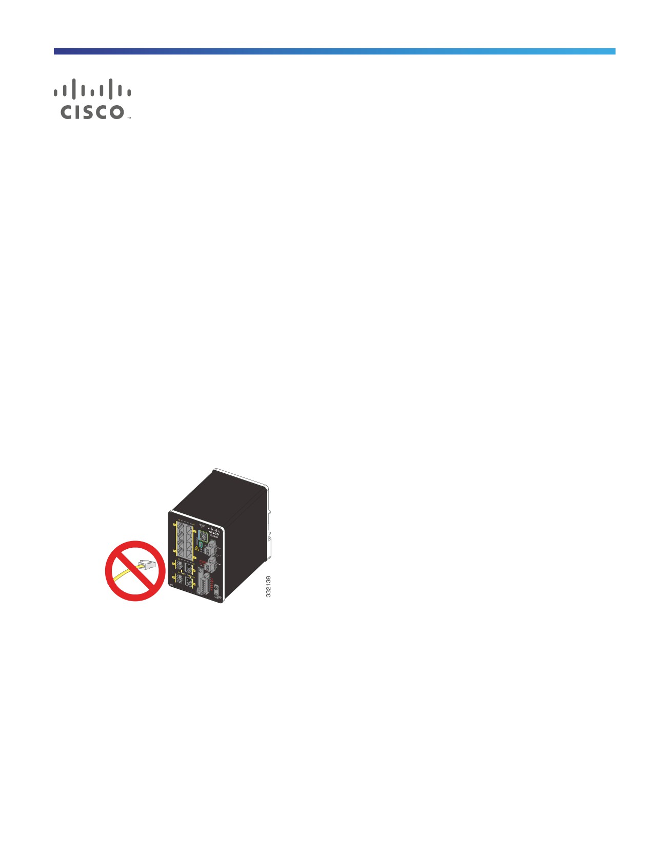
1. Make sure that nothing is connected to the switch.
During Express Setup, the switch acts as a DHCP server. If your PC has a static IP address, temporarily configure
your PC settings to use DHCP before going to the next step.
Note: Write down the static IP address. You will need this IP address in Step 13.
2. Connect power to the switch.
See the wiring instructions in Grounding the Switch, page 40 and Wiring the DC Power Source, page 46.
3. After the switch powers on, it begins the boot fast sequence, which can take up to 60 seconds.
During boot fast, the SYS LED blinks green, and the other LEDs turn green.
When boot fast is complete, the SYS LED turns green, and the other LEDs turn off.
97
Troubleshooting:
If the SYS LED is off (system not powered on), continues to blink green (POST in progress), or is solid red (Fault),
contact the Cisco Technical Assistance Center (TAC). The SYS LED should be solid green when operating normally
in Cisco IOS.
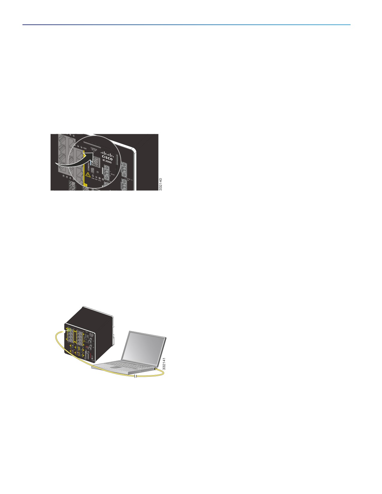
4. Press the Express Setup button for 2 to 3 seconds. This button is recessed behind the front panel, so you can use
a simple tool, such as a paper clip.
When you press the Express Setup button, a switch port LED begins blinking green.
5. Connect a Category 5 Ethernet cable (not provided) from the blinking switch port to the Ethernet port on your PC.
The port LEDs on your PC and on the switch blink green while the switch configures the connection. The green port
LEDs indicate a successful connection.
Troubleshooting:
If the port LEDs do not turn green after about 30 seconds, make sure that:
— You connected the Ethernet cable to one of the downlink switch ports (not to an uplink port such as the
dual-purpose port).
— You are using an undamaged Category 5 or higher grade cable.
— The other device is turned on.
6. When the Setup LED turns solid green, start a browser session on the PC. A login prompt appears.
7. Leave the username blank and enter the default password, cisco.
Note: The switch ignores text in the username field.
The Express Setup window appears.
Troubleshooting:
If the Express Setup window does not appear, make sure that any pop-up blockers or proxy settings on your browser
are disabled and that any wireless client is disabled on your PC or laptop.
98
8.
Enter all entries in English letters and Arabic numbers.
Required Fields
In the Network Settings fields:
— Management Interface (VLAN): We recommend using the default, VLAN 1. The management VLAN establishes
an IP connection to the switch.
Note: Enter a new VLAN ID only if you want to change the management interface through which you manage the
switch. The VLAN ID range is 1 to 1001.
— IP Assignment Mode: We recommend using the default, Static, so that the switch always has the IP address
that you assign. Use the DHCP setting when you want the switch to automatically obtain an IP address from a
DHCP server.
— IP Address: Enter the IP address for the switch. You can later use the IP address to access the switch through
Device Manager.
— Subnet Mask: Select a mask from the drop-down list.
— Default Gateway: Enter the IP address of the router.
— Switch Password: Enter a password. The password can be from 1 to 25 alphanumeric characters, can start with
a number, is case sensitive, allows embedded spaces, but does not allow spaces at the beginning or end. In the
Confirm Password field, enter the password again.
Note: You must change the password from the default password, cisco.
9.
Enter the Control Industrial Protocol (CIP) VLAN settings:
— CIP VLAN: Enter the VLAN on which CIP will be enabled. The CIP VLAN can be the same as the management
VLAN, or you can isolate CIP traffic on another VLAN that is already configured on the switch. The default CIP
VLAN is VLAN 1. Only one VLAN on a switch can have CIP enabled.
— IP Address: Enter the IP address for the CIP VLAN. If the CIP VLAN is different from the management VLAN, you
must specify an IP address for the CIP VLAN. Make sure that the IP address that you assign to the switch is not
being used by another device in your network.
— Subnet Mask: Select a mask from the drop-down list.
For more information about the CIP VLAN settings, click Help on the toolbar.
10. Optional settings
You can enter the optional information now, or enter it later by using Device Manager. For more information about
the Express Setup fields, see the online help for the Express Setup window.
Click Submit to save your changes and to complete the initial setup.
For more information about the optional settings, click Help on the toolbar.
11. After you click Submit, these events occur:
— The switch is configured and exits Express Setup mode.
— The browser displays a warning message and tries to connect with the earlier switch IP address. Typically,
connectivity between the PC and the switch is lost because the configured switch IP address is in a different
subnet from the IP address on the PC.
99
12. Turn off DC power at the source, disconnect all cables to the switch, and install the switch in your network. See
Management Options, page 26 for information about configuring and managing the switch.
13. If you changed the static IP address on your PC in Step 1, change it to the previously configured static IP address.
14. You can now manage the switch by using the Cisco Network Assistant, Device Manager, or the Cisco IOS Command
Line Interface (CLI). See Management Options, page 26 for information about configuring and managing the switch.
You can display Device Manager by following these steps:
a. Start a web browser on your PC or laptop.
b. Enter the switch IP address, username, and password (assigned in Step 7) in the web browser, and press Enter.
The Device Manager page appears.
Troubleshooting
If the Device Manager page does not appear:
Confirm that the port LED for the switch port connected to your network is green.
Confirm that the PC or laptop that you are using to access the switch has network connectivity by connecting it to a
well-known web server in your network. If there is no network connection, troubleshoot the network settings on the
PC or laptop.
Make sure that the switch IP address in the browser is correct.
If the switch IP address in the browser is correct, the switch port LED is green, and the PC or laptop has network
connectivity, continue troubleshooting by reconnecting the PC or laptop to the switch. Configure a static IP address
on the PC or laptop that is in the same subnet as the switch IP address. For example:
— If your switch IP address is 172.20.20.85 and your PC or laptop IP address is 172.20.20.84, both devices are in
the same network.
— If your switch IP address is 172.20.20.85 and your PC or laptop IP address is 10.0.0.2, the devices are in
different networks and cannot communicate directly.
When the LED on the switch port connected to the PC or laptop is green, reenter the switch IP address in a web
browser to display the Device Manager. When Device Manager appears, you can continue with the switch
configuration.
100
Configuring the Switch with the CLI-Based
Setup Program
This appendix provides a command-line interface (CLI)-based setup procedure for a switch. For information about
setting up the switch by using Express Setup, see Running Express Setup, page 97.
Before connecting the switch to a power source, review the safety warnings in Warnings, page 29.
For installation procedures, see Switch Installation, page 29.
Accessing the CLI Through the Console Port
You can enter Cisco IOS commands and parameters through the CLI. Use one of these options to access the CLI:
RJ-45 Console Port, page 102
USB Mini-Type B Console Port, page 103
Removing the USB Mini-Type B Console Port Cover
To remove the cover from the USB mini-type B console port:
1. Use a Phillips screwdriver to loosen the captive screw on the USB mini-type B console port cover. See Figure 59 on
page 102.
2. Remove the cover.
101
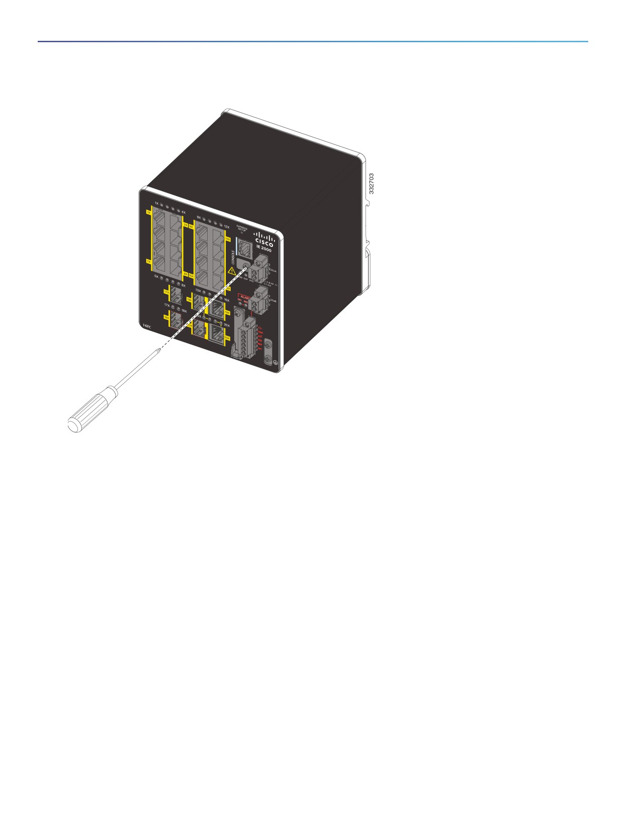
Figure 59
Removing the USB Mini-Type B Console Port Cover
RJ-45 Console Port
1. Connect the RJ-45-to-DB-9 adapter cable to the 9-pin serial port on the PC. Connect the other end of the cable to
the switch console port.
2. Start the terminal-emulation program on the PC or the terminal. The program, frequently a PC application such as
HyperTerminal or ProcommPlus, makes communication between the switch and your PC or terminal possible.
102
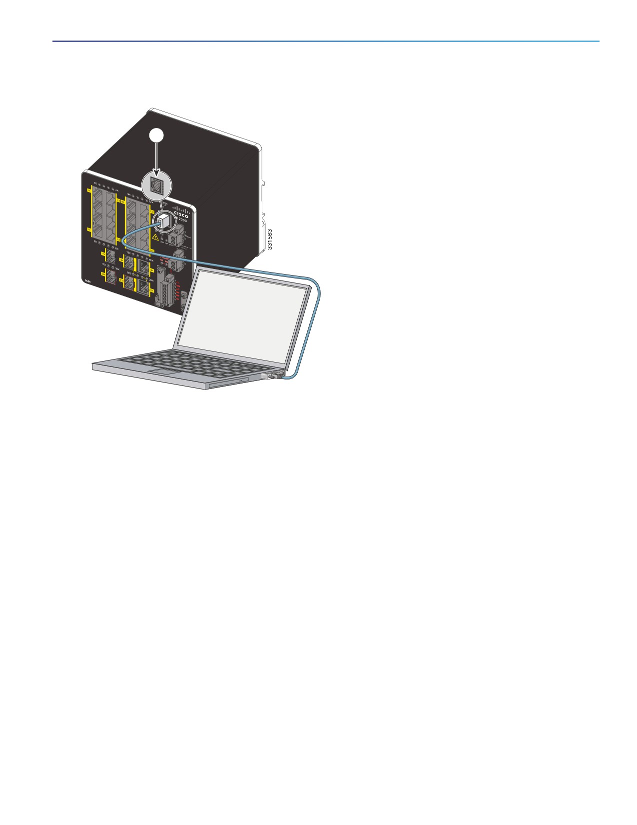
Figure 60
Connecting the Console Cable
1
1
RJ-45 console port
2
Console cable (RJ-45-to-DB-9 adapter cable)
3. Configure the baud rate and character format of the PC or terminal to match the console port characteristics:
—
9600 baud
—
8 data bits
—
1 stop bit
— No parity
— None (flow control)
4. Connect power to the switch as described in Connecting to Power, page 39.
The PC or terminal displays the bootloader sequence.
5. Press Enter to display the setup prompt.
6. Follow the steps in Completing the Setup Program, page 106.
USB Mini-Type B Console Port
1. If you are connecting the switch USB-mini console port to a Windows-based PC for the first time, install a USB driver.
See Installing the Cisco Microsoft Windows XP, 2000, Vista, 7, 8, and 10 USB Device Driver, page 105 for more
information.
103
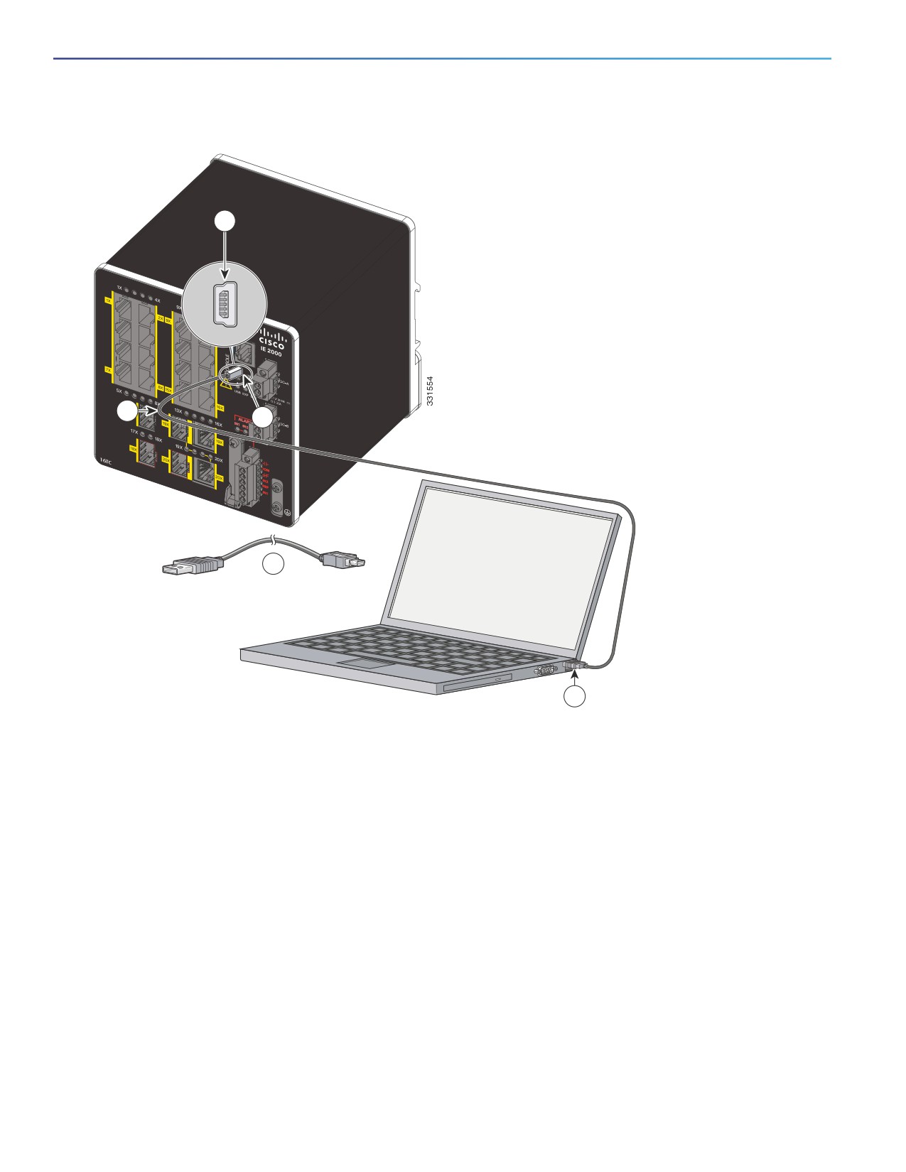
Figure 61
Connecting the USB-Mini Console Cable
1
2
1
2
3
1
USB-mini console port
3
USB port on the PC
2
USB cable
2. Connect an USB cable to the PC USB port, and connect the other end of the cable to the switch mini-B
(5-pin-connector) USB-mini console port. See Figure 61.
3. Identify the COM port assigned to the USB-mini console port:
a. Choose Start > Control Panel > Systems.
b. Click the Hardware tab and choose Device Manager. Expand the Ports section. The assigned COM port appears
in parenthesis at the end of the line with this entry: Cisco USB System Management Console.
4. Start the terminal-emulation program on the PC or the terminal.
The program, frequently a PC application such as HyperTerminal or ProcommPlus, makes communication possible
between the switch and your PC or terminal.
5. Configure the COM port.
6. Configure the baud rate and character format of the PC or terminal to match the console port characteristics:
104
—
9600 baud
—
8 data bits
—
1 stop bit
— No parity
— None (flow control)
7. Connect power to the switch as described in Connecting to Power, page 39.
The PC or terminal displays the bootloader sequence.
8. Press Enter to display the setup prompt.
9. Follow the steps in Completing the Setup Program, page 106.
Installing the Cisco Microsoft Windows XP, 2000, Vista, 7, 8, and 10 USB Device
Driver
A USB device driver must be installed the first time a Microsoft Windows-based PC is connected to the USB console
port on the switch. Use this procedure to install the USB driver on Windows XP, Windows 2000, Windows Vista,
Windows 7, Windows 8, and Windows 10.
1.
Obtain the file Cisco_usbconsole_driver_3_1.zip from the Cisco.com website
The file details are as follows:
— Description: Cisco_usbconsole_driver_3_1.zip
— Release: 3.1
— Release Date: 27/Nov/2014
— File Name: Cisco_usbconsole_driver_3_1.zip
— Size: 14.35 MB (15045453 bytes)
— MD5 Checksum: eff2e955edcdc70209e6f9c8f6bd59cd
2.
Unzip the file and install the corresponding exe file.
3.
Navigate to the Device Manager window by performing a search in WIndows for Device Manager and opening it.
4.
Connect the USB cable from the Windows PC to the Cisco switch.
5.
From the Device Manager page, expand Ports (COM & LPT). Select USB Serial Port. Right-click and select Update
Driver Software ...
6.
In the Update Driver Software window, select Browse my computer for driver software. Then choose Let me pick
from a list of device drivers on my computer and click Next.
7.
Enable Show compatible hardware and choose Cisco Serial as the model. Click Next.
After the update is completed, Windows displays Windows has successfully updated your driver software.
8.
Click Close.
105
Uninstalling the Cisco Microsoft Windows XP, 2000, Vista, 7, 8, and 10 USB Driver
Note: Disconnect the switch console terminal before uninstalling the driver.
1. Run setup.exe for Windows 32-bit or setup(x64).exe for Windows-64bit.
2. Click Next.
3. When the InstallShield Wizard for Cisco Virtual Com appears, click Next.
4. When the Program Maintenance window appears, select the Remove radio button.
5. Click Next.
6. When the Remove the Program window appears, click Remove.
If a User Account Control warning appears, click Allow - I trust this program to proceed.
7. When the InstallShield Wizard Completed window appears, click Finish.
Entering the Initial Configuration Information
To set up the switch, you must complete the setup program, which runs automatically after the switch is powered on.
Assign an IP address and any other configuration information necessary for the switch to communicate with the local
routers and the Internet. This information is also required if you plan to use Device Manager or Cisco Network Assistant
to configure and manage the switch.
IP Settings
Gather this information from your network administrator before completing the setup program:
Switch IP address
Subnet mask (IP netmask)
Default gateway (router)
Enable secret password
Enable password
Telnet password
Completing the Setup Program
To complete the setup program and to create an initial configuration for the switch:
1. Enter Yes at these two prompts:
Would you like to enter the initial configuration dialog? [yes/no]: yes
At any point you may enter a question mark '?' for help.
Use ctrl-c to abort configuration dialog at any prompt.
Default settings are in square brackets '[]'.
Basic management setup configures only enough connectivity
for management of the system, extended setup will ask you
to configure each interface on the system.
Would you like to enter basic management setup? [yes/no]: yes
106
2.
Enter a hostname for the switch, and press Return.
On a command switch, the hostname is limited to 28 characters; on a member switch, it is limited to 31 characters.
Do not use -n, where n is a number, as the last character in a hostname for any switch.
Enter host name [Switch]: host_name
3.
Enter an enable secret password, and press Return.
The password can be from 1 to 25 alphanumeric characters, can start with a number, is case sensitive, allows
spaces, but ignores leading spaces. The secret password is encrypted, and the enable password is in plain text.
Enter enable secret: secret_password
4.
Enter an enable password, and press Return.
Enter enable password: enable_password
5.
Enter a virtual terminal (Telnet) password, and press Return.
The password can be from 1 to 25 alphanumeric characters, is case sensitive, allows spaces, but ignores leading
spaces.
Enter virtual terminal password: terminal-password
6.
(Optional) Configure Simple Network Management Protocol (SNMP) by responding to the prompts.
You can also configure SNMP later through the CLI, Device Manager, or the Cisco Network Assistant application.
To configure SNMP later, enter no.
Configure SNMP Network Management? [no]: no
7.
Enter the interface name (physical interface or VLAN name) of the interface that connects to the management
network, and press Return.
For this release, always use vlan1 as that interface.
Enter interface name used to connect to the
management network from the above interface summary: vlan1
8. Configure the interface by entering the switch IP address and subnet mask and pressing Return.
The IP address and subnet masks shown here are examples.
Configuring interface vlan1:
Configure IP on this interface? [yes]: yes
IP address for this interface: 10.4.120.106
Subnet mask for this interface [255.0.0.0]: 255.0.0.0
9.
Enter Y to configure the switch as the cluster command switch. Enter N to configure it as a member switch or as a
standalone switch.
If you enter N, the switch appears as a candidate switch in the Cisco Network Assistant GUI. You can configure the
switch as a command switch later through the CLI, Device Manager, or the Cisco Network Assistant application.
To configure it later, enter no.
Would you like to enable as a cluster command switch? [yes/no]: no
You have now completed the initial configuration of the switch, and the switch displays its initial configuration script:
107
The following configuration command script was created:
hostname Switch
enable secret 5
$1$ZQRe$DPulYXyQLm77v/a4Bmu6Y.
enable password cisco
line vty 0 15
password cisco
no snmp-server
!
!
interface Vlan1
no shutdown
ip address 10.4.120.106 255.0.0.0
!
interface FastEthernet1/1
!
interface FastEthernet1/2
!
interface FastEthernet1/3
!
...(output abbreviated)
!
interface GigabitEthernet1/1
!
interface GigabitEthernet1/2
!
end
These choices appear:
[0] Go to the IOS command prompt without saving this config.
[1] Return back to the setup without saving this config.
[2] Save this configuration to nvram and exit.
If you want to save the configuration and use it the next time the switch reboots, save it in NVRAM
by selecting option 2.
Enter your selection [2]:2
10. Make your selection, and press Return.
After you complete the setup program, the switch can run the default configuration that you created. To change this
configuration or perform other management tasks, use one of these tools:
Command-line interface (CLI)
Cisco Network Assistant (for one or more switches)
To use the CLI, enter commands at the Switch> prompt through the console port by using a terminal emulation program
or through the network by using Telnet.
For configuration information, see the Cisco IE 2000 Switch Software Configuration Guide or the Cisco IE 2000 Switch
Command Reference.
To use the Cisco Network Assistant, see the Getting Started with Cisco Network Assistant guide on Cisco.com.
108