Cisco IE 2000 Switch Hardware Installation Guide (2016) - page 2
For 100BASE-FX fiber-optic ports, the cable length from a switch to an attached device cannot exceed 6562 ft (2
km).
Operating environment is within the ranges listed in Technical Specifications, page 81
Clearance to front and rear panels meets these conditions:
— Front-panel LEDs can be easily read.
— Access to ports is sufficient for unrestricted cabling.
— Front-panel direct current (DC) power connectors and the alarm connector are within reach of the connection
to the DC power source.
Airflow around the switch must be unrestricted. To prevent the switch from overheating, you must have the following
minimum clearances:
— Top and bottom: 2.0 in. (50.8 mm)
— Sides: 2.0 in. (50.8 mm)
— Front: 2.0 in. (50.8 mm)
Temperature surrounding the unit does not exceed 140°F (60°C).
Note: When the switch is installed in an industrial enclosure, the temperature within the enclosure is greater than
normal room temperature outside the enclosure.
Note: The temperature inside the enclosure cannot exceed 140°F (60°C), the maximum ambient enclosure
temperature of the switch.
Cabling is away from sources of electrical noise, such as radios, power lines, and fluorescent lighting fixtures.
Connect the unit only to a Class 2 DC power source.
Verifying Package Contents
The Cisco IE 2000 Switch Getting Started Guide on Cisco.com describes the box contents. If any item is missing or
damaged, contact your Cisco representative or reseller for support.
Installing or Removing the Flash Memory Card (Optional)
The software /firmware is stored on the internal flash memory in the Cisco IE2000 switch. Optionally, you can order and
install an SD memory card (SD-IE-1GB=) to store the software and the configuration changes. If you need to replace the
switch, you can simply insert the SD memory card instead of configuring the new switch.
Warning: Do not insert or remove the flash card while power is on; an electrical arc can occur. This could cause an
explosion in hazardous location installations. Be sure that power is removed or the area is nonhazardous before
proceeding. Statement 379
To install or replace the flash memory card, follow these steps:
1. On the front of the switch, locate the door that protects the flash memory card slot. Loosen the captive screw at the
top of the door using a Phillips screwdriver to open the door. See Figure 12 on page 34.
33
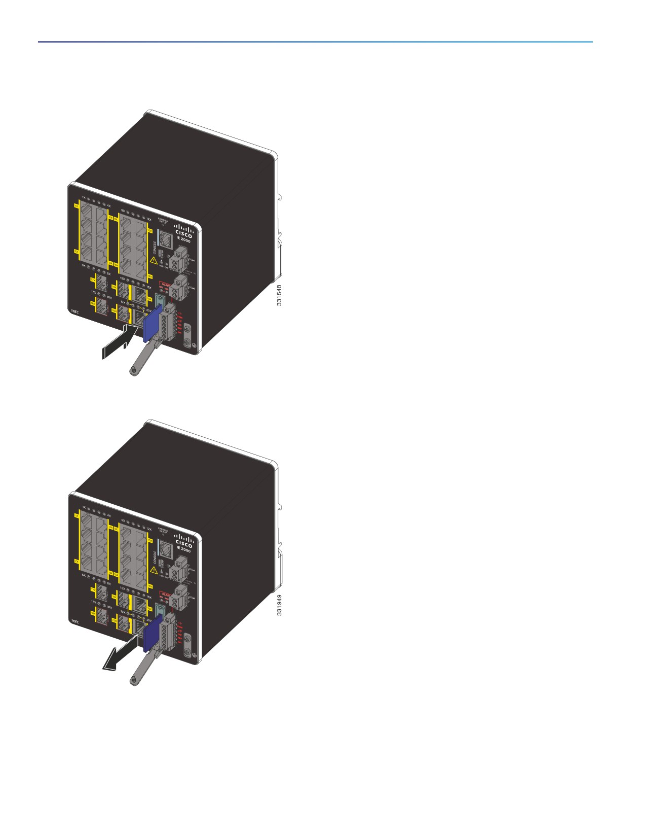
Figure 12
Installing the Flash Memory Card in the Switch
Figure 13
Removing the Flash Memory Card from the Switch
2. Install or remove the card:
— To install a card, slide it into the slot, and press it in until it clicks in place. The card is keyed so that you cannot
insert it the wrong way.
— To remove the card, push it in until it releases for it to pop out. Place it in an antistatic bag to protect it from static
discharge.
34
3. After the card is installed, close the guard door and fasten the captive screw using a Phillips screwdriver to keep the
door in place.
Connecting to a Console Port
You can enter Cisco IOS commands and parameters through the CLI. Use one of these options to access the CLI:
RJ-45 Console Port, page 35
USB Mini-Type B Console Port, page 36
Warning: If you connect or disconnect the console cable with power applied to the switch or any device on the
network, an electrical arc can occur. This could cause an explosion in hazardous location installations. Be sure that
power is removed or the area is nonhazardous before proceeding.
Statement 1080
RJ-45 Console Port
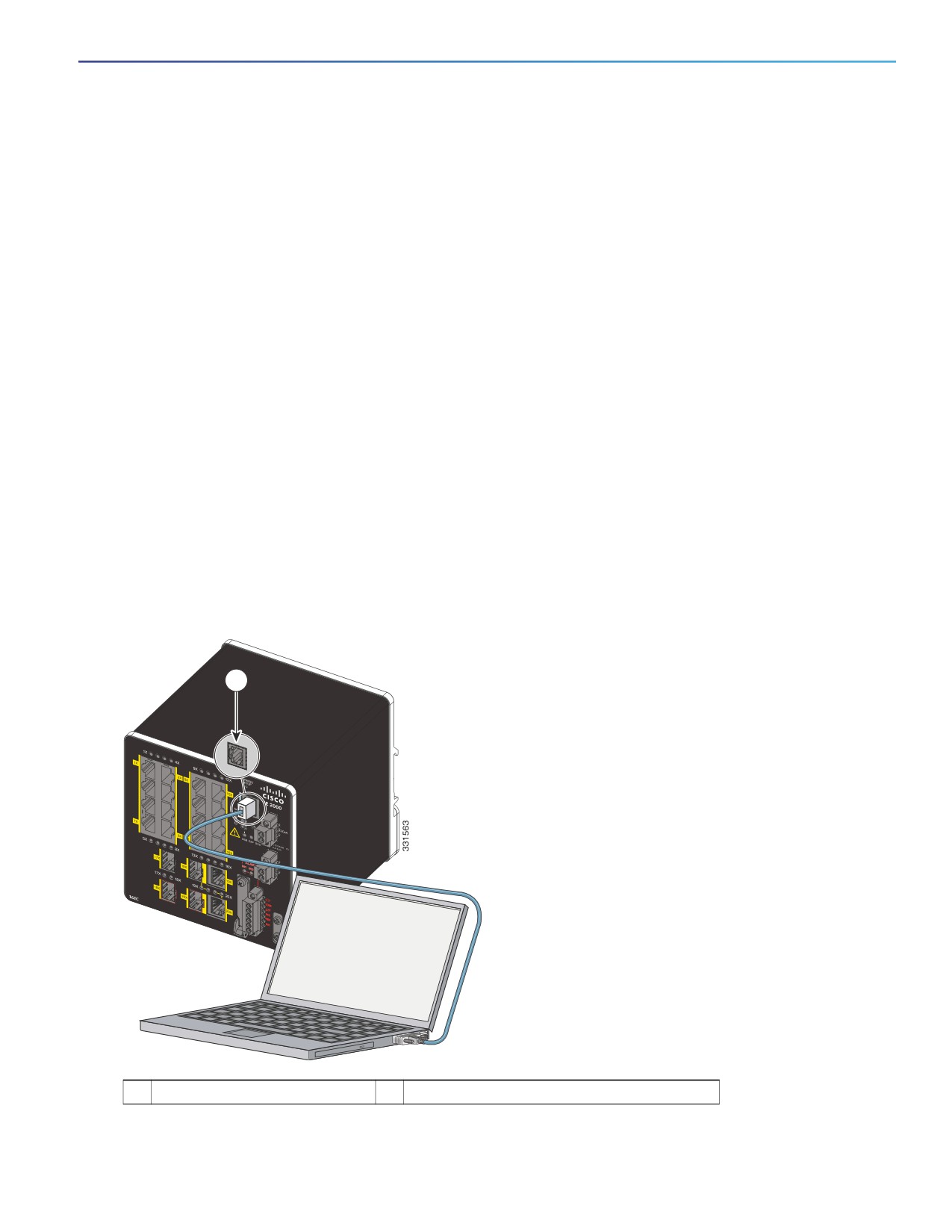
1. Connect the RJ-45-to-DB-9 adapter cable to the 9-pin serial port on the PC (see Figure 14 on page 35).
2. Connect the other end of the cable to the switch console port.
3. Start the terminal-emulation program on the PC or the terminal.
The program, frequently a PC application such as HyperTerminal or PuTTy, makes communication between the
switch and your PC or terminal possible.
Figure 14
Connecting the Console Cable
1
1
RJ-45 console port
2
Console cable (RJ-45-to-DB-9 adapter cable)
35
4. Configure the baud rate and character format of the PC or terminal to match the console port characteristics:
—
9600 baud
—
8 data bits
—
1 stop bit
— No parity
— None (flow control)
5. Connect power to the switch as described in Connecting to Power, page 39.
The PC or terminal displays the bootloader sequence.
6. Press Enter to display the setup prompt.
7. Follow the steps in Completing the Setup Program, page 106.
USB Mini-Type B Console Port
If you are connecting the switch USB-mini console port to a Windows-based PC for the first time, install a USB driver.
See Installing the Cisco Microsoft Windows XP, 2000, Vista, 7, 8, and 10 USB Device Driver, page 105 for more
information.
To remove the cover from the USB mini-type B console port:
1. Use a Phillips screwdriver to loosen the captive screw on the USB mini-type B console port cover. See Figure 15 on
page 37.
2. Remove the cover.
36
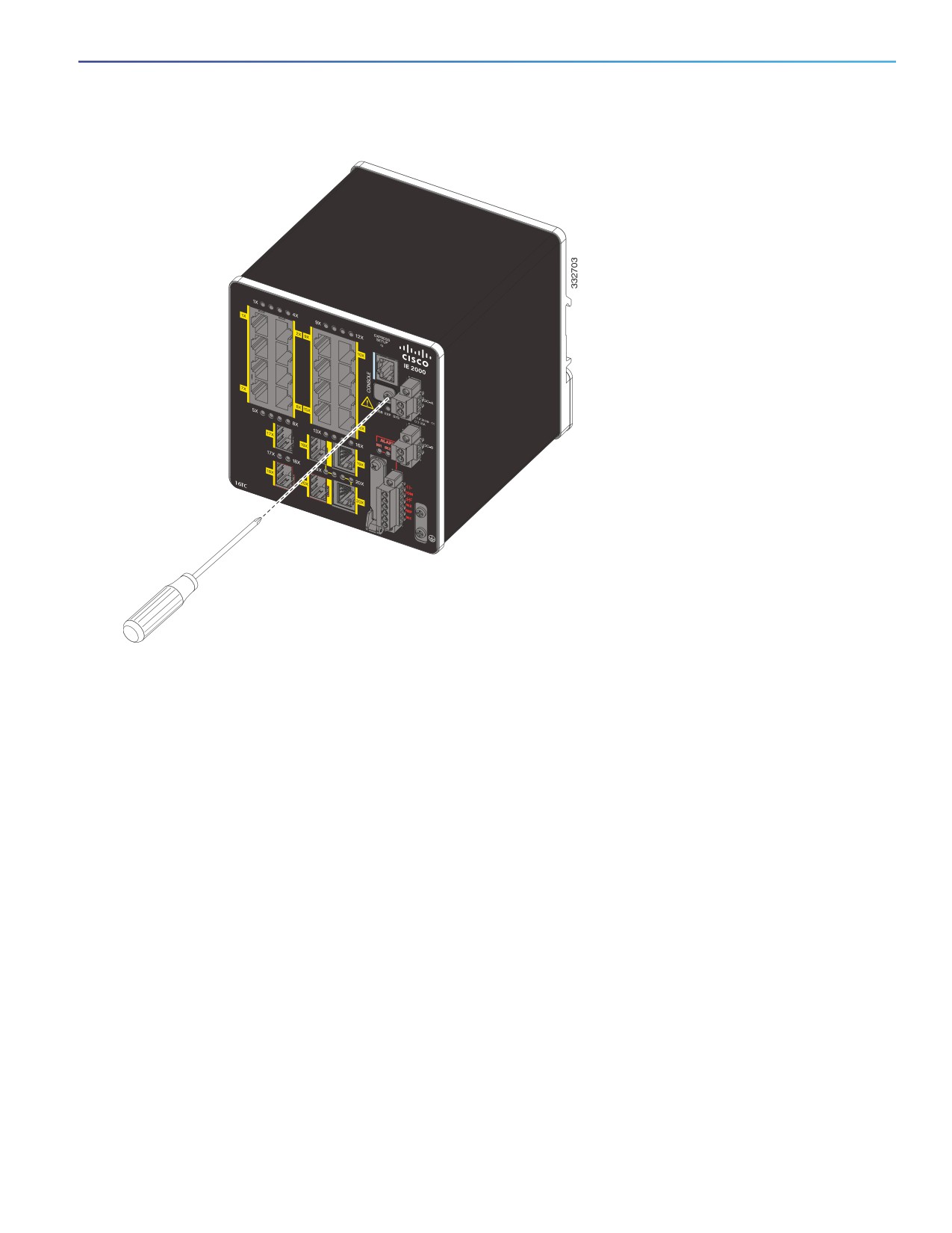
Figure 15
Removing the USB Mini-Type B Console Port Cover
3. Connect a USB cable to the PC USB port.
4. Connect the other end of the cable to the switch mini-B (5-pin connector) USB-mini console port. See Figure 16 on
page 38.
37
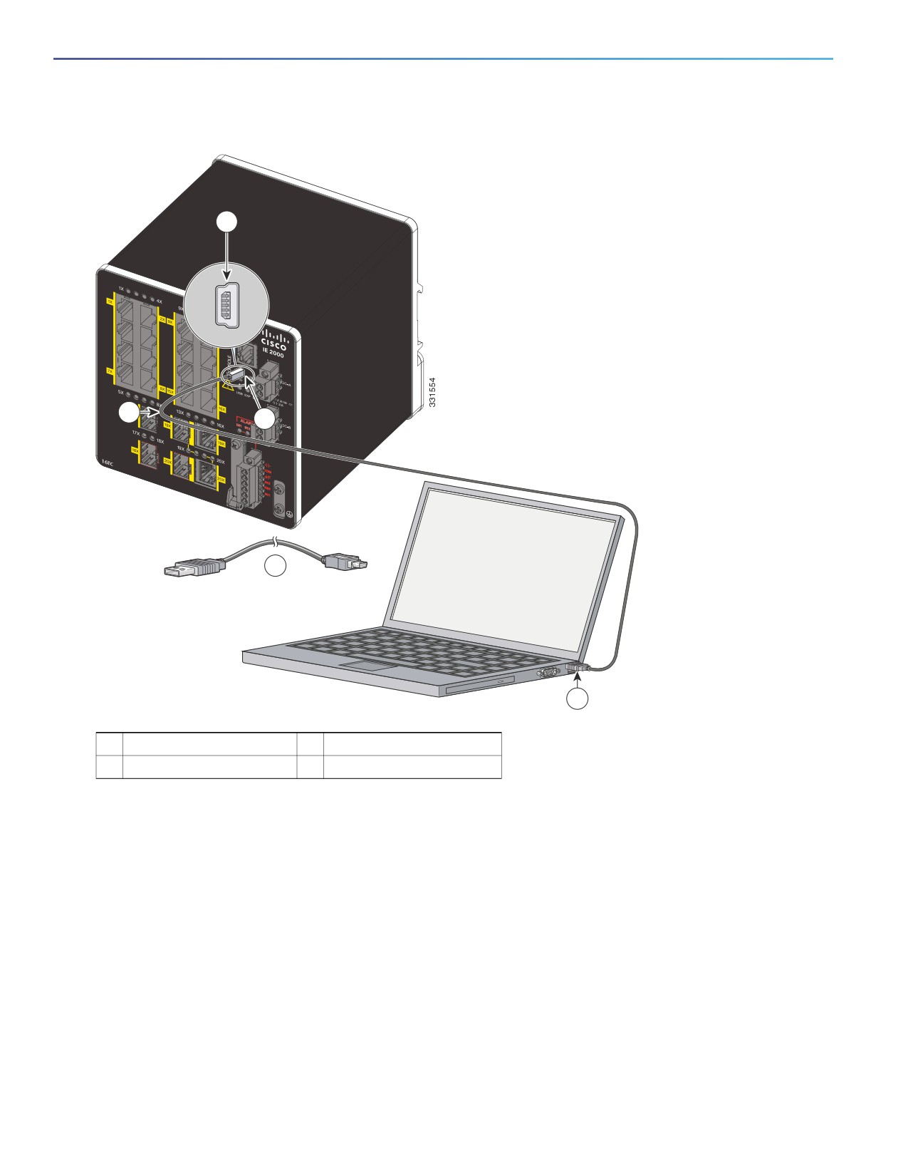
Figure 16
Connecting the USB-Mini Console Cable
1
2
1
2
3
1
USB-mini console port
3
USB port on the PC
2
USB cable
5. Identify the COM port assigned to the USB-mini console port:
a. Choose Start > Control Panel > Systems.
b. Click the Hardware tab and choose Device Manager. Expand the Ports section. The assigned COM port appears
in parenthesis at the end of the line with this entry: Cisco USB System Management Console.
6. Start the terminal-emulation program on the PC or the terminal.
The program, frequently a PC application such as HyperTerminal or ProcommPlus, makes communication possible
between the switch and your PC or terminal.
7. Configure the COM port.
8. Configure the baud rate and character format of the PC or terminal to match the console port characteristics:
—
9600 baud
—
8 data bits
38

—
1 stop bit
— No parity
— None (flow control)
9. Connect power to the switch as described in Connecting to Power, page 39.
10. When the PC or terminal displays the bootloader sequence, press Enter to display the setup prompt.
11. Follow the steps in Completing the Setup Program, page 106.
Connecting to Power
In systems configured with the redundant power option, connect each of the two power supplies to separate
independent power sources. If you fail to do this, your system might be susceptible to total power failure due to a fault
in the external wiring or a tripped circuit breaker.
Tools and Equipment
Obtain these necessary tools and equipment:
Ratcheting torque flathead screwdriver that exerts up to 15 in-lb (1.69 N-m) of pressure.
For the protective ground connector, obtain a single or pair of stud size 6 ring terminals (such as Hollingsworth part
number R3456B or equivalent).
Crimping tool (such as Thomas & Bett part number WT2000, ERG-2001, or equivalent).
10-gauge copper ground wire (such as Belden part number 9912 or equivalent).
For DC power connections, use UL- and CSA-rated, style 1007 or 1569 twisted-pair copper appliance wiring
material (AWM) wire (such as Belden part number 9318).
Wire-stripping tools for stripping 10- and 18-gauge wires.
A number-2 Phillips screwdriver.
A flat-blade screwdriver.
Supported Power Supplies
The supported power supplies are listed in Table 11 on page 39.
Table 11
Supported Power Supplies
PWR-IE170W-
PWR-IE170W-
PWR-IE65W-
PWR-IE65W-
PWR-IE50W-
PWR-IE50W-
PC-DC=
PC-AC=
PC-DC=
PC-AC=
AC-IEC=
AC=
Current
DC-DC
AC-DC
DC-DC
AC-DC
AC-DC
AC-DC
Input
10.8-60 VDC
90-264 VAC or
18-60
110/220 VAC
110/220 VAC
110/220VAC
106-300 VDC
VDC/4.3 Amp
and 88-300
and 88-300
VDC
VDC
Output
54 VDC/3.15 A
54 VDC/3.15 A
54VDC/1.2
54VDC/1.2
24VDC/2.1Am
24 VDC /
Amp
Amp
p
2.1Amp
39

Table 11
Supported Power Supplies
Dimensions
5.93 in H x
5.93 in H x
5.9 in H x
5.9 in. H x
5.8 in. H x
5.8 in. H x
4.47 in. W x
3.72 in. W x
2.1 in. W x
2.1 in. W x
2 in. W x
2 in. W x
5.75 in. D
5.60 in. D
4.9 in. D
4.9 in. D
4.4 in. D
4.4 in. D
Attachable?
Non-
Non-
Non-
Non-
Attachable
Attachable
attachable
attachable
attachable
attachable
unit
unit
Usage
Designed for
Designed for
Designed for
Designed for
Powers the
Powers the
PoE modules,
PoE modules,
PoE1
PoE modules,
switch.
switch. Cannot
can be used to
can be used to
modules, can
can be used
Cannot be
be used to
power the
power the
be used to
to power the
used to power
power PoE
switch.
switch.
power the
switch.
PoE modules,
modules,
switch.
which require
which require
48V DC.
48V DC.
1. The models that support PoE provide up to four ports of either PoE (15.4 W per port; IEEE 802.3af) or PoE+ (30 W per port;
IEEE 802.3at), depending on the power source used. See Power Requirements, page 82.
Installing the Power Converter on a DIN Rail, Wall, or Rack Adapter
You install the power converter on a DIN rail, wall, or rack as you would a switch module.
Warning: This equipment is supplied as “open type” equipment. It must be mounted within an enclosure that is
suitably designed for those specific environmental conditions that will be present and appropriately designed to
prevent personal injury resulting from accessibility to live parts. The interior of the enclosure must be accessible
only by the use of a tool. The enclosure must meet IP 54 or NEMA type 4 minimum enclosure rating standards.
Statement 1063
Caution: To prevent the switch assembly from overheating, there must be a minimum of 3 inches (76.19 mm) between
any other device and the top, bottom, or sides of the switch assembly.
Grounding the Switch
Follow the grounding requirements at your site.
Warning: This equipment must be grounded. Never defeat the ground conductor or operate the equipment in the
absence of a suitably installed ground conductor. Contact the appropriate electrical inspection authority or an
electrician if you are uncertain that suitable grounding is available. Statement 1024
Warning: This equipment is intended to be grounded to comply with emission and immunity requirements. Ensure
that the switch functional ground lug is connected to earth ground during normal use. Statement 1064
Caution: To ensure that the equipment is reliably connected to earth ground, follow the grounding procedure
instructions, and use a UL-listed ring terminal lug suitable for number 10-to-12 AWG wire, such as Hollingsworth part
number R3456B or equivalent)
Caution: Use at least a 4 mm2 conductor to connect to the external grounding screw.
The ground lug is not supplied with the switch. You can use one of the these options:
Single ring terminal
Two single ring terminals
To ground the switch to earth ground by using the ground screw, follow these steps:
1. Use a standard Phillips screwdriver or a ratcheting torque screwdriver with a Phillips head to remove the ground
screw from the front panel of the switch.
Store the ground screw for later use.
40
2. Use the manufacturer’s guidelines to determine the wire length to be stripped.
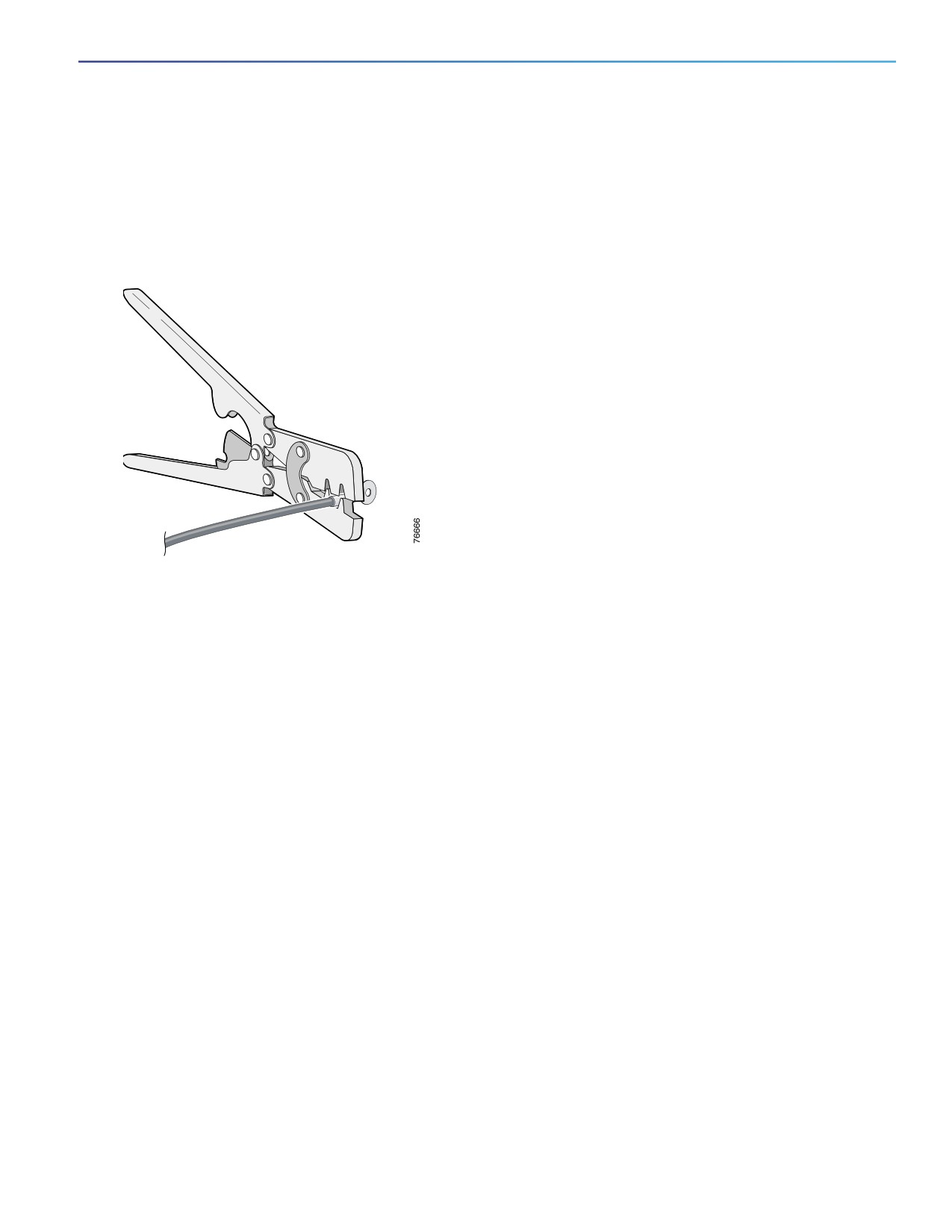
3. Insert the ground wire into the ring terminal lug, and using a crimping tool, crimp the terminal to the wire. See
Figure 17 on page 41.
If two ring terminals are being used, repeat this action for a second ring terminal.
Figure 17
Crimping the Ring Terminal
4. Slide the ground screw through the terminal.
5. Insert the ground screw into the functional ground screw opening on the front panel.
6. Use a ratcheting torque screwdriver to tighten the ground screws and ring terminal to the switch front panel to 3.5
in-lb (0.4 N-m). See Figure 18 on page 42 or Figure 19 on page 43.
Note: Do not exceed 3.5 in-lb (0.4 N-m) of torque.
41
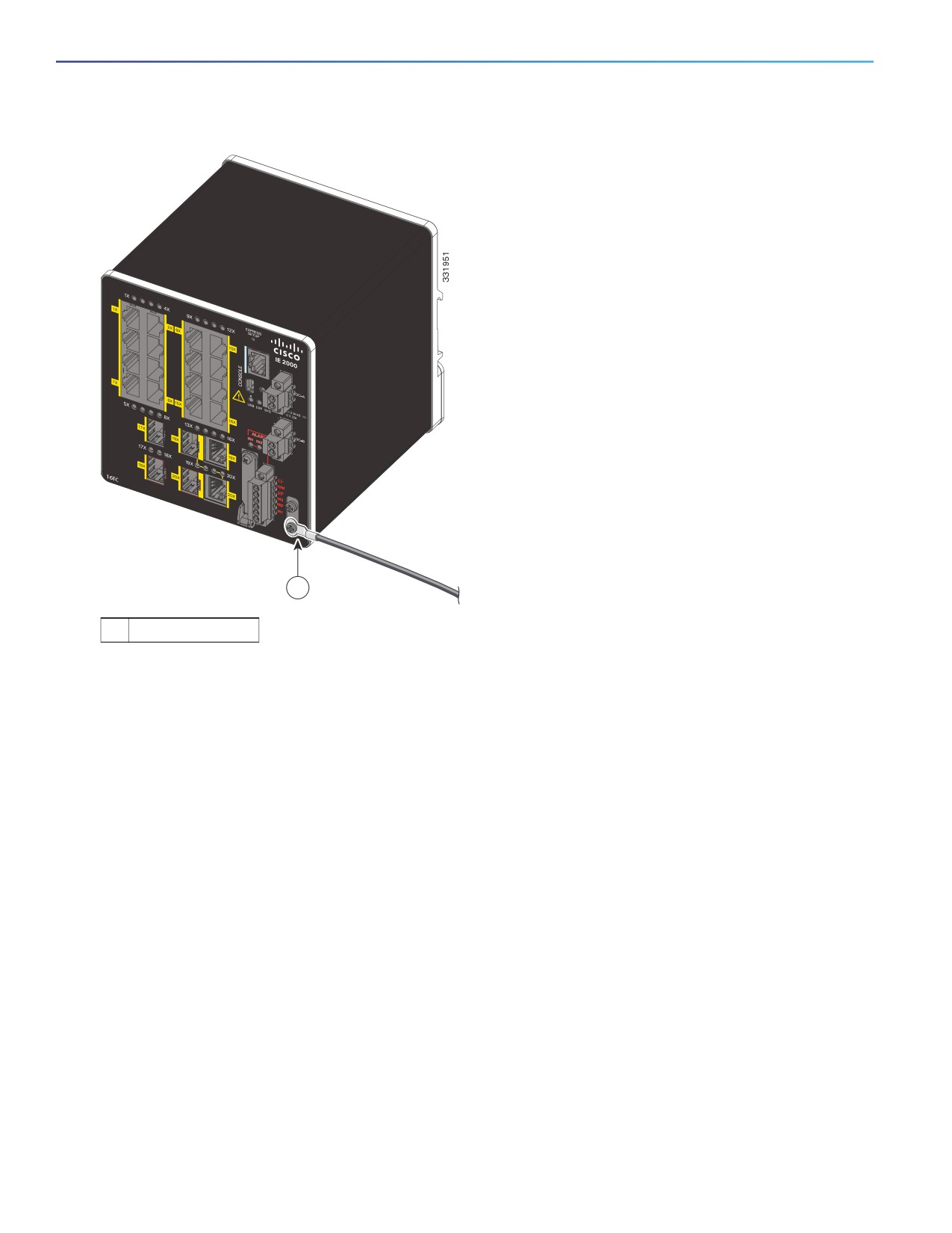
Figure 18
Installing the Ground-Lug Screw (Single Ring Terminal)
1
1
Ground cable
42
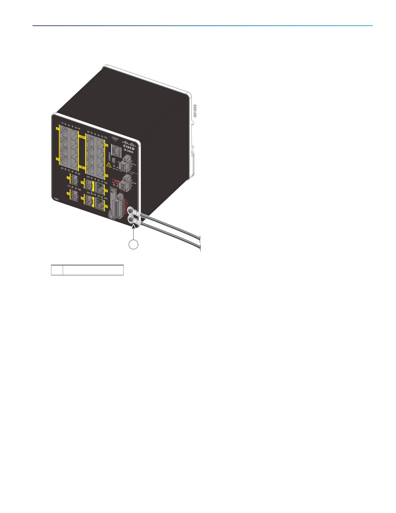
Figure 19
Installing the Ground-Lug Screws (Two Single Ring Terminals)
1
1
Ground cable
7. Attach the other end of the ground wire to a grounded bare metal surface, such as a ground bus, a grounded DIN
rail, or a grounded bare rack.
Connecting the Power Converter to an AC Power Source
These sections describe the steps required to connect the power converter to an AC power source:
Preparing the AC Power Connection, page 43
Connecting the AC Power Source to the Power Converter, page 44
Preparing the AC Power Connection
To connect the power converter to an AC power source, you need an AC power cord. Power cord connector types and
standards vary by country. Power-cord wiring color codes also vary by country. You must have a qualified electrician
select, prepare, and install the appropriate power cord to the power supply.
Use copper conductors only, rated at a minimum temperature of 167°F (75°C).
This section does not apply to PWR-IE50W-AC-IEC, which has pluggable IEC connector.
43
Connecting the AC Power Source to the Power Converter
Caution: AC power sources must be dedicated AC branch circuits. Each branch circuit must be protected by a dedicated
two-pole circuit breaker.
Caution: Do not turn on AC power until the wiring is secured.
1. Remove the plastic cover from the input power terminals and set it aside.
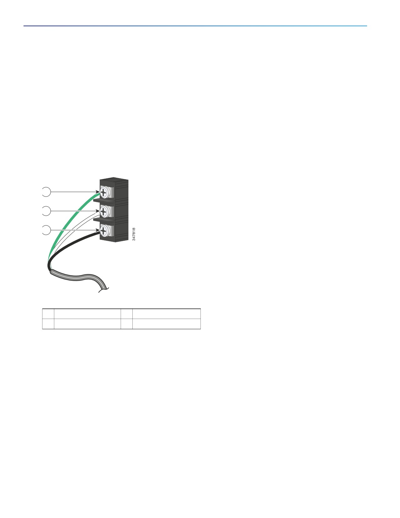
2. Insert the exposed ground wire lead into the power converter ground wire connection.
Ensure that only wire with insulation extends from the connector. See Figure 20 on page 44, item 1. Note that the position
of the power converter may vary on different switch models.
Figure 20
Connecting AC Power
1
2
3
1
Ground
3
AC line
2
AC neutral
3. Tighten the ground wire terminal block screw.
Note: Torque to 8 in.-lb, not to exceed 10 in-lb.
4. Insert the line and neutral wire leads into the terminal block line and neutral connections. See Figure 20 on page 44,
items 2 and 3.
Ensure that you cannot see any wire lead, and that only wire with insulation extends from the connectors.
5. Tighten the line and neutral terminal block screws to 8 in.-lb torque.
Note: Do not exceed 10 in-lb torque.
6. Replace the plastic cover over the terminal block.
7. Connect the other end of the wiring to your AC power source.
44
Connecting the Power Converter to a DC Power Source
You can also connect the power converter to a DC power source. Several power supplies can be used. Refer to Table 11
on page 39 for the appropriate DC input ratings.
Use copper conductors only, rated at a minimum temperature of 167°F (75°C).
1.
Measure a single length of stranded copper wire long enough to connect the power converter to the earth ground.
The wire color differs depending on country.
For connections from the power converter to earth ground, use shielded 18-AWG stranded copper wire, such as
Belden part number 9912 or the equivalent.
2.
Measure a length of twisted-pair copper wire long enough to connect the power converter to the DC power source.
For DC connections from the power converter to the DC source, use 18-AWG twisted-pair copper wire, such as
Belden part number 9344 or the equivalent.
3.
Using a 18-gauge wire-stripping tool, strip the ground wire and both ends of the twisted pair wires to 0.25 inch (6.3
mm) ± 0.02 inch (0.5 mm).
Note: Do not strip more than 0.27 inch (6.8 mm) of insulation from the wires. Stripping more than the recommended
amount of wire can leave exposed wire from the power and relay connector after installation.
4.
Connect one end of the stranded copper wire to a grounded bare metal surface, such as a ground bus, a grounded
DIN rail, or a grounded bare rack.
5.
Insert the other end of the exposed ground wire lead into the earth-ground wire connection on the power converter
terminal block.
Only wire with insulation should extend from the connection. See Figure 21 on page 46, item 1.
The position of the power converter varies on different switch models.
6.
Tighten the earth-ground wire connection terminal block screw to 8 in.-lb torque.
Note: Do not exceed 10 in-lb torque.
45
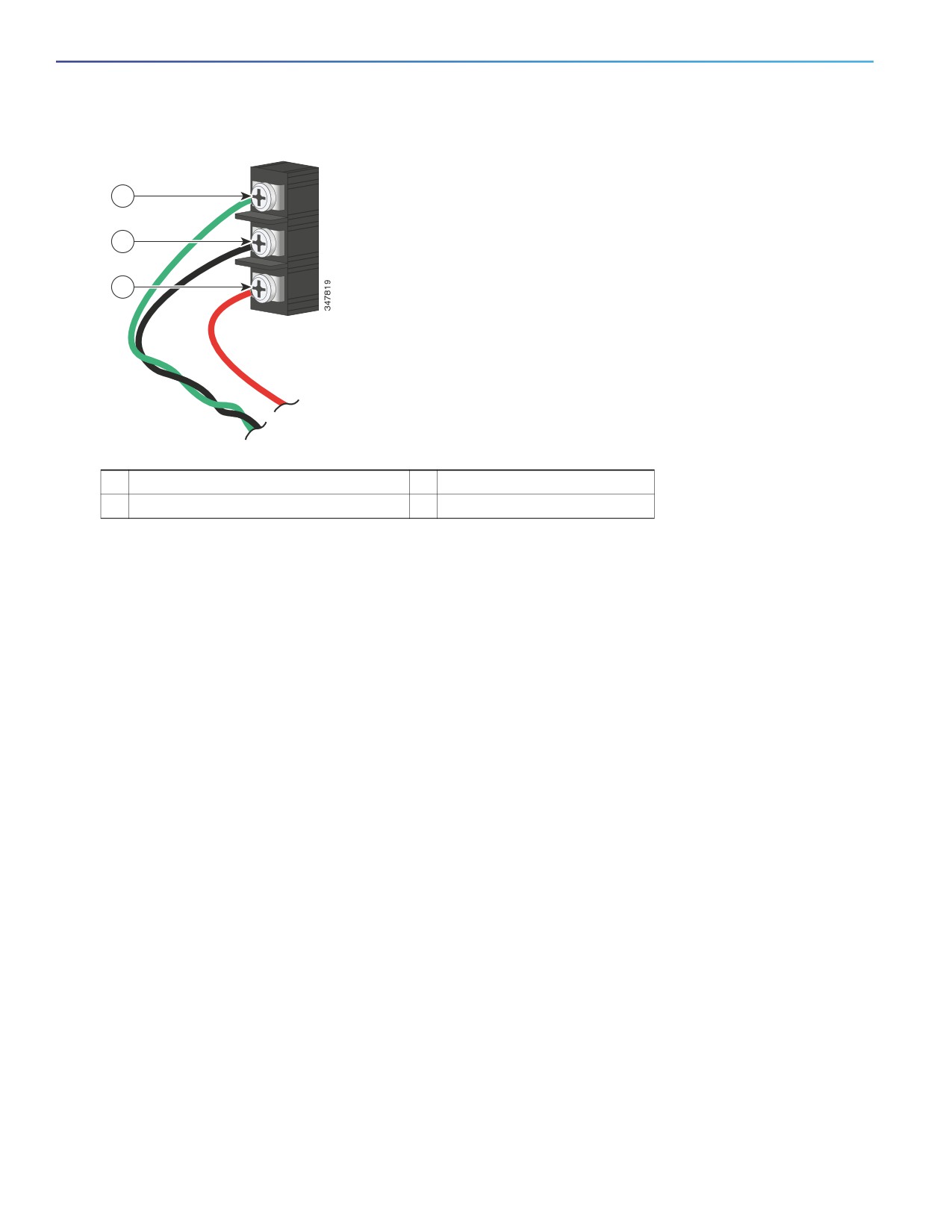
Figure 21
AC/DC Power Input Terminal Block Wire Connections to a DC Source
1
2
3
1
Earth ground wire connection
3
Positive DC connection
2
Return wire connection (to DC return)
Warning: An exposed wire lead from a DC-input power source can conduct harmful levels of electricity. Be sure that
no exposed portion of the DC-input power source wire extends from the power and relay connector. Statement 122
7. Insert the twisted-pair wire leads into the terminal block line and neutral connections.
8. Insert the wire (labeled number 1 in Figure 21 on page 46) lead into the neutral wire connection and the wire (labeled
number 2 in Figure 21 on page 46) lead into the line wire connection.
Ensure that only wire with insulation extends from the connectors. See Figure 21 on page 46.
9. Tighten the line and neutral terminal block screws to 8 in.-lb torque.
note: Do not exceed 10 in-lb torque.
10. Connect the red wire to the positive pole of the DC power source, and connect the black wire to the return pole.
Ensure that each pole has a current-limiting-type fuse rated to at least 600 VAC/DC (such as the KLKD Midget fuse).
Wiring the DC Power Source
Read these cautions and warnings before wiring the switch the DC power source.
Caution: This product is intended to be supplied by a Listed Class 2 power source marked with Class 2 and rated from
9.6V to 60VDC, 2.1A.
Warning: A readily accessible two-poled disconnect device must be incorporated in the fixed wiring.
Statement 1022
Warning: This product relies on the building’s installation for short-circuit (overcurrent) protection. Ensure that the
protective device is rated not greater than: 3A. Statement 1005
Warning: Installation of the equipment must comply with local and national electrical codes. Statement 1074
Warning: Before performing any of the following procedures, ensure that power is removed from the DC circuit.
Statement 1003
46
Warning: Only trained and qualified personnel should be allowed to install, replace, or service this equipment.
Statement 1030
Caution: For wire connections to the power and alarm connectors, you must use UL- and CSA-rated, style 1007 or 1569
twisted-pair copper appliance wiring material (AWM) wire (such as Belden part number 9318).
To wire the switch to a DC power source, follow these steps:
1. Locate the two power connectors on the switch front panel labeled DC-A and DC-B (see Figure 22 on page 47)
note: On the PoE-capable models of the switch, there is a third DC-input power connector on the switch front panel
labeled PoE. See Connecting Power to the Switch PoE DC-Input (Optional), page 52.
Figure 22
Power Connector
2. Identify the connector positive and return DC power connections.
The labels for power connectors DC-A and DC-B are on the switch panel as displayed in Table 12 on page 47.
Table 12
DC-A and DC-B Power Connector Labels
Label
Connection
+
Positive DC power connection
–
Return DC power connection
3. Measure two strands of twisted-pair copper wire (18-to-20 AWG) long enough to connect to the DC power source.
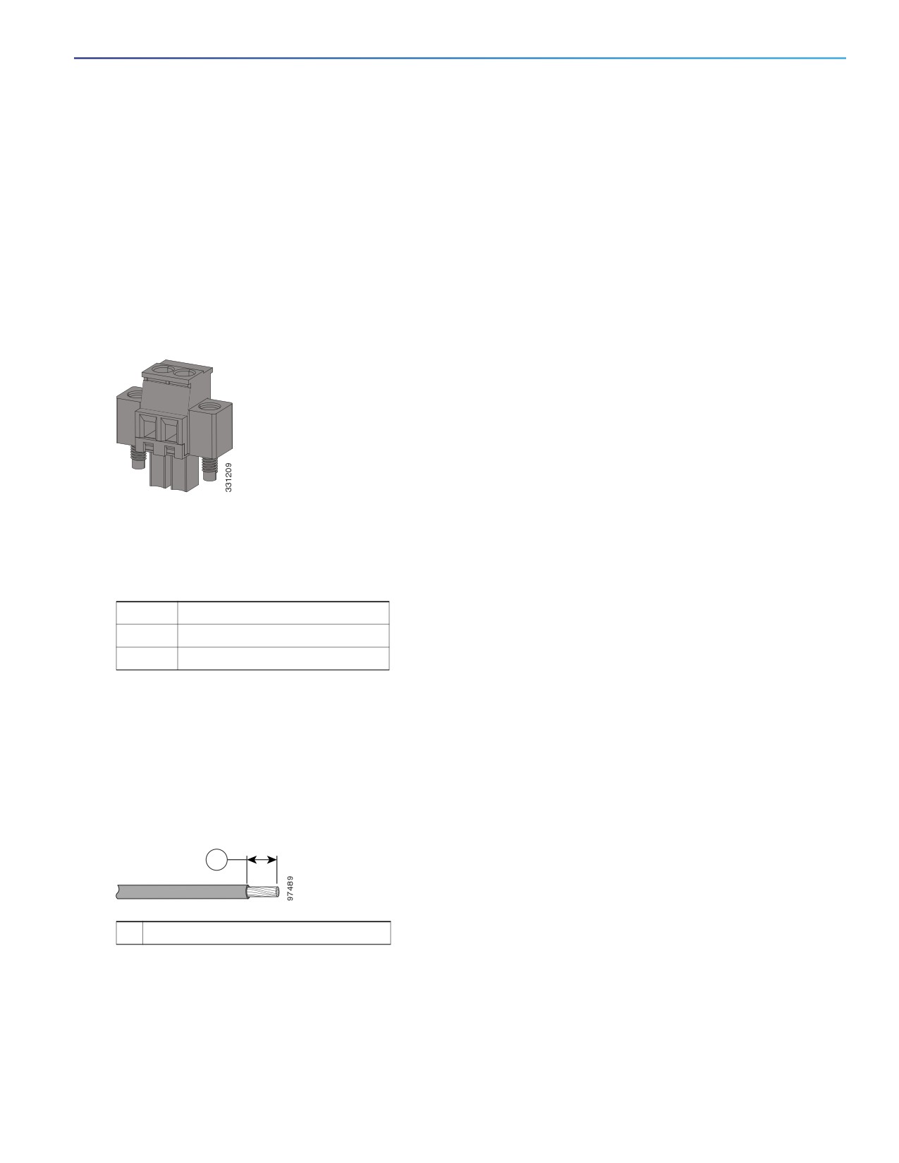
4. Using an 18-gauge wire-stripping tool, strip each of the two twisted pair wires coming from each DC-input power
source to 0.25 inch (6.3 mm) ± 0.02 inch (0.5 mm).
Note: Do not strip more than 0.27 inch (6.8 mm) of insulation from the wire. Stripping more than the recommended
amount of wire can leave exposed wire from the power connector after installation.
Figure 23
Stripping the Power Connection Wire
1
1
0.25 in. (6.3 mm) ± 0.02 in. (0.5 mm)
5. Remove the two captive screws that attach the power connector to the switch, and remove the power connector.
Remove both connectors if you are connecting to two power sources. See Figure 24 on page 48.
47
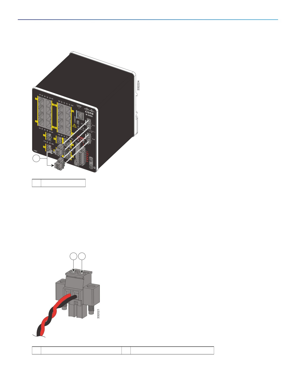
Figure 24
Removing the Power Connectors from the Switch
1
1
Power connectors
6. On the power connector, insert the exposed part of the positive wire into the connection labeled “+” and the exposed
part of the return wire into the connection labeled “-”. See Figure 25 on page 48.
Ensure that you cannot see any wire lead. Only wire with insulation should extend from the connector.
Warning: An exposed wire lead from a DC-input power source can conduct harmful levels of electricity. Be sure that
no exposed portion of the DC-input power source wire extends from the connector(s) or terminal block(s).
Statement 122
Figure 25
Inserting Wires in the Power Connector
1
2
1
Power source positive connection
2
Power source return connection
48
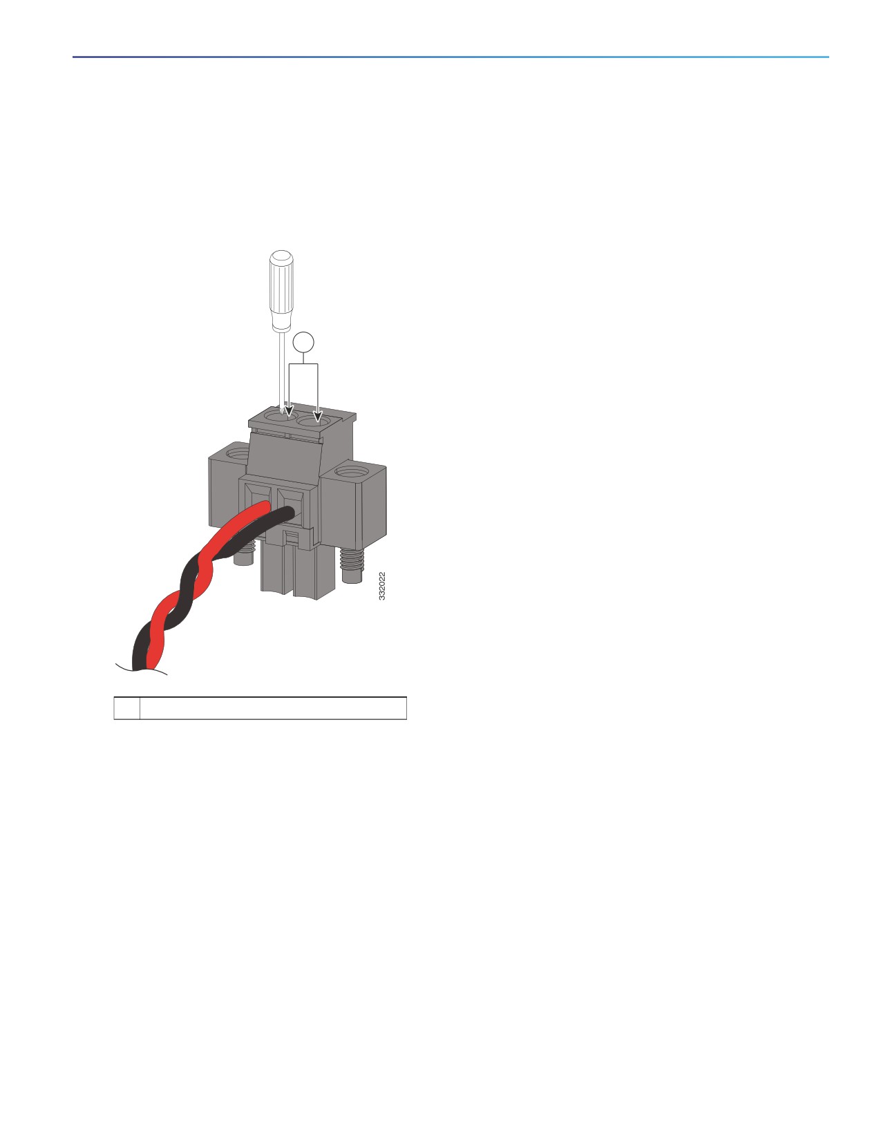
7. Use a ratcheting torque flathead screwdriver to torque the power connector captive screws (above the installed wire
leads) to 2 in-lb (0.23 N-m). See Figure 26 on page 49.
Note: Do not over-torque the power connector’s captive screws. The torque should not exceed 2 inch-lbs (0.23
N-m).
Figure 26
Torquing the Power Connector Captive Screws
1
1
Power connector captive screws
8. Connect the other end of the positive wire to the positive terminal on the DC power source, and connect the other
end of the return wire to the return terminal on the DC power source.
When you are testing the switch, one power connection is sufficient. If you are installing the switch and are using a
second power source, repeat steps 4 through 8 using the second power connector.
Figure 27 on page 50 shows the completed DC-input wiring on a power connector for a primary power source and
an optional secondary power source.
49
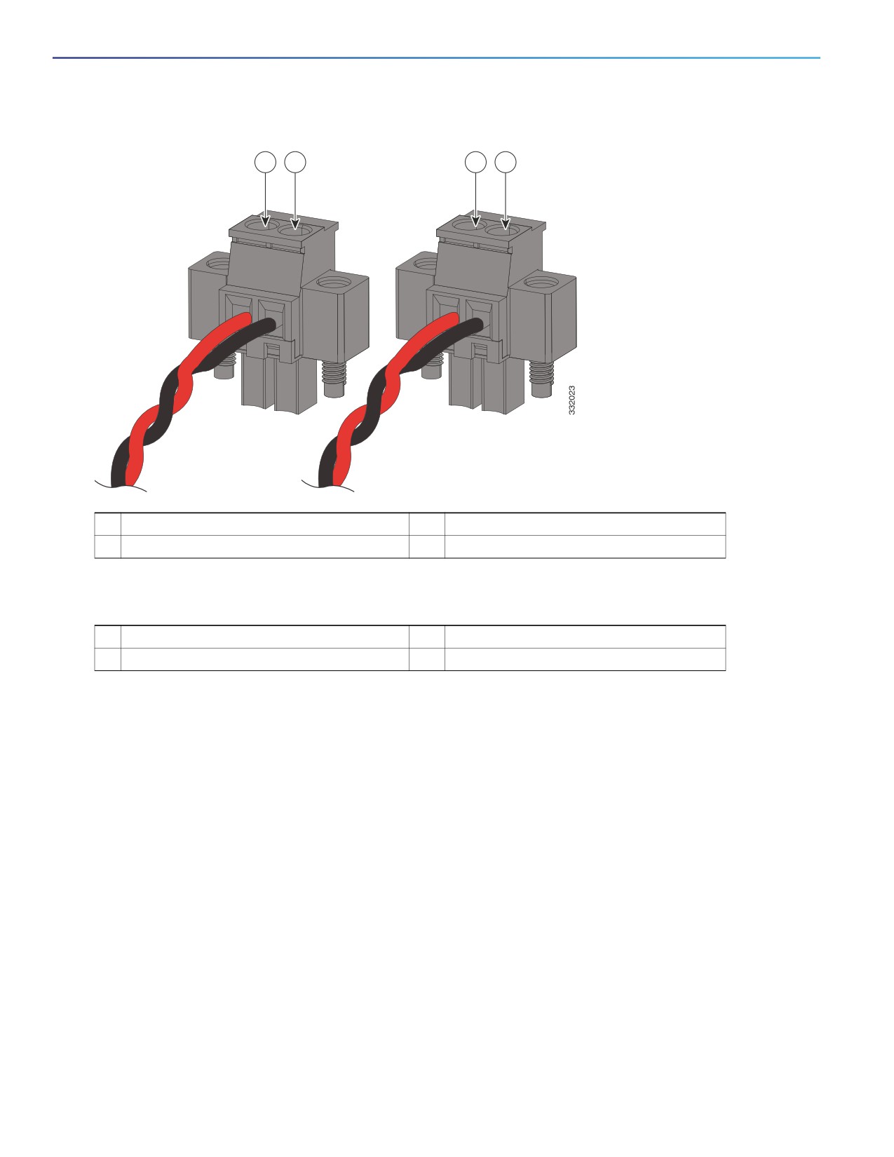
Figure 27
Completed DC Power Connections on the Power Connectors
1
2
3
4
1
Power source A positive connection
3
Power source B positive connection
2
Power source A return connection
4
Power source B return connection
For a -48 VDC power source, this table describes the wiring connections for Figure 27 on page 50.
1
Power source A return connection
3
Power source B return connection
2
Power source A -48 VDC connection
4
Power source B -48 VDC connection
Attaching the Power Connectors to the Switch
To attach the power connectors to the front panel of the switch, follow these steps:
1. Insert one power connector into the DC-A receptacle on the switch front panel, and the other into the DC-B
receptacle. See Figure 28 on page 51.
Warning: Failure to securely tighten the captive screws can result in an electrical arc if the connector is accidentally
removed. Statement 397
Warning: When you connect or disconnect the power and/or alarm connector with power applied, an electrical arc
can occur. This could cause an explosion in hazardous area installations. Be sure that all power is removed from the
switch and any other circuits. Be sure that power cannot be accidentally turned on or verify that the area is
nonhazardous before proceeding. Statement 1058
50
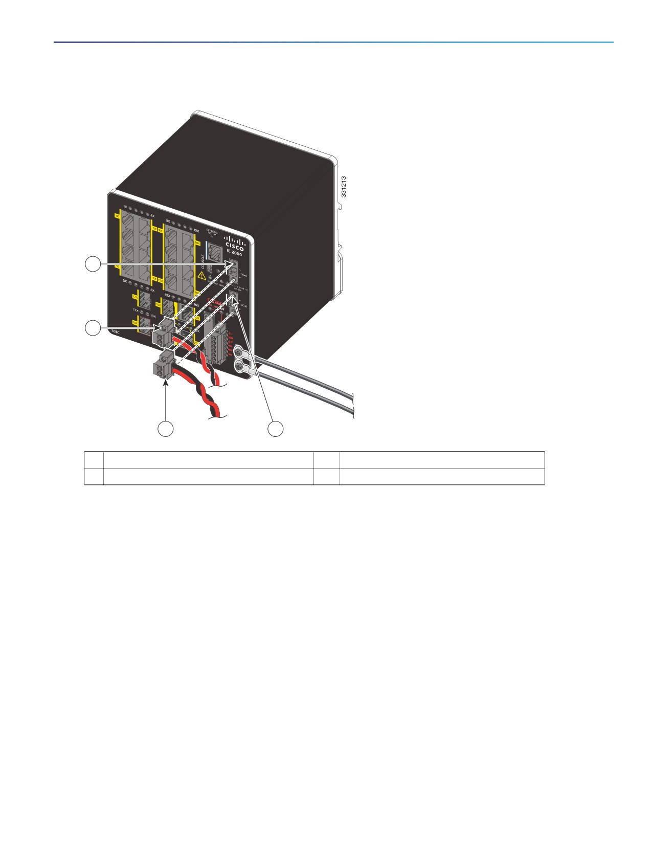
Figure 28
Attaching the Power Connectors to the Switch
2
1
3
4
1
DC-A power connector
3
DC-B power connector
2
DC-A power connection
4
DC-B power connection
51
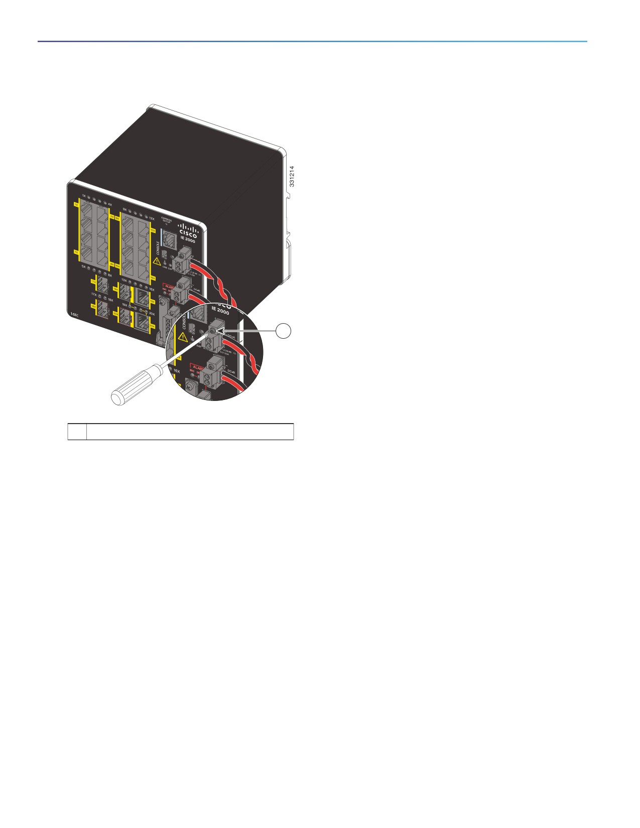
Figure 29
Connecting the Power Connectors to the Switch
1
1
DC-A power connector
upper captive screw
2. Use a ratcheting torque flathead screwdriver to tighten the captive screws on the sides of the power connectors.
When you are testing the switch, one power source is sufficient. If you are installing the switch and are using a second
power source, repeat this procedure for the second power connector (DC-B), which installs just below the primary power
connector (DC-A).
When you are installing the switch, secure the wires coming from the power connector so that they cannot be disturbed
by casual contact. For example, use tie wraps to secure the wires to the rack.
Connecting Power to the Switch PoE DC-Input (Optional)
This procedure is applicable only to the IE 2000 switch models that are PoE capable. If you have a PoE capable IE 2000
switch and do not plan on using PoE, you do not need to attach power to the PoE DC-input connector; the switch can
operate without the connection being made.
Figure 30 shows how a second power supply is connected to the switch to support PoE.PoE-capable Switch with PoE
Power Supply Module Connected.
52
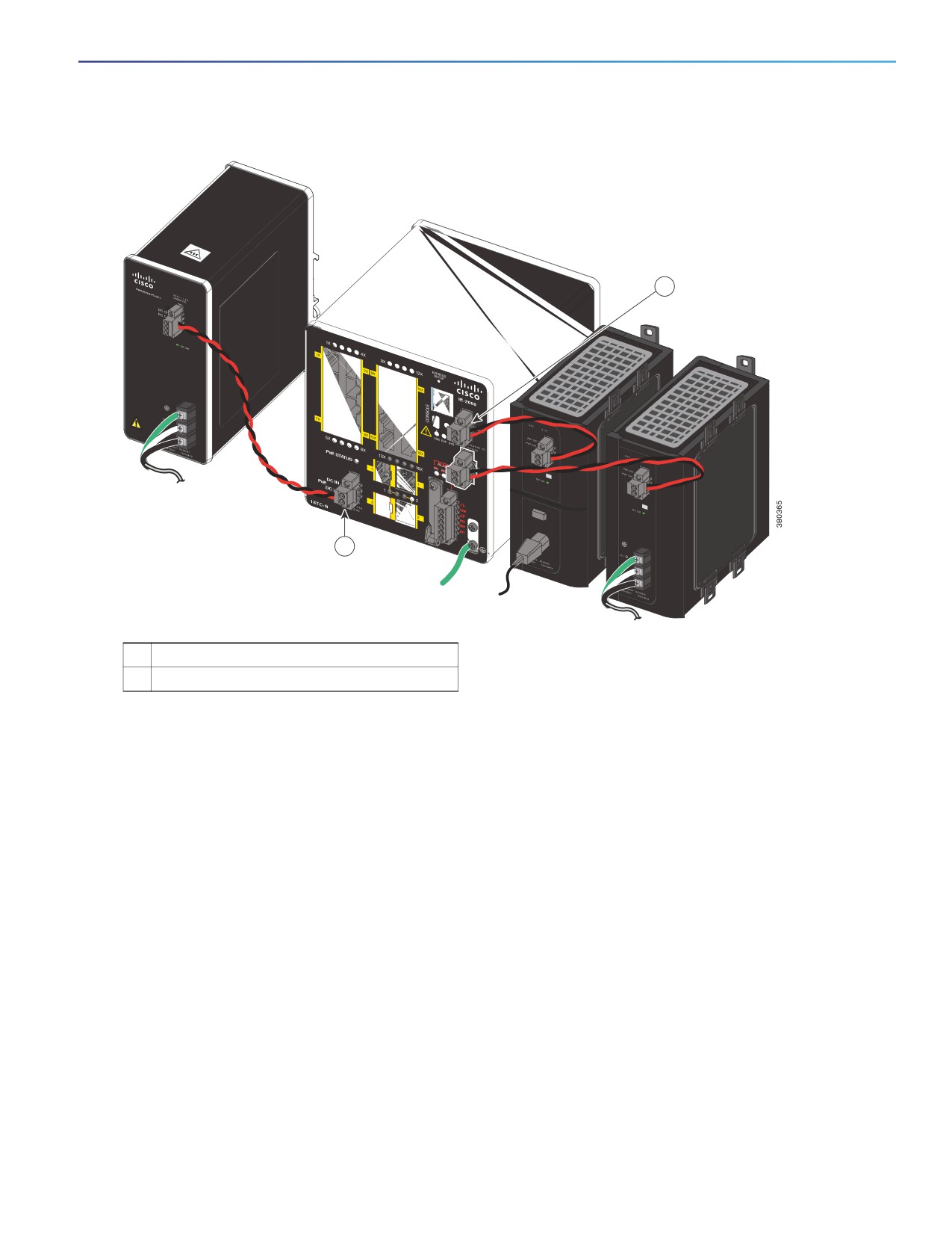
Figure 30
PoE-capable Switch with PoE Power Supply Module Connected
1
2
1
Power connector
2
PoE power connector
Warning: An exposed wire lead from a DC-input power source can conduct harmful levels of electricity. Be sure that
no exposed portion of the DC-input power source wire extends from the connector(s) or terminal block(s).
Statement 122
Caution: Do not over-torque the PoE power connector’s captive screws. The torque should not exceed 2 in-lb
(0.23 N-m).
Note: The input rating is 48/54VDC 2.5A.
53
1.
Verify that power is off to the DC circuit that you are going to attach to the switch PoE DC-input connector.
This can be either of the two power supplies (AC-input or DC-input) or site source DC.
As an added precaution, place the appropriate safety flag and lockout devices at the source power circuit
breaker, or place a piece of adhesive tape over the circuit breaker handle to prevent accidental power
restoration while you are working on the circuit.
2.
Locate the PoE DC-input power connector, which is labeled PoE, on the switch front panel.
3.
Loosen the power connector’s two screws and remove the plug portion of the connector from the switch.
4.
Measure two strands of twisted-pair copper wire (18 AWG (0.8 mm2) long enough to connect the switch to
the DC power source.
5.
Using a wire-stripping tool, strip each of the two twisted pair wires coming from each DC-input power source
to 0.25 inch (6.3 mm) ± 0.02 inch (0.5 mm).
Note: Do not strip more than 0.27 inch (6.8 mm) of insulation from the wire. Stripping more than the
recommended amount of wire can leave exposed wire from the power connector after installation.
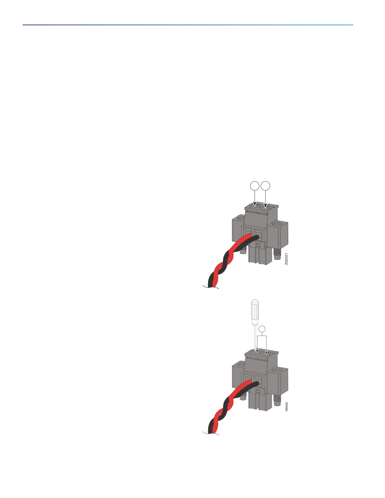
6.
Loosen the two captive screws on the PoE power
1—Power source
1
2
plug and insert the exposed part of the positive
positive connection
wire into the connection labeled “+” and the
2—Power source
exposed part of the return wire into the connection
return connection
labeled “-”.
Ensure that you cannot see any wire lead. Only
wire with insulation should extend from the
connector.
7.
Use a ratcheting torque flathead screwdriver to
1—Power
tighten the power connector captive screws
connector captive
(above the installed wire leads) to 2 in-lb
screws
(0.23 N-m).
1
54
8.
Connect the other end of the positive wire to the positive terminal on the DC power source, and connect the
other end of the return wire to the return terminal on the DC power source.
9.
Insert the wired power plug into the switch PoE power connector and tighten the two screws to secure the
plug.
Applying Power to the Power Converter
Move the circuit breaker for the AC outlet or the DC control circuit to the on position.
The LED on the power converter front panel is green when the unit is operating normally. The LED is off when the unit is
not powered or is not operating normally. After the power is connected, the switch automatically begins the power-on
self- test (POST), a series of tests that verifies that the switch functions properly.
Running Boot Fast
When the switch powers on, it automatically initiates a boot fast sequence. The boot fast sequence allows the switch to
boot up in less than 60 seconds. To test the switch, follow the steps in these sections:
Powering On the Switch, page 55
Verifying Boot Fast, page 55
Disconnecting Power, page 55
Powering On the Switch
To apply power to a switch that is directly connected to a DC power source, locate the circuit breaker on the panel board
that services the DC circuit, and switch the circuit breaker to the ON position.
Verifying Boot Fast
When you power on the switch, it automatically begins a boot fast sequence. The System LED blinks green as the Cisco
IOS software image loads. If the boot fast sequence fails, the System LED turns red.
Note: Boot fast failures are usually fatal. Call Cisco TAC immediately if your switch does not complete boot fast
successfully. See Obtaining Documentation and Submitting a Service Request.
Note: You can disable the boot fast and run POST by using the Cisco IOS CLI. See the Cisco IE 2000 Switch Software
Configuration Guide and the Cisco IE 2000 Switch Command Reference for more information.
Disconnecting Power
To disconnect power after successfully running boot fast, follow these steps:
1. Turn off power to the switch.
2. Disconnect the cables.
Installing the Switch
This section describes how to install the switch:
Installing the Switch on a DIN Rail, page 56
Removing the Switch from a DIN Rail, page 57
55
Installing the Switch on the Wall, page 58
Warning: This equipment is supplied as “open type” equipment. It must be mounted within an enclosure that is
suitably designed for those specific environmental conditions that will be present and appropriately designed to
prevent personal injury resulting from accessibility to live parts. The interior of the enclosure must be accessible
only by the use of a tool. The enclosure must meet IP 54 or NEMA type 4 minimum enclosure rating standards.
Statement 1063
Warning: When used in a Class I, Division 2, hazardous location, this equipment must be mounted in a suitable
enclosure with proper wiring method, for all power, input and output wiring, that complies with the governing
electrical codes and in accordance with the authority having jurisdiction over Class I, Division 2 installations.
Statement 1066
Caution: To prevent the switch from overheating, ensure these minimum clearances:
Top and bottom: 2.0 in. (50.8 mm)
Exposed side (not connected to the module): 2.0 in. (50.8 mm)
Front: 2.0 in. (50.8 mm)
Installing the Switch on a DIN Rail
The switch ships with a spring-loaded latch on the rear panel for a mounting on a DIN rail.
You can install the switch as a standalone device on the DIN rail or with the expansion modules already connected. You
must connect expansion modules to the switch before installing the switch on the DIN rail.
To attach the switch to a DIN rail, follow these steps:
1. Position the rear panel of the switch directly in front of the DIN rail, making sure that the DIN rail fits in the space
between the two hooks near the top of the switch and the spring-loaded latch near the bottom.
2. Holding the bottom of the switch away from the DIN rail, place the two hooks on the back of the switch over the top
of the DIN rail. See Figure 31 on page 57.
Caution: Do not stack any equipment on the switch.
56
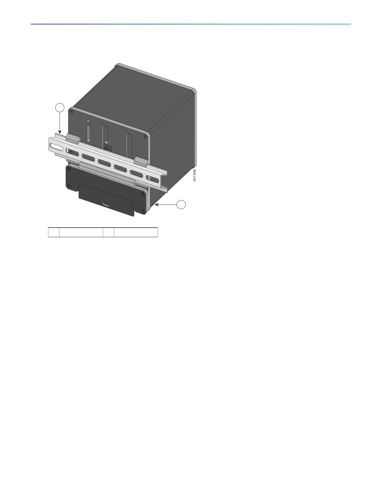
Figure 31
Position the Hooks Over the DIN Rail
1
2
1
DIN Rail
2
Switch
3. Push the switch toward the DIN rail to cause the spring-loaded latch at the bottom rear of the switch to move down,
and snap into place.
After the switch is mounted on the DIN rail, connect the power and alarm wires, as described in Connecting Alarm
Circuits, page 60.
For configuration instructions about the CLI setup program, see Configuring the Switch with the CLI-Based Setup
Program, page 101
For instructions on how to remove the switch from a DIN rail, see Removing the Switch from a DIN Rail, page 57.
Removing the Switch from a DIN Rail
To remove the switch from a DIN rail, follow these steps:
1. Ensure that power is removed from the switch, and disconnect all cables and connectors from the front panel of the
switch.
2. Insert a tool such as a flathead screwdriver in the slot at the bottom of the spring-loaded latch and use it to release
the latch from the DIN rail. See Figure 32 on page 58.
3. Pull the bottom of the switch away from the DIN rail, and lift the hooks off the top of the DIN rail. See Figure 32.
57

Figure 32
Releasing the Spring-Loaded Latch from the DIN Rail
1
1
Push latch down
4. Remove the switch from the DIN rail.
Installing the Switch on the Wall
Use the wall mount bracket to install the switch on the wall. According to the model of your IE2000 switch, choose one
of the following wall mount bracket model:
WALLMOUNT-IE2K-04
WALLMOUNT-IE2K-08
WALLMOUNT-IE2K-16
To attach the switch to a wall, follow these steps.
Warning: Read the wall-mounting instructions carefully before beginning installation. Failure to use the correct
hardware or to follow the correct procedures could result in a hazardous situation to people and damage to the
system. Statement 378
1. Remove four corner screws from the switch.
2. Allign the wall mount bracket to the rear panel of the switch. Thread the 4-40 screws provided with the wall mount
kit through each of the corner bores in the bracket and then into the switch rear cover. Tighten the screws, as shown
in Figure 33 on page 59.
3. Position the switch with mounted bracket against the wall in the desired location.
58
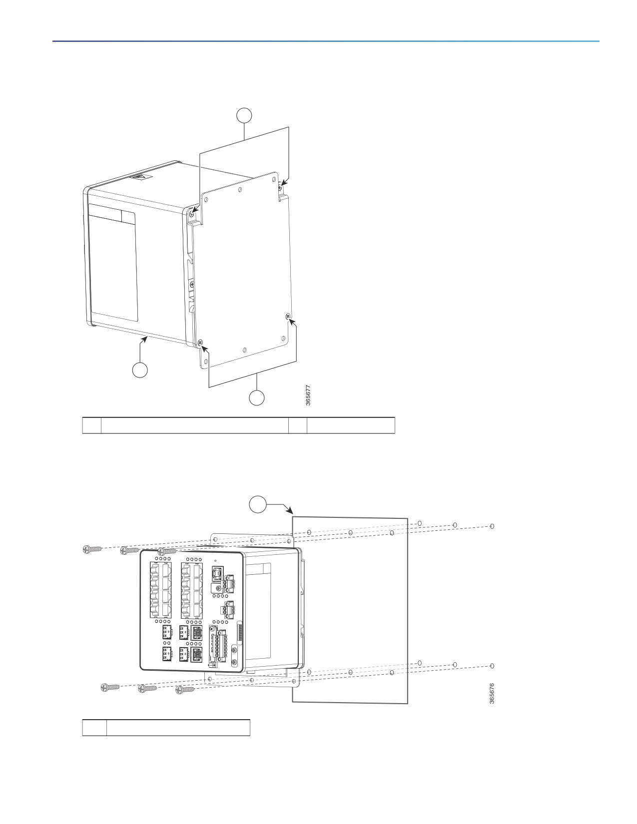
Figure 33
Wall Mount Bracket Installed to the Switch
1
2
1
1
4-40x5/8 Phillips Flat Head Screws
2
Switch
4. Place six screws and screw them into the wall, as shown in Figure 34 on page 59.
Figure 34
Wall Mount Bracket
1
1
Wall
59

After the switch is mounted on the wall, connect the power, alarm, and ground wires, as described in Wiring the DC
Power Source, Connecting Alarm Circuits, and Grounding the Switch.
For configuration instructions about the CLI setup program, see Configuring the Switch with the CLI-Based Setup
Program, page 101
Connecting Alarm Circuits
After the switch is installed, you are ready to connect the DC power and alarm connections.
Wiring the Protective Ground and DC Power for Alarm Circuits, page 60
Wiring the External Alarms, page 60
Wiring the Protective Ground and DC Power for Alarm Circuits
For instructions on grounding the switch and connecting the DC power, see Grounding the Switch, page 40.
Wiring the External Alarms
The switch has two alarm input and one alarm output relay circuits for external alarms. The alarm input circuits are
designed to sense if the alarm input is open or closed relative to the alarm input reference pin. Each alarm input can be
configured as an open or closed contact. The alarm output relay circuit has a normally open and a normally closed
contact.
Alarm signals are connected to the switch through the six-pin alarm connector. Three connections are dedicated to the
two alarm input circuits: alarm input 1, alarm input 2, and a reference ground. An alarm input and the reference ground
wiring connection are required to complete a single alarm input circuit. The three remaining connections are for the alarm
output circuit: a normally open output, a normally closed output, and a common signal. An alarm output and the common
wiring connection are required to complete a single alarm output circuit.
The labels for the alarm connector are on the switch panel and are displayed in Table 13 on page 60.
Table 13
Alarm Connector Labels (Top to Bottom)
Label
Connection
NO
Alarm Output Normally Open (NO) connection
COM
Alarm Output Common connection
NC
Alarm Output Normally Closed (NC) connection
IN2
Alarm Input 2
REF
Alarm Input Reference Ground connection
IN1
Alarm Input 1
Warning: Explosion Hazard—Do not connect or disconnect wiring while the field-side power is on; an electrical arc
can occur. This could cause an explosion in hazardous location installations. Be sure that power is removed or that
the area is nonhazardous before proceeding. Statement 1081
Caution: The input voltage source of the alarm output relay circuit must be an isolated source and limited to less than or
equal to 24 VDC, 1.0 A or 48 VDC, 0.5 A.
Note: Wire connections to the power and alarm connectors must be UL- and CSA-rated, style 1007 or 1569 twisted-pair
copper appliance wiring material (AWM) wire (such as Belden part number 9318).
60
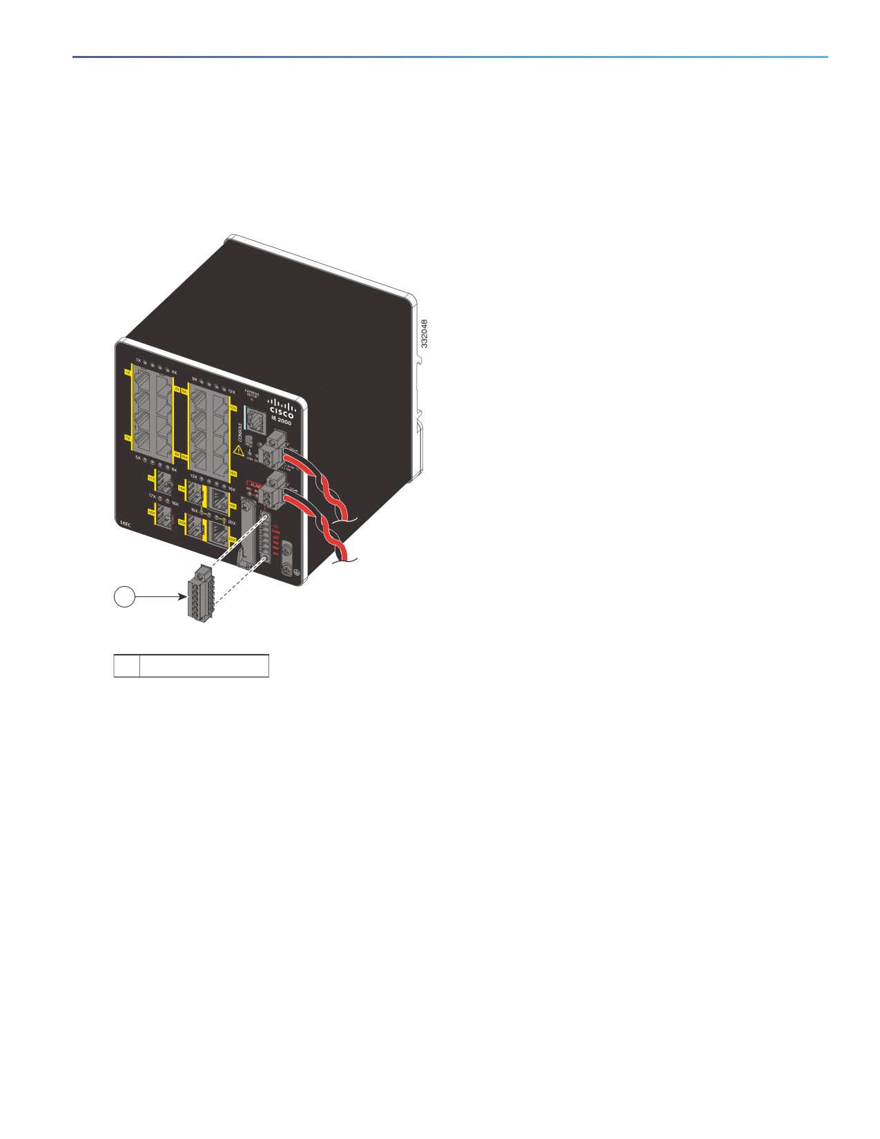
To wire the switch to an external alarm device, follow these steps:
1. Remove the captive screws that hold the alarm connector on the switch, and remove the connector from the switch
chassis.
Figure 35
Removing the Alarm Connector
1
1
Alarm connector
2. Measure two strands of twisted-pair wire (18-to-20 AWG) long enough to connect to the external alarm device.
You can choose between setting up an external alarm input or output circuit.
3. Use a wire stripper to remove the casing from both ends of each wire to 0.25 inch (6.3 mm) ± 0.02 inch (0.5 mm).
Do not strip more than 0.27 inch (6.8 mm) of insulation from the wires. Stripping more than the recommended
amount of wire can leave exposed wire from the alarm connector after installation.
4. Insert the exposed wires for the external alarm device into the connections based on an alarm input or output circuit
setup (see Table 13 on page 60).
For example, to wire an alarm input circuit, complete the IN1 and REF connections (See Figure 36 on page 62).
61
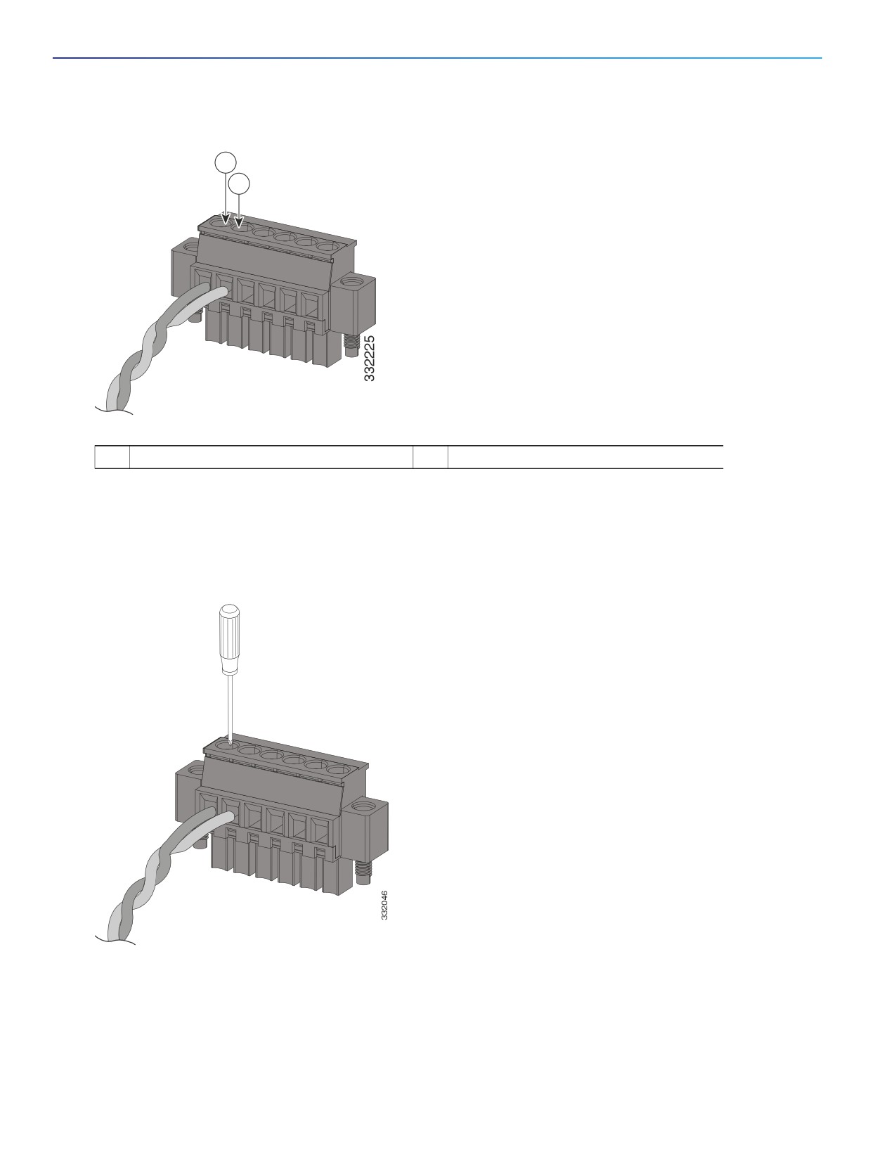
Figure 36
Inserting Wires into the Alarm Connector (Alarm Input Circuit)
1
2
1
IN1 - External device connection 1
2
REF - External device connection 2
5. Use a ratcheting torque flathead screwdriver to tighten the alarm connector captive screw (above the installed wire
leads) to 2 in-lb (0.23 N-m). (See Figure 37 on page 62.)
Note: Do not over-torque the power and alarm connectors’ captive screws. Do not exceed 2 inch-lbs (0.23 N-m) torque.
Figure 37
Securing the Alarm Connector Captive Screws
6. Repeat the above steps to insert the input and output wires of one additional external alarm device into the alarm
connector.
Figure 38 on page 63 shows the completed wiring for two external alarm devices. The first alarm device circuit is wired
as an alarm input circuit; the IN1 and REF connections complete the circuit. The second alarm device circuit is wired as
an alarm output circuit that works on a normally open contact basis; the NO and COM connections complete the circuit.
62
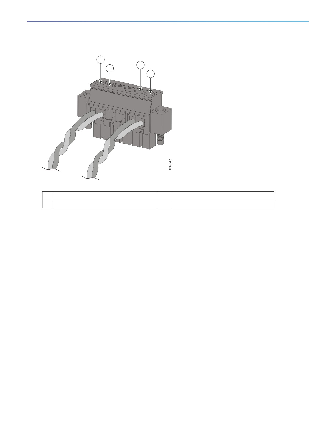
Figure 38
Completed Connections for Three External Alarm Devices on the Alarm Connector
1
3
2
4
1
IN1 wired connection
3
COM wired connection
2
REF wired connection
4
NO wired connection
Attaching the Alarm Connector to the Switch
Warning: Failure to securely tighten the captive screws can result in an electrical arc if the connector is accidentally
removed. Statement 397
Warning: When you connect or disconnect the power and/or alarm connector with power applied, an electrical arc
can occur. This could cause an explosion in hazardous area installations. Be sure that all power is removed from the
switch and any other circuits. Be sure that power cannot be accidentally turned on or verify that the area is
nonhazardous before proceeding. Statement 1058
To attach the alarm connector to the front panel of the switch:
1. Insert the alarm connector into the receptacle on the switch front panel. See Figure 39 on page 64.
63
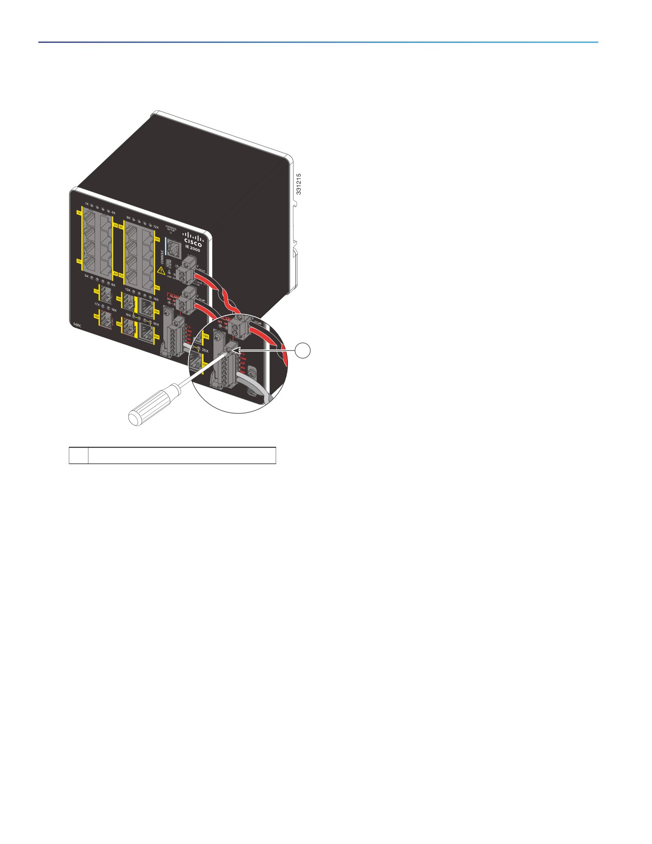
Figure 39
Connecting the Alarm Connector to the Switch
1
1
Alarm connector upper captive screw
2. Use a ratcheting torque flathead screwdriver to tighten the captive screws on the sides of the alarm connector.
Connecting Destination Ports
These section provide more information about connecting to the destination ports:
Connecting to 10/100 and 10/100/1000 Ports, page 64
Installing and Removing SFP Modules, page 66
Connecting to SFP Modules, page 69
Connecting to a Dual-Purpose Port, page 71
Connecting to 10/100 and 10/100/1000 Ports
The switch 10/100/1000 ports automatically configure themselves to operate at the speed of attached devices. If the
attached ports do not support autonegotiation, you can explicitly set the speed and duplex parameters. Connecting
devices that do not autonegotiate or that have their speed and duplex parameters manually set can reduce performance
or result in no linkage.
Warning: Do not connect or disconnect cables to the ports while power is applied to the switch or any device on
the network because an electrical arc can occur. This could cause an explosion in hazardous location installations.
Be sure that power is removed from the switch and cannot be accidentally be turned on, or verify that the area is
nonhazardous before proceeding. Statement 1070
64
To maximize performance, choose one of these methods for configuring the Ethernet ports:
Let the ports autonegotiate both speed and duplex.
Set the port speed and duplex parameters on both ends of the connection.
The models that support PoE provide up to four ports of either PoE (15.4 W per port; IEEE 802.3af) or PoE+ (30 W per
port; IEEE 802.3at), depending on the power source used. For more information, see Technical Specifications, page 81.
Caution: To prevent electrostatic-discharge (ESD) damage, follow standard board and component handling procedures.
To connect to 10BASE-T, 100BASE-TX or 1000BASE-T devices, follow these steps:
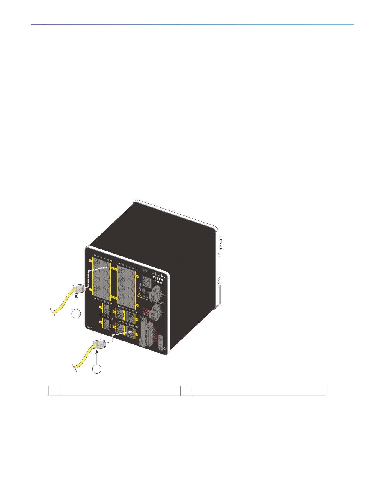
1. When connecting to workstations, servers, routers, and Cisco IP phones, connect a straight-through cable to an
RJ-45 connector on the front panel. See Figure 40 on page 65.
When connecting to 1000BASE-T-compatible devices, use a twisted four-pair, CAT5 or higher cable.
The auto-MDIX feature is enabled by default. For configuration information for this feature, see the Cisco IE 2000
Switch Software Configuration Guide or the Cisco IE 2000 Switch Command Reference.
Figure 40
Connecting to an Ethernet Port
1
2
1
10/100 port
2
10/100 or 10/100/100 port (depending on model)
2. Connect the other end of the cable to an RJ-45 connector on the other device.
The port LED turns on when both the switch and the connected device establish the link.
65
The port LED is amber while Spanning Tree Protocol (STP) discovers the topology and searches for loops. This can
take up to 30 seconds, and then the port LED turns green. If the port LED does not turn on:
— The device at the other end might not be turned on.
— There might be a cable problem or a problem with the adapter installed in the attached device. For solutions to
cabling problems, see Troubleshooting, page 75
3. Reconfigure and reboot the connected device if necessary.
4. Repeat Steps 1 through 3 to connect each device.
Installing and Removing SFP Modules
These sections describe how to install and remove SFP modules. SFP modules are inserted into SFP module slots on the
front of the switch. Field-replaceable SFP modules provide the uplink interfaces, send (TX) and receive (RX).
You can use any combination of rugged SFP modules. See Table 2 on page 19 for a list of supported modules. Each SFP
module must be of the same type as the SFP module on the other end of the cable, and the cable must not exceed the
stipulated cable length for reliable communications. See Table 2 on page 19 for cable stipulations for SFP module
connections.
Caution: When you use commercial SFP modules such as CWDM and 1000BX-U/D, reduce the maximum operating
temperature by 59°F (15°C). The minimum operating temperature is 32°F (0°C).
Caution: To prevent electrostatic-discharge (ESD) damage, follow standard board and component handling procedures.
Warning: Do not insert and remove SFP modules while power is on; an electrical arc can occur. This could cause an
explosion in hazardous location installations. Be sure that power is removed or the area is nonhazardous before
proceeding. Statement 1087
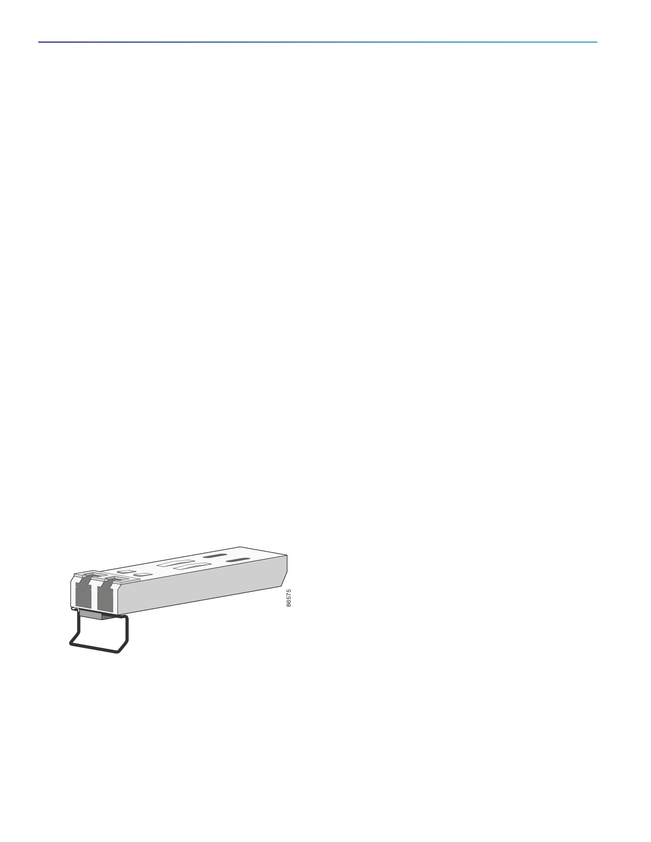
Figure 41 on page 66 shows an LC SFP module with a bale-clasp latch.
Caution: Do not install or remove the LC SFP module with fiber-optic cables attached because of potential damage to
the cables, the cable connector, or the optical interfaces in the SFP module. Disconnect all cables before removing or
installing an SFP module. Removing and installing an SFP module can shorten its useful life. Do not remove and insert
SFP modules more often than is absolutely necessary.
Figure 41
LC SFP Module with Open Bale-Clasp Latch
66
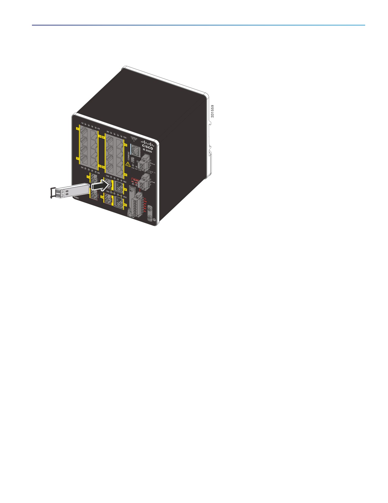
Figure 42
Installing an SFP Module into an SFP Module Slot
Installing LC SFP Modules
To insert an LC SFP module into the SFP module slot:
1. Attach an ESD-preventive wrist strap to your wrist and to a grounded bare metal surface.
2. Find the send (TX) and receive (RX) markings that identify the correct side of the SFP module.
On some SFP modules, the send and receive (TX and RX) markings might be replaced by arrows that show the
direction of the connection, either send or receive (TX or RX).
3. Align the SFP module sideways in front of the slot opening.
4. Insert the SFP module into the slot until the connector on the module snaps into place in the rear of the slot. See
Figure 42 on page 67.
5. Remove the dust plugs from the SFP module optical ports and store them for later use.
Caution: Do not remove the dust plugs from the SFP module port or the rubber caps from the fiber-optic cable until
you are ready to connect the cable. The plugs and caps protect the SFP module ports and cables from contamination
and ambient light.
6. Insert the LC cable connector into the SFP module.
Installing 1000BASE-T SFP Modules
The 1000BASE-T (copper) SFP transceiver, see Figure 43 on page 68, has a bale-clasp locking mechanism that secures
the transceiver in the module socket. An RJ-45 connector provides the transceiver's interface point to the network.
67
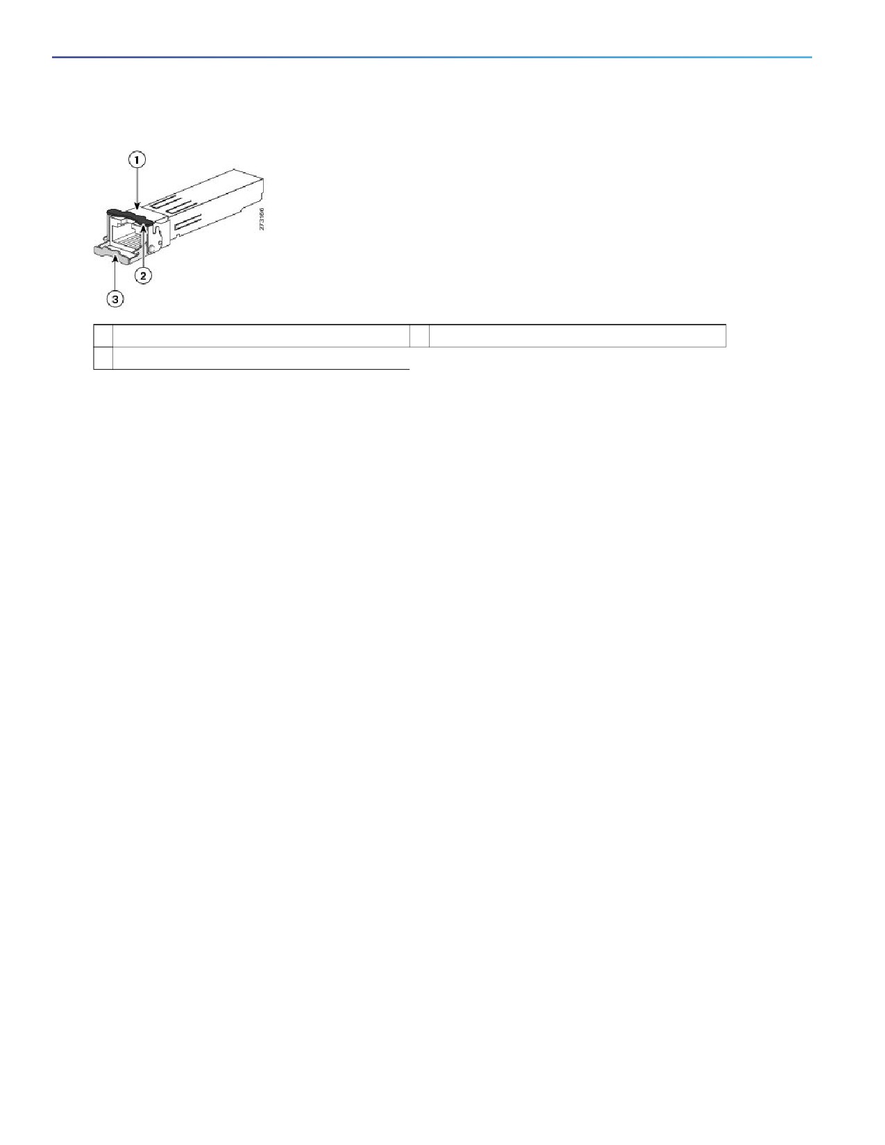
Figure 43
1000BASE-T SFP Transceiver
1
RJ-45 connector
3
Open bale-clasp latch (unlocked)
2
Closed bale-clasp latch mechanism (locked)
Caution: To comply with GR-1089 intrabuilding lightning immunity requirements, you must use grounded, shielded,
twisted-pair, CAT5 cabling.
When connecting to a 1000BASE-T-compatible server, workstation, or router, use four twisted-pair, straight-through
CAT5 cabling for the SFP transceiver port. When connecting to a 1000BASE-T-compatible switch or repeater, use four
twisted-pair, crossover CAT5 cabling.
To install a 1000BASE-T SFP transceiver:
1.
Attach an ESD-preventive wrist strap to your wrist and to the ESD ground connector on the chassis or to a properly
grounded bare metal surface.
Caution: To avoid ESD damage, handle the SFP by its sides; do not touch the connector pins.
2.
Remove the new 1000BASE-T SFP module from its protective packaging.
3.
Check the markings on the SFP transceiver to verify that you have the correct model for your network.
4.
Position the SFP transceiver in front of the port socket opening.
Note: Different Cisco devices have different SFP transceiver socket configurations. Your Cisco device might require
that the SFP transceiver be installed with the bale-clasp either in a latch-up or a latch-down orientation. Verify that
the SFP transceiver is oriented correctly when you position it in front of the port socket.
5.
With the bale-clasp closed (locked), slide the SFP transceiver into the socket until you feel it snap in place in the
socket. You may hear an audible click as the SFP transceiver latch engages in the socket (Figure 42 on page 67).
6.
Connect the network interface cable RJ-45 plug to the SFP RJ-45 connector.
7.
Observe the port status LED:
— Green indicates that the SFP transceiver and the target device established a link.
— Amber indicates that the port is discovering the network topology and searching for loops. This process takes
about 30 seconds, and then the LED turns green.
— Off indicates that the target device might not be turned on, there might be a cable problem, or there might be
a problem with the adapter installed in the target device. Refer to Troubleshooting, page 75 for solutions to
cabling problems.
68
Removing SFP Modules from SFP Module Slots
To remove an SFP module from a module receptacle:
1. Attach an ESD-preventive wrist strap to your wrist and to a grounded bare metal surface.
2. Disconnect the LC from the SFP module.
3. Insert a dust plug into the optical ports of the SFP module to keep the optical interfaces clean.
4. Unlock and remove the SFP module.
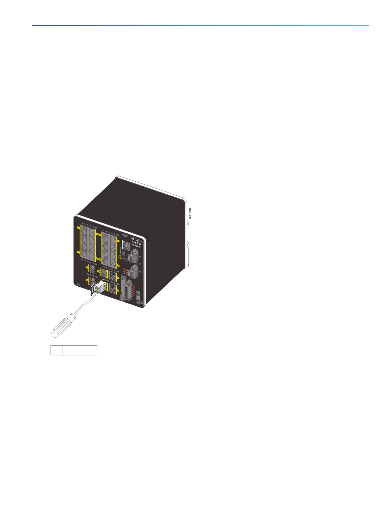
If the module has a bale-clasp latch, pull the bale out and down to eject the module. If the bale-clasp latch is obstructed
and you cannot use your index finger to open it, use a small, flat-blade screwdriver or other long, narrow instrument to
open the bale-clasp latch. See Figure 44 on page 69.
Figure 44
Opening a Bale-Clasp Latch on an SFP Module Using a Flat-Blade Screwdriver
1
Bale clasp
5. Grasp the SFP module between your thumb and index finger, and carefully remove it from the module slot.
6. Place the removed SFP module in an antistatic bag or other protective environment.
Connecting to SFP Modules
This section describes how to connect to a fiber-optic or copper SFP port. To connect to an RJ-45 Gigabit Ethernet port,
see Connecting to a Dual-Purpose Port, page 71. For instructions on how to install or remove an SFP module, see
Installing and Removing SFP Modules, page 66.
Warning: Class 1 laser product. Statement 1008
69