Kawasaki Robot Controller E Series. Installation and Connection Manual (2017) - page 1
CONTENTS
1.0
Safety ··································································································· 5
1.1
Precautions during Transportation and Storage ··················································· 5
1.2
Installation Environments of Robot Controller ··················································· 6
1.3
Precautions When Connecting the Harness ·····················································
11
1.4
Precautions When Connecting the External Power ············································
11
1.5
Warning Label for Electric Shock ································································
13
1.6
Battery and Fuse Use and Disposal·······························································
24
1.7
Safety Features ······················································································
26
1.8
Emergency Movement without Drive Power ···················································
27
2.0
Workflow - Robot Controller Installation and Connection ···································
33
3.0
Appearance and Specification of Robot Controller ············································
35
3.1
Controller Appearance ·············································································
35
3.2
Teach Pendant Appearance ········································································
61
3.3
Controller Specification ············································································
62
4.0
Transportation of Robot Controller·······························································
69
4.1
By Crane Lifting (E1x, E2x, E3x, E4x)··························································
69
4.2
By Caster (E1x, E2x, E3x, E4x) ··································································
70
4.3
By Forklift Truck (E1x, E3x, E4x) ·······························································
71
4.4
By Two Persons (E7x, E9x) ·······································································
72
5.0
Arrangement of Robot Controller ································································
73
5.1
Arrangement of E1x/E2x/E3x/E4x Controllers·················································
73
5.2
Arrangement of E7x/E9x Controllers ····························································
76
6.0
Connection Instructions ············································································
79
6.1
Connection between Controller and Robot ······················································
79
6.2
Connection between Controller and Teach Pendant ···········································
91
7.0
Connection of External Power ····································································
92
7.1
Change of External Power Input Voltage (only for E1x/E3x Controllers with Optional
Transformer) ························································································ 100
3
8.0
Connection of Peripheral Control Equipment·················································· 101
8.1
Connection Instructions ··········································································· 105
8.2
Connection of General Purpose Signal·························································· 106
8.3
Connection of Hardware Dedicated Signal····················································· 109
8.4
Connection of Personal Computer ······························································· 109
8.5
Connection of RS-232C Serial Signal (Option) ··············································· 109
8.6
Connection of Ethernet Communication Signal (Option) ···································· 109
8.7
Connection of Fieldbus (Option) ································································ 110
8.8
Connection of Sensors/Valves on Arm (Option) ·············································· 110
8.9
Cooler Drain Piping of E28 Controller ························································· 110
8.9.1
Precautions to be Taken during Drain Piping ·················································· 111
4
1. Safety
1.0 SAFETY
This chapter only describes safety precautions during installation and connection of the controller.
For all other safety matters, refer to the “Safety Manual”, a separate-volume.
1.1 PRECAUTIONS DURING TRANSPORTATION AND STORAGE
To transport the Kawasaki Robot Controller to its installation place, strictly observe the following
cautions while carrying out the transportation and installation work.
[ NOTE ]
The installation shall be made by qualified installation
personnel and should conform to all national and local codes.
!
WARNING
1. When transporting a controller with a crane or a forklift, never support
the controller manually.
2. During the transportation, stay out from under the lifted controller.
!
CAUTION
1. Since the controller is composed of precision parts, be careful not to
apply excessive shocks or vibrations to the controller during
transportation.
2. To carry out smooth and safe installation, remove all obstacles before
installing a controller. Clear a passage for the transportation of
controller before using a crane or forklift.
3. When transporting or storing a controller:
(1) keep the ambient temperature within the range of minus 10 - 60C
(2) keep the relative humidity within the range of 35 - 85% RH
(Non condensing)
(3) keep free from excessively large shock and vibration.
5
1. Safety
1.2 INSTALLATION ENVIRONMENTS OF ROBOT CONTROLLER
Install the controller in a site that satisfies all the following environmental conditions:
1. Ambient temperature during operation: within 0 - 45 C or within 0 - 40 C when placing E7x
controller vertically and E91 controller
2. Relative humidity: 35 - 85 %RH (Non condensing)
3. Altitude: up to 1000 meters above mean sea level
4. The following environmental conditions should be satisfied for dust, smoke, water, etc.
(Pollution degree and degrees of protection (IPxx) are specified by IEC60664-1 and IEC60529,
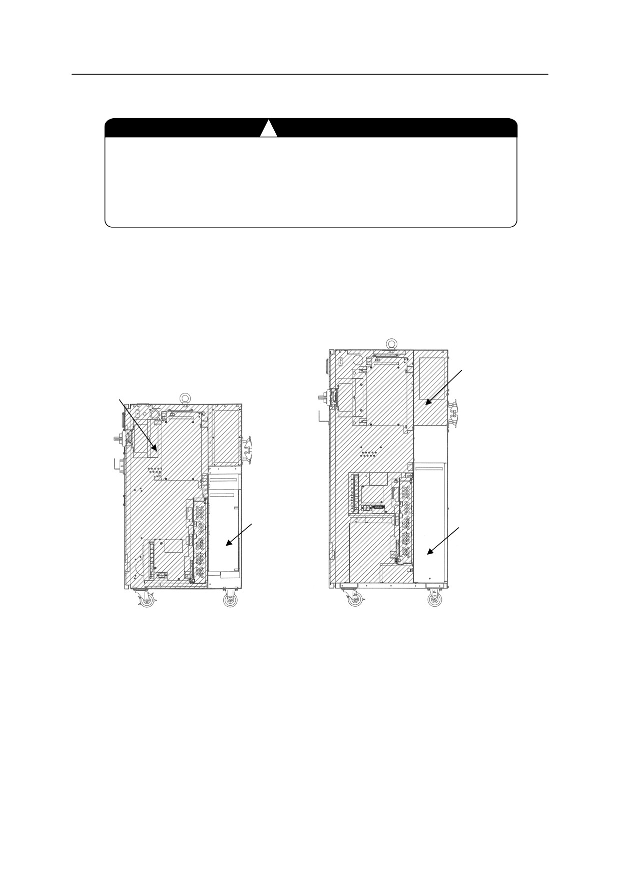
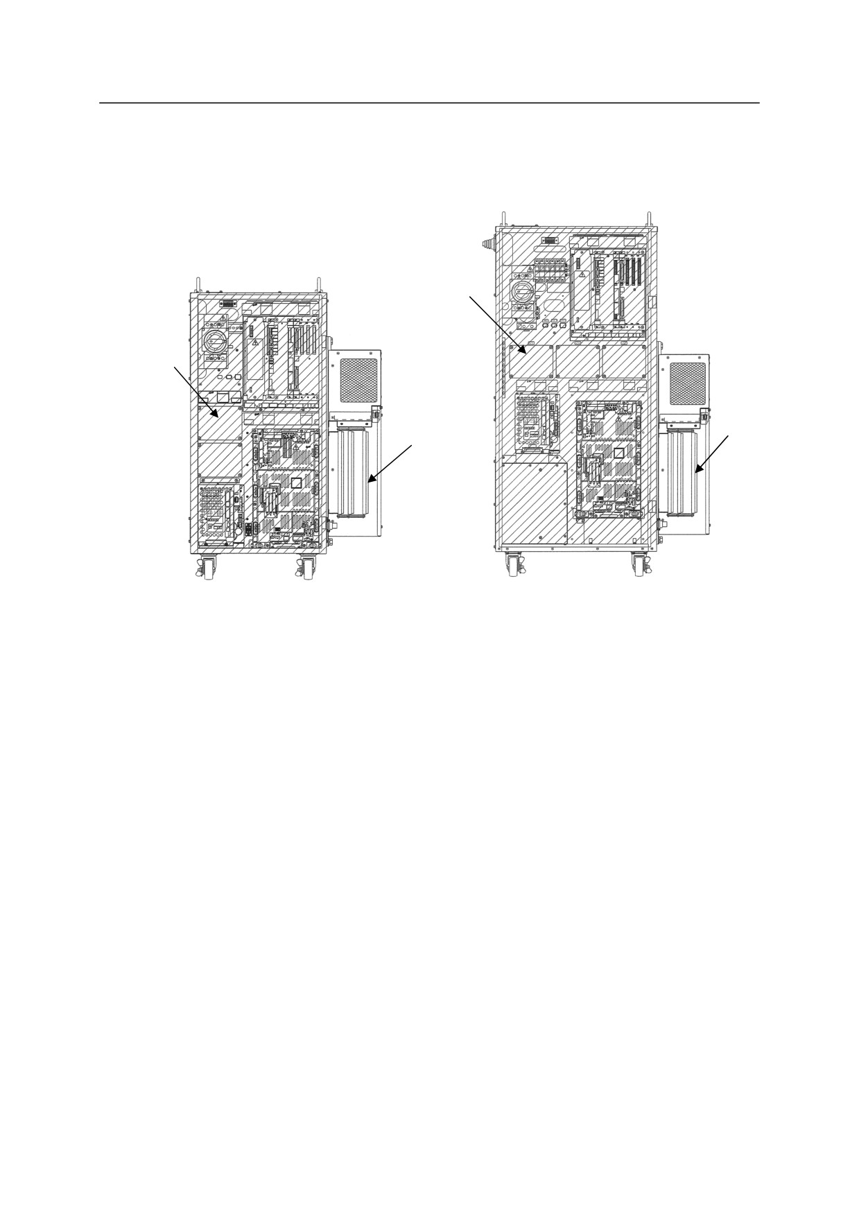
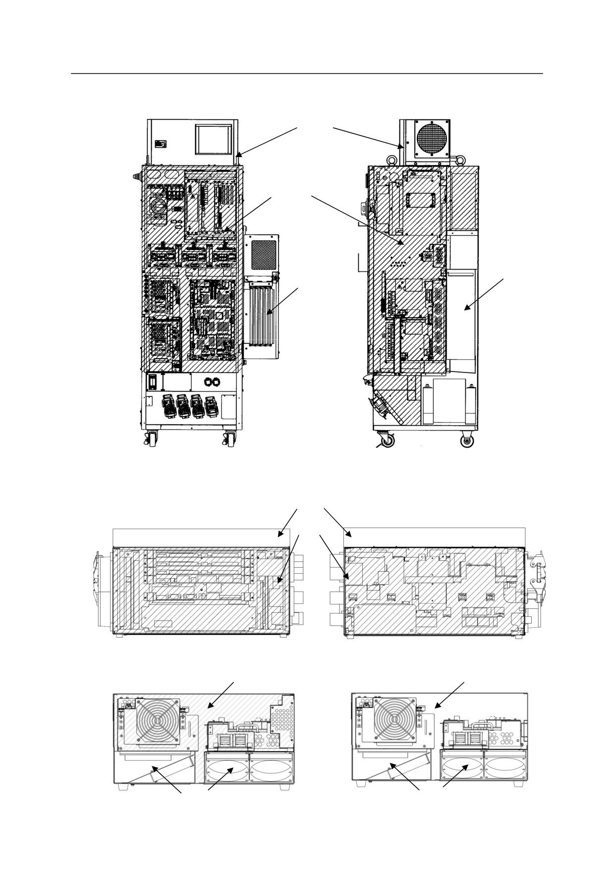
respectively. See figures on the next pages for the degrees of protection in each controller.)
The resistance to oil may not sufficient, so do not use the controller under the condition where
the controller gets oil on it or oil mist floats. If the controller is used under the condition
where there are water and oil around the controller, take measures so that the controller does
not get water and oil.
E1x/E2x/E3x/E4x/E7x/E91: Pollution degree: 3 or below, IP53/54 (Protective against entry of
dust into the controller which causes the loss of controller function and water droplets.)
E94/E97: Pollution degree: 2 or below, IP20, without dew condensation (Not protective against
objects which are thinner than fingers though it is impossible to insert fingers, entry of
electricity-conducting foreign substances such as metal powder, foreign substances which
conducts electricity by moisture, and water.)
!
CAUTION
When E94/E97 controller is used under the environmental condition with the pollution
degree of 3 or above, the use of optional enclosed structure (IP54) is required.
!
CAUTION
When installing the controller in the environment where metal dust, etc. is generated
in robot application to works shown below, mount fan filter prepared as option
(E1x/E2x/E3x/E4x controllers). For E91 controller (without optional filter) and
E94/E97 controllers (takes the air into the controller), they cannot be installed with
the following environment because air is taken into the controllers.
1. Metal workpiece polishing
2. Polished metal workpiece handling
3. Metal workpiece deburring
4. Deburred metal workpiece handling
5. Metal workpiece shotblasting
6. Aluminum package cutting (Cutting powder is generated.)
7. Other processing works where metal dust, etc. is generated.
6
1. Safety
5. Free from electrical noise interference.
(Controller external power noise: 1 kV/1 s or less)
!
CAUTION
If the controller is installed near equipment that generates a lot of electrical
noise, be sure to provide appropriate surge killers around that equipment.
Noise producing equipment includes: induction motors, electromagnetic
brakes, solenoids, or contact equipment, etc.
Degrees of protection in each controller
E10/E12/E13/E14
E30/E32/E33/E34
E40/E42/E43/E44
IP54
E20/E22/E23/E24
IP53
IP22
IP22
Right side view
Right side view
7
1. Safety
Controller with added regeneration resistors
E13/E14(MD)/E33/E34(MD)/E43/E44(MD)
Controller with added regeneration resistors
E23/E24(MD)
IP54
IP53
IP22
IP22
Front view (without door)
Front view (without door)
8
1. Safety
E28
IP22
IP54
IP22
IP22
Front view (without door)
Right side view
E70/E71/E73/E74/E76/E77
IP20
IP54
Left side view
Right side view
E91
E94/E97
IP54
IP20
IP20
IP20
9
1. Safety
6. Free from flammable and/or corrosive liquid and gas.
7. Free from excessively strong vibration.
8. Place where power is supplied within specifications.
9. Place where dedicated earthing is provided. (100 or less)
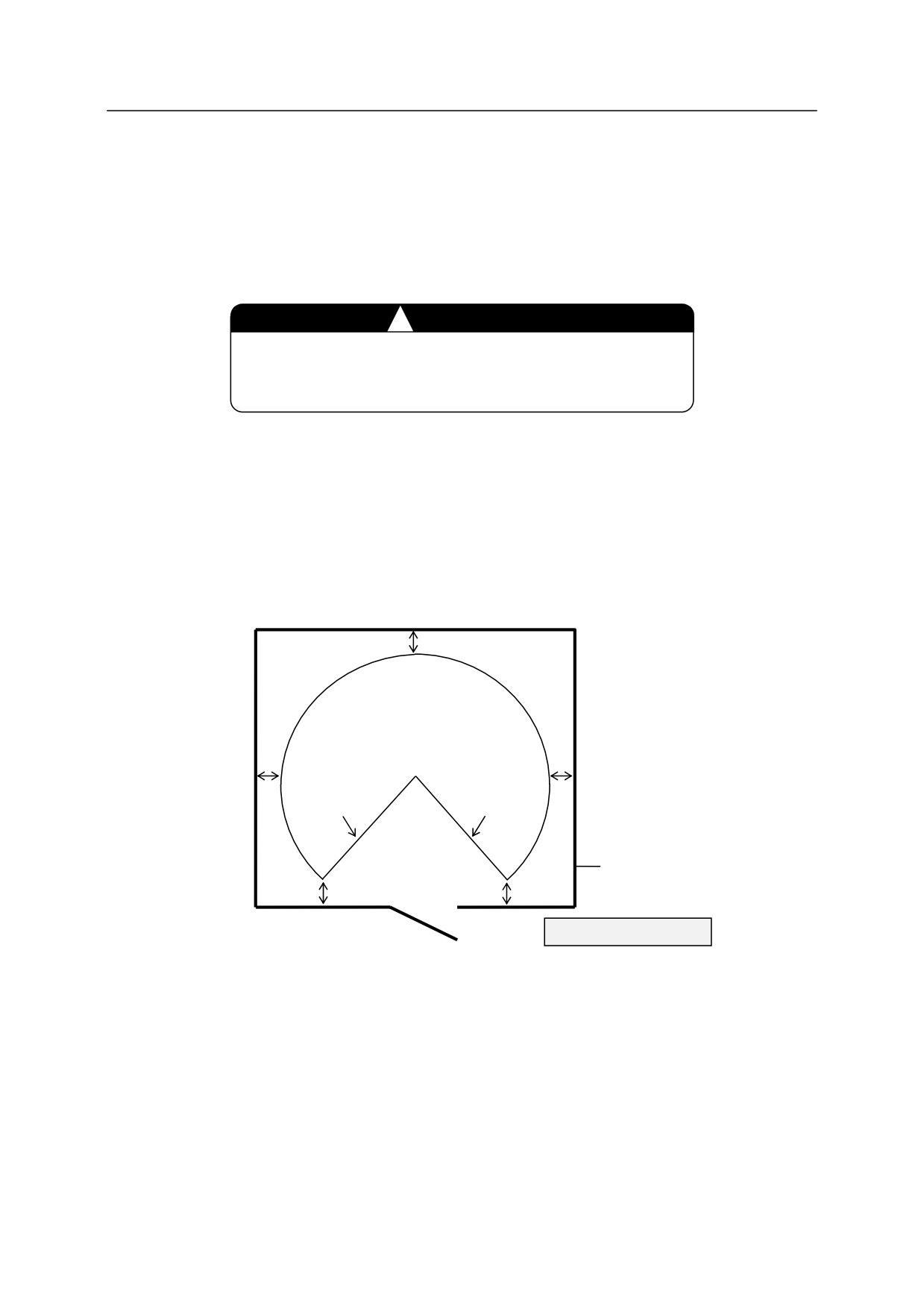
10. Outside the safety fence with margin (min. 1 m) from the motion range of robot arm (with
tools and workpieces).
!
CAUTION
The controller shall not be located inside of the robot’s
motion range/workcell/safety fence.
In addition, ensure the followings:
y Enough space for easy access to the controller during maintenance
y Installing an entrance gate with a safety plug to the safety fence
y Referring the requirements established in each region for details of the safety fence
(e.g. ISO13852-13855, ISO14119-14120, JISB9707-9708, JISB9710-9711,
JISB9715-9716)
Approx. 1 m
Motion range of robot arm
(tool and workpiece included)
Approx. 1 m
Approx. 1 m
Mechanical
Mechanical
stopper
stopper
Safety fence
Approx.
Approx.
1 m
1 m
Controller
Gate with safety plug
10
1. Safety
1.3 PRECAUTIONS WHEN CONNECTING THE HARNESS
Strictly observe the following precautions when connecting the robot arm with the robot
controller.
!
WARNING
In order to prevent accidents caused by electric shock, do not connect the
external power until connections between the robot arm and robot
controller are complete.
!
CAUTION
1. Be careful when connecting the harnesses. Be sure to use the correct
harnesses. Using an incorrect harness, or forcing or misconnecting the
harness may damage connectors or cause a break in the electrical
system.
2. Prevent people or equipment (forklift etc.) from stepping on or riding
over the signal and motor harnesses. Otherwise, the harness may
become damaged or the electrical system may break.
3. Separate the harnesses from any nearby high voltage lines (min. 1 m
apart). Do not bundle or run the harnesses in parallel with other
power lines. Otherwise, the noise generated from power lines will
cause malfunctions.
4. Even when the harnesses are long, do not bundle them winded or
bended. Bundling the harness causes the heat to build up in the
harness, resulting in over-heat and furthermore may cause fire.
1.4
PRECAUTIONS WHEN CONNECTING THE EXTERNAL POWER
Strictly observe the following precautions when connecting the external power.
!
DANGER
Before beginning the connection work, confirm that the external power supply
for the controller is cut off at the source. To prevent external power from being
turned ON accidentally, tag the breaker and indicate clearly that work is in
progress. Or, assign a supervisor in front of the breaker until all the connections