Cisco Industrial Ethernet 4000, 4010 and 5000 Switch Software. Configuration Guide (2022) - page 38

Working with the Cisco IOS File System, Configuration Files, and Software Images
Working with Software Images
Table 69
info File Description (continued)
Field
Description
total_image_file_size
Specifies the size of all the images (the Cisco IOS image and the web management files) in the
tar file, which is an approximate measure of how much flash memory is required to hold them.
image_feature
Describes the core functionality of the image.
image_min_dram
Specifies the minimum amount of DRAM needed to run this image.
image_family
Describes the family of products on which the software can be installed.
Copying Image Files By Using TFTP
You can download a switch image from a TFTP server or upload the image from the switch to a TFTP server.
You download a switch image file from a server to upgrade the switch software. You can overwrite the current image with
the new one or keep the current image after a download.
You upload a switch image file to a server for backup purposes; this uploaded image can be used for future downloads
to the same or another switch of the same type.
Note: Instead of using the copy privileged EXEC command or the archive tar privileged EXEC command, we recommend
using the archive download-sw and archive upload-sw privileged EXEC commands to download and upload software
image files.
Preparing to Download or Upload an Image File By Using TFTP
Before you begin downloading or uploading an image file by using TFTP, do these tasks:
Ensure that the workstation acting as the TFTP server is properly configured. On a Sun workstation, make sure that
the /etc/inetd.conf file contains this line:
tftp dgram udp wait root /usr/etc/in.tftpd in.tftpd -p -s /tftpboot
Make sure that the /etc/services file contains this line:
tftp 69/udp
You must restart the inetd daemon after modifying the /etc/inetd.conf and /etc/services files. To restart the
daemon, either stop the inetd process and restart it, or enter a fastboot command (on the SunOS 4.x) or a reboot
command (on Solaris 2.x or SunOS 5.x). For more information on the TFTP daemon, see the documentation for
your workstation.
Ensure that the switch has a route to the TFTP server. The switch and the TFTP server must be in the same
subnetwork if you do not have a router to route traffic between subnets. Check connectivity to the TFTP server by
using the ping command.
Ensure that the image to be downloaded is in the correct directory on the TFTP server (usually /tftpboot on a UNIX
workstation).
For download operations, ensure that the permissions on the file are set correctly. The permission on the file should
be world-read.
Before uploading the image file, you might need to create an empty file on the TFTP server. To create an empty file,
enter the touch filename command, where filename is the name of the file you will use when uploading the image
to the server.
During upload operations, if you are overwriting an existing file (including an empty file, if you had to create one) on
the server, ensure that the permissions on the file are set correctly. Permissions on the file should be world-write.
1057

Working with the Cisco IOS File System, Configuration Files, and Software Images
Working with Software Images
Downloading an Image File By Using TFTP
You can download a new image file and replace the current image or keep the current image.
Beginning in privileged EXEC mode, follow Steps 1 through 3 to download a new image from a TFTP server and overwrite
the existing image. To keep the current image, go to Step 3.
Command
Purpose
1.
Copy the image to the appropriate TFTP
directory on the workstation. Make sure that
the TFTP server is properly configured; see the
Preparing to Download or Upload an Image File
By Using TFTP, page 1057.
2.
Log into the switch through the console port or
a Telnet session.
3.
archive download-sw /overwrite /reload
Downloads the image file from the TFTP server to the switch, and
tftp:[[//location]/directory]/image-name.tar
overwrite the current image.
The /overwrite option overwrites the software image in flash
memory with the downloaded image.
The /reload option reloads the system after downloading the
image unless the configuration has been changed and not
been saved.
For //location, specify the IP address of the TFTP server.
For /directory/image-name.tar, specify the directory (optional)
and the image to download. Directory and image names are
case sensitive.
4.
archive download-sw /leave-old-sw /reload
Downloads the image file from the TFTP server to the switch, and
tftp:[[//location]/directory]/image-name.tar
keep the current image.
The /leave-old-sw option keeps the old software version after
a download.
The /reload option reloads the system after downloading the
image unless the configuration has been changed and not
been saved.
For //location, specify the IP address of the TFTP server.
For /directory/image-name.tar, specify the directory (optional)
and the image to download. Directory and image names are
case sensitive.
The download algorithm verifies that the image is appropriate for the switch model and that enough DRAM is present, or
it aborts the process and reports an error. If you specify the /overwrite option, the download algorithm removes the
existing image on the flash device whether or not it is the same as the new one, downloads the new image, and then
reloads the software.
Note: If the flash device has sufficient space to hold two images and you want to overwrite one of these images with the
same version, you must specify the /overwrite option.
If you specify the /leave-old-sw, the existing files are not removed. If there is not enough space to install the new image
and keep the running image, the download process stops, and an error message is displayed.
1058

Working with the Cisco IOS File System, Configuration Files, and Software Images
Working with Software Images
The algorithm installs the downloaded image on the system board flash device (flash:). The image is placed into a new
directory named with the software version string, and the BOOT environment variable is updated to point to the newly
installed image.
If you kept the old image during the download process (you specified the /leave-old-sw keyword), you can remove it by
entering the delete /force /recursive filesystem:/file-url privileged EXEC command. For filesystem, use flash: for the
system board flash device. For file-url, enter the directory name of the old image. All the files in the directory and the
directory are removed.
Caution: For the download and upload algorithms to operate properly, do not rename image names.
Uploading an Image File By Using TFTP
You can upload an image from the switch to a TFTP server. You can later download this image to the switch or to another
switch of the same type.
Use the upload feature only if the web management pages associated with the embedded Device Manager have been
installed with the existing image.
Beginning in privileged EXEC mode, follow these steps to upload an image to a TFTP server:
Command
Purpose
1.
Make sure the TFTP server is properly
configured; see the Preparing to Download or
Upload an Image File By Using TFTP,
page 1057.
2.
Log into the switch through the console port or
a Telnet session.
3.
archive upload-sw
Uploads the currently running switch image to the TFTP server.
tftp:[[//location]/directory]/image-name.tar
For //location, specify the IP address of the TFTP server.
For /directory/image-name.tar, specify the directory (optional)
and the name of the software image to be uploaded. Directory
and image names are case sensitive. The image-name.tar is
the name of the software image to be stored on the server.
The archive upload-sw privileged EXEC command builds an image file on the server by uploading these files in order:
info, the Cisco IOS image, and the web management files. After these files are uploaded, the upload algorithm creates
the tar file format.
Caution: For the download and upload algorithms to operate properly, do not rename image names.
Copying Image Files By Using FTP
You can download a switch image from an FTP server or upload the image from the switch to an FTP server.
You download a switch image file from a server to upgrade the switch software. You can overwrite the current image with
the new one or keep the current image after a download.
You upload a switch image file to a server for backup purposes. You can use this uploaded image for future downloads
to the switch or another switch of the same type.
1059
Working with the Cisco IOS File System, Configuration Files, and Software Images
Working with Software Images
Note: Instead of using the copy privileged EXEC command or the archive tar privileged EXEC command, we recommend
using the archive download-sw and archive upload-sw privileged EXEC commands to download and upload software
image files.
Preparing to Download or Upload an Image File By Using FTP
You can copy images files to or from an FTP server.
The FTP protocol requires a client to send a remote username and password on each FTP request to a server. When you
copy an image file from the switch to a server by using FTP, the Cisco IOS software sends the first valid username in this
list:
The username specified in the archive download-sw or archive upload-sw privileged EXEC command if a
username is specified.
The username set by the ip ftp username username global configuration command if the command is configured.
Anonymous.
The switch sends the first valid password in this list:
The password specified in the archive download-sw or archive upload-sw privileged EXEC command if a
password is specified.
The password set by the ip ftp password password global configuration command if the command is configured.
The switch forms a password named username@switchname.domain. The variable username is the username
associated with the current session, switchname is the configured hostname, and domain is the domain of the
switch.
The username and password must be associated with an account on the FTP server. If you are writing to the server, the
FTP server must be properly configured to accept the FTP write request from you.
Use the ip ftp username and ip ftp password commands to specify a username and password for all copies. Include
the username in the archive download-sw or archive upload-sw privileged EXEC command if you want to specify a
username only for that operation.
If the server has a directory structure, the image file is written to or copied from the directory associated with the
username on the server. For example, if the image file resides in the home directory of a user on the server, specify that
user's name as the remote username.
Before you begin downloading or uploading an image file by using FTP, do these tasks:
Ensure that the switch has a route to the FTP server. The switch and the FTP server must be in the same subnetwork
if you do not have a router to route traffic between subnets. Check connectivity to the FTP server by using the ping
command.
If you are accessing the switch through the console or a Telnet session and you do not have a valid username, make
sure that the current FTP username is the one that you want to use for the FTP download. You can enter the show
users privileged EXEC command to view the valid username. If you do not want to use this username, create a new
FTP username by using the ip ftp username username global configuration command. This new name will be used
during all archive operations. The new username is stored in NVRAM. If you are accessing the switch through a Telnet
session and you have a valid username, this username is used, and you do not need to set the FTP username. Include
the username in the archive download-sw or archive upload-sw privileged EXEC command if you want to specify
a username for that operation only.
When you upload an image file to the FTP server, it must be properly configured to accept the write request from
the user on the switch.
For more information, see the documentation for your FTP server.
1060

Working with the Cisco IOS File System, Configuration Files, and Software Images
Working with Software Images
Downloading an Image File By Using FTP
You can download a new image file and overwrite the current image or keep the current image.
Beginning in privileged EXEC mode, follow Steps 1 through 7 to download a new image from an FTP server and overwrite
the existing image. To keep the current image, go to Step 7.
Command
Purpose
1.
Verify that the FTP server is properly configured by
referring to the Preparing to Download or Upload a
Configuration File By Using FTP, page 1046.
2.
Log into the switch through the console port or a
Telnet session.
3.
configure terminal
Enters global configuration mode.
This step is required only if you override the default remote
username or password (see Steps 4, 5, and 6).
4.
ip ftp username username
(Optional) Changes the default remote username.
5.
ip ftp password password
(Optional) Changes the default password.
1061
Working with the Cisco IOS File System, Configuration Files, and Software Images
Working with Software Images
Command
Purpose
6.
end
Returns to privileged EXEC mode.
7.
archive download-sw /overwrite /reload
Downloads the image file from the FTP server to the switch,
ftp:[[//username[:password]@location]/directory]/i
and overwrite the current image.
mage-name.tar
The /overwrite option overwrites the software image in
flash memory with the downloaded image.
The /reload option reloads the system after downloading
the image unless the configuration has been changed and
not been saved.
For //username[:password], specify the username and
password; these must be associated with an account on
the FTP server.
For @location, specify the IP address of the FTP server.
For directory/image-name.tar, specify the directory
(optional) and the image to download. Directory and
image names are case sensitive.
8.
archive download-sw /leave-old-sw /reload
Downloads the image file from the FTP server to the switch,
ftp:[[//username[:password]@location]/directory]/i
and keep the current image.
mage-name.tar
The /leave-old-sw option keeps the old software version
after a download.
The /reload option reloads the system after downloading
the image unless the configuration has been changed and
not been saved.
For //username[:password], specify the username and
password. These must be associated with an account on
the FTP server.
For @location, specify the IP address of the FTP server.
For directory/image-name.tar, specify the directory
(optional) and the image to download. Directory and
image names are case sensitive.
The download algorithm verifies that the image is appropriate for the switch model and that enough DRAM is present, or
it aborts the process and reports an error. If you specify the /overwrite option, the download algorithm removes the
existing image on the flash device, whether or not it is the same as the new one, downloads the new image, and then
reloads the software.
Note: If the flash device has sufficient space to hold two images and you want to overwrite one of these images with the
same version, you must specify the /overwrite option.
If you specify the /leave-old-sw, the existing files are not removed. If there is not enough space to install the new image
and keep the running image, the download process stops, and an error message is displayed.
The algorithm installs the downloaded image onto the system board flash device (flash:). The image is placed into a new
directory named with the software version string, and the BOOT environment variable is updated to point to the newly
installed image.
1062

Working with the Cisco IOS File System, Configuration Files, and Software Images
Working with Software Images
If you kept the old image during the download process (you specified the /leave-old-sw keyword), you can remove it by
entering the delete /force /recursive filesystem:/file-url privileged EXEC command. For filesystem, use flash: for the
system board flash device. For file-url, enter the directory name of the old software image. All the files in the directory
and the directory are removed.
Caution: For the download and upload algorithms to operate properly, do not rename image names.
Uploading an Image File By Using FTP
You can upload an image from the switch to an FTP server. You can later download this image to the same switch or to
another switch of the same type.
Use the upload feature only if the web management pages associated with the embedded Device Manager have been
installed with the existing image.
Beginning in privileged EXEC mode, follow these steps to upload an image to an FTP server:
Command
Purpose
1.
Verify that the FTP server is properly configured by
referring to the Preparing to Download or Upload a
Configuration File By Using FTP, page 1046.
2.
Log into the switch through the console port or a
Telnet session.
3.
configure terminal
Enters global configuration mode.
This step is required only if you override the default remote
username or password (see Steps 4, 5, and 6).
4.
ip ftp username username
(Optional) Changes the default remote username.
5.
ip ftp password password
(Optional) Changes the default password.
6.
end
Returns to privileged EXEC mode.
7.
archive upload-sw
Uploads the currently running switch image to the FTP
ftp:[[//[username[:password]@]location]/directory]/i
server.
mage-name.tar
For //username:password, specify the username and
password. These must be associated with an account
on the FTP server.
For @location, specify the IP address of the FTP server.
For /directory/image-name.tar, specify the directory
(optional) and the name of the software image to be
uploaded. Directory and image names are case
sensitive. The image-name.tar is the name of the
software image to be stored on the server.
The archive upload-sw command builds an image file on the server by uploading these files in order: info, the Cisco
IOS image, and the web management files. After these files are uploaded, the upload algorithm creates the tar file format.
Caution: For the download and upload algorithms to operate properly, do not rename image names.
Copying Image Files By Using RCP
You can download a switch image from an RCP server or upload the image from the switch to an RCP server.
1063
Working with the Cisco IOS File System, Configuration Files, and Software Images
Working with Software Images
You download a switch image file from a server to upgrade the switch software. You can overwrite the current image with
the new one or keep the current image after a download.
You upload a switch image file to a server for backup purposes. You can use this uploaded image for future downloads
to the same switch or another of the same type.
Note: Instead of using the copy privileged EXEC command or the archive tar privileged EXEC command, we recommend
using the archive download-sw and archive upload-sw privileged EXEC commands to download and upload software
image files.
Preparing to Download or Upload an Image File By Using RCP
RCP provides another method of downloading and uploading image files between remote hosts and the switch. Unlike
TFTP, which uses User Datagram Protocol (UDP), a connectionless protocol, RCP uses TCP, which is
connection-oriented.
To use RCP to copy files, the server from or to which you will be copying files must support RCP. The RCP copy
commands rely on the rsh server (or daemon) on the remote system. To copy files by using RCP, you do not need to
create a server for file distribution as you do with TFTP. You only need to have access to a server that supports the remote
shell (rsh). (Most UNIX systems support rsh.) Because you are copying a file from one place to another, you must have
read permission on the source file and write permission on the destination file. If the destination file does not exist, RCP
creates it for you.
RCP requires a client to send a remote username on each RCP request to a server. When you copy an image from the
switch to a server by using RCP, the Cisco IOS software sends the first valid username in this list:
The username specified in the archive download-sw or archive upload-sw privileged EXEC command if a
username is specified.
The username set by the ip rcmd remote-username username global configuration command if the command is
entered.
The remote username associated with the current TTY (terminal) process. For example, if the user is connected to
the router through Telnet and was authenticated through the username command, the switch software sends the
Telnet username as the remote username.
The switch hostname.
For the RCP copy request to execute successfully, an account must be defined on the network server for the remote
username. If the server has a directory structure, the image file is written to or copied from the directory associated with
the remote username on the server. For example, if the image file resides in the home directory of a user on the server,
specify that user’s name as the remote username.
Before you begin downloading or uploading an image file by using RCP, do these tasks:
Ensure that the workstation acting as the RCP server supports the remote shell (rsh).
Ensure that the switch has a route to the RCP server. The switch and the server must be in the same subnetwork if
you do not have a router to route traffic between subnets. Check connectivity to the RCP server by using the ping
command.
If you are accessing the switch through the console or a Telnet session and you do not have a valid username, make
sure that the current RCP username is the one that you want to use for the RCP download. You can enter the show
users privileged EXEC command to view the valid username. If you do not want to use this username, create a new
RCP username by using the ip rcmd remote-username username global configuration command to be used during
all archive operations. The new username is stored in NVRAM. If you are accessing the switch through a Telnet
session and you have a valid username, this username is used, and there is no need to set the RCP username. Include
the username in the archive download-sw or archive upload-sw privileged EXEC command if you want to specify
a username only for that operation.
1064

Working with the Cisco IOS File System, Configuration Files, and Software Images
Working with Software Images
When you upload an image to the RCP to the server, it must be properly configured to accept the RCP write request
from the user on the switch. For UNIX systems, you must add an entry to the .rhosts file for the remote user on the
RCP server.
For example, suppose the switch contains these configuration lines:
hostname Switch1
ip rcmd remote-username User0
If the switch IP address translates to Switch1.company.com, the .rhosts file for User0 on the RCP server should
contain this line:
Switch1.company.com Switch1
For more information, see the documentation for your RCP server.
Downloading an Image File By Using RCP
You can download a new image file and replace or keep the current image.
Beginning in privileged EXEC mode, follow Steps 1 through 6 to download a new image from an RCP server and overwrite
the existing image. To keep the current image, go to Step 6.
Command
Purpose
1.
Verify that the RCP server is properly configured by
referring to the Preparing to Download or Upload a
Configuration File By Using RCP, page 1049.
2.
Log into the switch through the console port or a
Telnet session.
3.
configure terminal
Enters global configuration mode.
This step is required only if you override the default remote
username (see Steps 4 and 5).
4.
ip rcmd remote-username username
(Optional) Specifies the remote username.
1065
Working with the Cisco IOS File System, Configuration Files, and Software Images
Working with Software Images
Command
Purpose
5.
end
Returns to privileged EXEC mode.
6.
archive download-sw /overwrite /reload
Downloads the image file from the RCP server to the switch,
rcp:[[[//[username@]location]/directory]/image-nam
and overwrite the current image.
e.tar]
The /overwrite option overwrites the software image in
flash memory with the downloaded image.
The /reload option reloads the system after
downloading the image unless the configuration has
been changed and not been saved.
For //username, specify the username. For the RCP
copy request to execute successfully, an account must
be defined on the network server for the remote
username.
For @location, specify the IP address of the RCP server.
For /directory/image-name.tar, specify the directory
(optional) and the image to download. Directory and
image names are case sensitive.
7.
archive download-sw /leave-old-sw /reload
Downloads the image file from the RCP server to the switch,
rcp:[[[//[username@]location]/directory]/image-nam
and keep the current image.
e.tar]
The /leave-old-sw option keeps the old software
version after a download.
The /reload option reloads the system after
downloading the image unless the configuration has
been changed and not been saved.
For //username, specify the username. For the RCP
copy request to execute, an account must be defined on
the network server for the remote username.
For @location, specify the IP address of the RCP server.
For /directory]/image-name.tar, specify the directory
(optional) and the image to download. Directory and
image names are case sensitive.
The download algorithm verifies that the image is appropriate for the switch model and that enough DRAM is present, or
it aborts the process and reports an error. If you specify the /overwrite option, the download algorithm removes the
existing image on the flash device whether or not it is the same as the new one, downloads the new image, and then
reloads the software.
Note: If the flash device has sufficient space to hold two images and you want to overwrite one of these images with the
same version, you must specify the /overwrite option.
If you specify the /leave-old-sw, the existing files are not removed. If there is not enough room to install the new image
an keep the running image, the download process stops, and an error message is displayed.
The algorithm installs the downloaded image onto the system board flash device (flash:). The image is placed into a new
directory named with the software version string, and the BOOT environment variable is updated to point to the newly
installed image.
1066

Working with the Cisco IOS File System, Configuration Files, and Software Images
Working with Software Images
If you kept the old software during the download process (you specified the /leave-old-sw keyword), you can remove
it by entering the delete /force /recursive filesystem:/file-url privileged EXEC command. For filesystem, use flash: for
the system board flash device. For file-url, enter the directory name of the old software image. All the files in the directory
and the directory are removed.
Caution: For the download and upload algorithms to operate properly, do not rename image names.
Uploading an Image File By Using RCP
You can upload an image from the switch to an RCP server. You can later download this image to the same switch or to
another switch of the same type.
The upload feature should be used only if the web management pages associated with the embedded device manager
have been installed with the existing image.
Beginning in privileged EXEC mode, follow these steps to upload an image to an RCP server:
Command
Purpose
1.
Verify that the RCP server is properly configured by
referring to the Preparing to Download or Upload a
Configuration File By Using RCP, page 1049.
2.
Log into the switch through the console port or a
Telnet session.
3.
configure terminal
Enters global configuration mode.
This step is required only if you override the default remote
username (see Steps 4 and 5).
4.
ip rcmd remote-username username
(Optional) Specifies the remote username.
5.
end
Returns to privileged EXEC mode.
6.
archive upload-sw
Uploads the currently running switch image to the RCP
rcp:[[[//[username@]location]/directory]/image-nam
server.
e.tar]
For //username, specify the username; for the RCP copy
request to execute, an account must be defined on the
network server for the remote username.
For @location, specify the IP address of the RCP server.
For /directory]/image-name.tar, specify the directory
(optional) and the name of the software image to be
uploaded. Directory and image names are case
sensitive.
The image-name.tar is the name of software image to
be stored on the server.
The archive upload-sw privileged EXEC command builds an image file on the server by uploading these files in order:
info, the Cisco IOS image, and the web management files. After these files are uploaded, the upload algorithm creates
the tar file format.
Caution: For the download and upload algorithms to operate properly, do not rename image names.
1067
Working with the Cisco IOS File System, Configuration Files, and Software Images
Working with Software Images
Displaying Image Upgrade and Downgrade History
The show archive sw-upgrade history command displays the history of all software image upgrades and downgrades
performed on the device. This command displays the image name, version, upgrade method, and timeline for each
upgrade that is done through Auto Install, PnP, archive sw-download CLI, or HTTP methods. Manual upgrades done
through TFTP of tar files or binary files are not displayed.
Note: Only the first 100 upgrade or downgrade records are displayed.
To display the software image upgrade and downgrade history on a device, enter show archive sw- upgrade history in
privileged EXEC mode as shown in the following examples.
Archive download Example
SW1-2#sh arc sw-upgrade history all
SWITCH: 1
File_name
Version
Install Mode/Date
---------------------------------- ------- ------------------
ie5000-universalk9-mz.152-7.1.85k.E3.bin
152-7.1.85k.E3
download-sw/UTC Sun Apr 24 2011
ie5000-universalk9-mz.152-7.1.85k.E3.bin
152-7.1.85k.E3
download-sw/UTC Sun Apr 24 2011
ie5000-universalk9-mz.152-7.1.85k.E3.bin
152-7.1.85k.E3
download-sw/UTC Sun Apr 24 2011
DNAC (PnP) Example
Switch#sh archive sw-upgrade history
File_name
Version
Install Mode/Date
---------------------------------- ------- ------------------
ie5000-universalk9-mz.152-7.68i.E3.bin
152-7.68i.E3
pnp/UTC Mon Jan 2 2006
ie5000-universalk9-mz.152-7.1.76i.E3.bin
152-7.1.76i.E3
pnp/UTC Mon Jan 2 2006
HTTP Example
Switch#sh archive sw-upgrade history
File_name
Version
Install Mode/Date
---------------------------------- ------- ------------------
ie5000-universalk9-mz.152-7.68i.E3.bin
152-7.68i.E3
http/UTC Mon Jan 2 2006
ie5000-universalk9-mz.152-7.1.76i.E3.bin
152-7.1.76i.E3
http/UTC Mon Jan 2 2006
1068
Configuring EtherChannels
Information About Configuring EtherChannels
This chapter describes how to configure EtherChannels on the switch. EtherChannel provides fault-tolerant high-speed
links between switches, routers, and servers. You can use it to increase the bandwidth between the wiring closets and
the data center, and you can deploy it anywhere in the network where bottlenecks are likely to occur. EtherChannel
provides automatic recovery for the loss of a link by redistributing the load across the remaining links. If a link fails,
EtherChannel redirects traffic from the failed link to the remaining links in the channel without intervention. This chapter
also describes how to configure link-state tracking.
EtherChannels
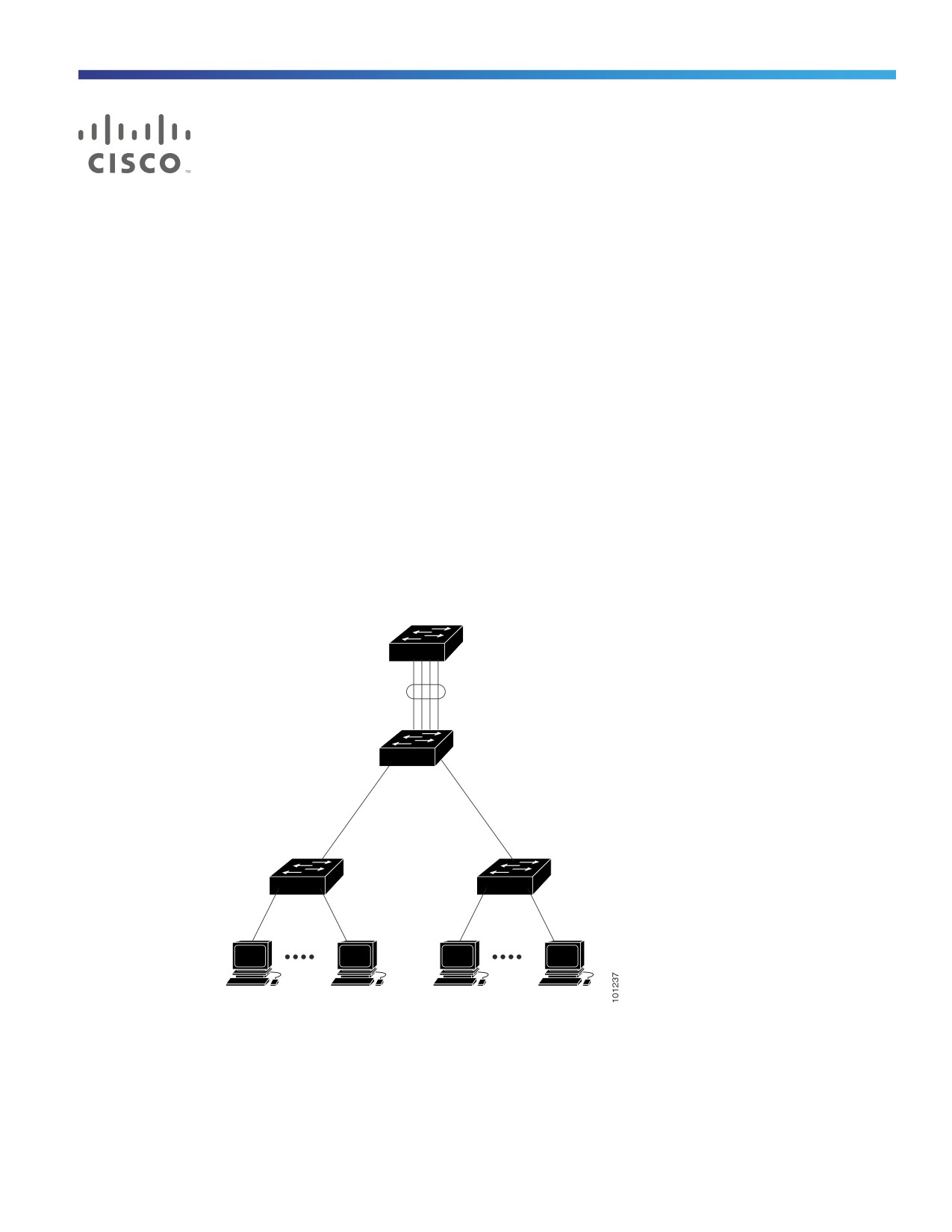
An EtherChannel consists of individual Ethernet links bundled into a single logical link as shown in Figure 110 on
page 1069.
Figure 110 Typical EtherChannel Configuration
Catalyst 8500
series switch
Gigabit EtherChannel
1000BASE-X
1000BASE-X
10/100
10/100
Switched
Switched
links
links
Workstations
Workstations
The EtherChannel provides full-duplex bandwidth up 2 Gb/s (Gigabit EtherChannel) between your switch and another
switch or host. Each EtherChannel can consist of up to eight compatibly configured Ethernet ports.
The number of EtherChannels is limited to 10. For more information, see EtherChannel Configuration Guidelines,
page 1077.
1069
Configuring EtherChannels
Information About Configuring EtherChannels
You can configure an EtherChannel in one of these modes: Port Aggregation Protocol (PAgP), Link Aggregation Control
Protocol (LACP), or On. Configure both ends of the EtherChannel in the same mode:
When you configure one end of an EtherChannel in either PAgP or LACP mode, the system negotiates with the other
end of the channel to determine which ports should become active. Incompatible ports are put into an independent
state and continue to carry data traffic as would any other single link. The port configuration does not change, but
the port does not participate in the EtherChannel.
When you configure an EtherChannel in the on mode, no negotiations take place. The switch forces all compatible
ports to become active in the EtherChannel. The other end of the channel (on the other switch) must also be
configured in the on mode; otherwise, packet loss can occur.
If a link within an EtherChannel fails, traffic previously carried over that failed link moves to the remaining links within the
EtherChannel. If traps are enabled on the switch, a trap is sent for a failure that identifies the switch, the EtherChannel,
and the failed link. Inbound broadcast and multicast packets on one link in an EtherChannel are blocked from returning
on any other link of the EtherChannel.
Port-Channel Interfaces
When you create an EtherChannel, a port-channel logical interface is involved:
With Layer 2 ports, use the channel-group interface configuration command to dynamically create the port-channel
logical interface.
You also can use the interface port-channel port-channel-number global configuration command to manually
create the port-channel logical interface, but then you must use the channel-group channel-group-number
command to bind the logical interface to a physical port. The channel-group-number can be the same as the
port-channel-number, or you can use a new number. If you use a new number, the channel-group command
dynamically creates a new port channel.
With Layer 3 ports, you should manually create the logical interface by using the interface port-channel global
configuration command followed by the no switchport interface configuration command. Then you manually assign
an interface to the EtherChannel by using the channel-group interface configuration command.
For both Layer 2 and Layer 3 ports, the channel-group command binds the physical port and the logical interface
together as shown in Figure 111 on page 1071.
Each EtherChannel has a port-channel logical interface numbered from 1 to 10. This port-channel interface number
corresponds to the one specified with the channel-group interface configuration command.
1070

Configuring EtherChannels
Information About Configuring EtherChannels
Figure 111 Relationship of Physical Ports, Logical Port Channels, and Channel Groups
Logical
port-channel
Channel-group
binding
Physical ports
After you configure an EtherChannel, configuration changes applied to the port-channel interface apply to all the physical
ports assigned to the port-channel interface. Configuration changes applied to the physical port affect only the port
where you apply the configuration. To change the parameters of all ports in an EtherChannel, apply configuration
commands to the port-channel interface, for example, spanning-tree commands or commands to configure a Layer 2
EtherChannel as a trunk.
Port Aggregation Protocol
The Port Aggregation Protocol (PAgP) is a Cisco-proprietary protocol that can be run only on Cisco switches and on
those switches licensed by vendors to support PAgP. PAgP facilitates the automatic creation of EtherChannels by
exchanging PAgP packets between Ethernet ports.
By using PAgP, the switch learns the identity of partners capable of supporting PAgP and the capabilities of each port. It
then dynamically groups similarly configured ports into a single logical link (channel or aggregate port). Similarly
configured ports are grouped based on hardware, administrative, and port parameter constraints. For example, PAgP
groups the ports with the same speed, duplex mode, native VLAN, VLAN range, and trunking status and type. After
grouping the links into an EtherChannel, PAgP adds the group to the spanning tree as a single switch port.
PAgP Modes
Table 70User-Configurable EtherChannel PAgP Modes, page 1072 shows the user-configurable EtherChannel PAgP
modes for the channel-group interface configuration command.
1071

Configuring EtherChannels
Information About Configuring EtherChannels
Table 70
User-Configurable EtherChannel PAgP Modes
Mode
Description
auto
Places a port into a passive negotiating state, in which the port responds to PAgP packets it receives but
does not start PAgP packet negotiation. This setting minimizes the transmission of PAgP packets.
desirable
Places a port into an active negotiating state, in which the port starts negotiations with other ports by
sending PAgP packets.
Switch ports exchange PAgP packets only with partner ports configured in the auto or desirable modes. Ports
configured in the on mode do not exchange PAgP packets.
Both the auto and desirable modes enable ports to negotiate with partner ports to form an EtherChannel based on
criteria such as port speed and, for Layer 2 EtherChannels, trunking state and VLAN numbers.
Ports can form an EtherChannel when they are in different PAgP modes as long as the modes are compatible. For
example:
A port in the desirable mode can form an EtherChannel with another port that is in the desirable or auto mode.
A port in the auto mode can form an EtherChannel with another port in the desirable mode.
A port in the auto mode cannot form an EtherChannel with another port that is also in the auto mode because neither
port starts PAgP negotiation.
If your switch is connected to a partner that is PAgP-capable, you can configure the switch port for nonsilent operation
by using the non-silent keyword. If you do not Specifies non-silent with the auto or desirable mode, silent mode is
assumed.
Use the silent mode when the switch is connected to a device that is not PAgP-capable and seldom, if ever, sends
packets. An example of a silent partner is a file server or a packet analyzer that is not generating traffic. In this case,
running PAgP on a physical port connected to a silent partner prevents that switch port from ever becoming operational.
However, the silent setting allows PAgP to operate, to attach the port to a channel group, and to use the port for
transmission.
PAgP Learn Method and Priority
Network devices are classified as PAgP physical learners or aggregate-port learners. A device is a physical learner if it
learns addresses by physical ports and directs transmissions based on that knowledge. A device is an aggregate-port
learner if it learns addresses by aggregate (logical) ports. The learn method must be configured the same at both ends
of the link.
When a device and its partner are both aggregate-port learners, they learn the address on the logical port-channel. The
device sends packets to the source by using any of the ports in the EtherChannel. With aggregate-port learning, it is not
important on which physical port the packet arrives.
PAgP cannot automatically detect when the partner device is a physical learner and when the local device is an
aggregate-port learner. Therefore, you must manually set the learning method on the local device to learn addresses by
physical ports. You also must set the load-distribution method to source-based distribution, so that any given source
MAC address is always sent on the same physical port.
You also can configure a single port within the group for all transmissions and use other ports for hot standby. The unused
ports in the group can be swapped into operation in just a few seconds if the selected single port loses hardware-signal
detection. You can configure which port is always selected for packet transmission by changing its priority with the pagp
port-priority interface configuration command. The higher the priority, the more likely that the port will be selected.
Note: The switch supports address learning only on aggregate ports even though the physical-port keyword is provided
in the CLI. The pagp learn-method command and the pagp port-priority command have no effect on the switch
hardware, but they are required for PAgP interoperability with devices that only support address learning by physical
1072
Configuring EtherChannels
Information About Configuring EtherChannels
ports.
When the link partner of the switch is a physical learner (such as a Catalyst 1900 series switch), we recommend that you
configure the switch as a physical-port learner by using the pagp learn-method physical-port interface configuration
command. Set the load-distribution method based on the source MAC address by using the port-channel load-balance
src-mac global configuration command. The switch then sends packets to the Catalyst 1900 switch using the same port
in the EtherChannel from which it learned the source address. Only use the pagp learn-method command in this
situation.
PAgP Interaction with Virtual Switches and Dual-Active Detection
A virtual switch can be two or more core switches connected by virtual switch links (VSLs) that carry control and data
traffic between them. One of the switches is in active mode. The others are in standby mode. For redundancy, remote
switches, are connected to the virtual switch by remote satellite links (RSLs).
If the VSL between two switches fails, one switch does not know the status of the other. Both switches could change to
the active mode, causing a dual-active situation in the network with duplicate configurations (including duplicate IP
addresses and bridge identifiers). The network might go down.
To prevent a dual-active situation, the core switches send PAgP protocol data units (PDUs) through the RSLs to the
remote switches. The PAgP PDUs identify the active switch, and the remote switches forward the PDUs to core switches
so that the core switches are in sync. If the active switch fails or resets, the standby switch takes over as the active switch.
If the VSL goes down, one core switch knows the status of the other and does not change state.
PAgP Interaction with Other Features
The Dynamic Trunking Protocol (DTP) and the Cisco Discovery Protocol (CDP) send and receive packets over the physical
ports in the EtherChannel. Trunk ports send and receive PAgP protocol data units (PDUs) on the lowest numbered VLAN.
In Layer 2 EtherChannels, the first port in the channel that comes up provides its MAC address to the EtherChannel. If
this port is removed from the bundle, one of the remaining ports in the bundle provides its MAC address to the
EtherChannel.
PAgP sends and receives PAgP PDUs only from ports that are up and have PAgP enabled for the auto or desirable mode.
Link Aggregation Control Protocol
The LACP is defined in IEEE 802.3ad and enables Cisco switches to manage Ethernet channels between switches that
conform to the IEEE 802.3ad protocol. LACP facilitates the automatic creation of EtherChannels by exchanging LACP
packets between Ethernet ports.
By using LACP, the switch learns the identity of partners capable of supporting LACP and the capabilities of each port.
It then dynamically groups similarly configured ports into a single logical link (channel or aggregate port). Similarly
configured ports are grouped based on hardware, administrative, and port parameter constraints. For example, LACP
groups the ports with the same speed, duplex mode, native VLAN, VLAN range, and trunking status and type. After
grouping the links into an EtherChannel, LACP adds the group to the spanning tree as a single switch port.
LACP Modes
Table 2 shows the user-configurable EtherChannel LACP modes for the channel-group interface configuration
command.
1073
Configuring EtherChannels
Information About Configuring EtherChannels
Table 71
User-Configurable EtherChannel LACP Modes
Mode
Description
active
Places a port into an active negotiating state in which the port starts negotiations with other ports by
sending LACP packets.
passive
Places a port into a passive negotiating state in which the port responds to LACP packets that it receives,
but does not start LACP packet negotiation. This setting minimizes the transmission of LACP packets.
Both the active and passive LACP modes enable ports to negotiate with partner ports to an EtherChannel based on
criteria such as port speed and, for Layer 2 EtherChannels, trunking state and VLAN numbers.
Ports can form an EtherChannel when they are in different LACP modes as long as the modes are compatible. For
example:
A port in the active mode can form an EtherChannel with another port that is in the active or passive mode.
A port in the passive mode cannot form an EtherChannel with another port that is also in the passive mode because
neither port starts LACP negotiation.
LACP Hot-Standby Ports
When enabled, LACP tries to configure the maximum number of LACP-compatible ports in a channel, up to a maximum
of 16 ports. Only eight LACP links can be active at one time. The software places any additional links in a hot-standby
mode. If one of the active links becomes inactive, a link that is in the hot-standby mode becomes active in its place.
If you configure more than eight links for an EtherChannel group, the software automatically decides which of the
hot-standby ports to make active based on the LACP priority. To every link between systems that operate LACP, the
software assigns a unique priority made up of these elements (in priority order):
LACP system priority
System ID (the switch MAC address)
LACP port priority
Port number
In priority comparisons, numerically lower values have higher priority. The priority decides which ports should be put in
standby mode when there is a hardware limitation that prevents all compatible ports from aggregating.
Determining which ports are active and which are hot standby is a two-step procedure. First the system with a
numerically lower system priority and system-id is placed in charge of the decision. Next, that system decides which
ports are active and which are hot standby, based on its values for port priority and port number. The port-priority and
port-number values for the other system are not used.
You can change the default values of the LACP system priority and the LACP port priority to affect how the software
selects active and standby links.
By default, all ports use the same port priority. If the local system has a lower value for the system priority and the system
ID than the remote system, you can affect which of the hot-standby links become active first by changing the port priority
of LACP EtherChannel ports to a lower value than the default. The hot-standby ports that have lower port numbers
become active in the channel first. You can use the show etherchannel summary privileged EXEC command to see
which ports are in the hot-standby mode (denoted with an H port-state flag).
If LACP is not able to aggregate all the ports that are compatible (for example, the remote system might have more
restrictive hardware limitations), all the ports that cannot be actively included in the EtherChannel are put in the
hot-standby state and are used only if one of the channeled ports fails.
1074
Configuring EtherChannels
Information About Configuring EtherChannels
LACP Interaction with Other Features
The DTP and the CDP send and receive packets over the physical ports in the EtherChannel. Trunk ports send and receive
LACP PDUs on the lowest numbered VLAN.
In Layer 2 EtherChannels, the first port in the channel that comes up provides its MAC address to the EtherChannel. If
this port is removed from the bundle, one of the remaining ports in the bundle provides its MAC address to the
EtherChannel.
LACP sends and receives LACP PDUs only from ports that are up and have LACP enabled for the active or passive mode.
EtherChannel On Mode
EtherChannel on mode can be used to manually configure an EtherChannel. The on mode forces a port to join an
EtherChannel without negotiations. The on mode can be useful if the remote device does not support PAgP or LACP. In
the on mode, a usable EtherChannel exists only when the switches at both ends of the link are configured in the on mode.
Ports that are configured in the on mode in the same channel group must have compatible port characteristics, such as
speed and duplex. Ports that are not compatible are suspended, even though they are configured in the on mode.
Caution: You should use care when using the on mode. This is a manual configuration, and ports on both ends of the
EtherChannel must have the same configuration. If the group is misconfigured, packet loss or spanning-tree loops
can occur.
Load Balancing and Forwarding Methods
EtherChannel balances the traffic load across the links in a channel by reducing part of the binary pattern formed from
the addresses in the frame to a numerical value that selects one of the links in the channel. EtherChannel load balancing
can use MAC addresses or IP addresses, source or destination addresses, or both source and destination addresses.
The selected mode applies to all EtherChannels configured on the switch. You configure the load balancing and
forwarding method by using the port-channel load-balance global configuration command.
With source-MAC address forwarding, when packets are forwarded to an EtherChannel, they are distributed across the
ports in the channel based on the source-MAC address of the incoming packet. Therefore, to provide load balancing,
packets from different hosts use different ports in the channel, but packets from the same host use the same port in the
channel.
With destination-MAC address forwarding, when packets are forwarded to an EtherChannel, they are distributed across
the ports in the channel based on the destination host’s MAC address of the incoming packet. Therefore, packets to the
same destination are forwarded over the same port, and packets to a different destination are sent on a different port in
the channel.
With source-and-destination MAC address forwarding, when packets are forwarded to an EtherChannel, they are
distributed across the ports in the channel based on both the source and destination MAC addresses. This forwarding
method, a combination source-MAC and destination-MAC address forwarding methods of load distribution, can be used
if it is not clear whether source-MAC or destination-MAC address forwarding is better suited on a particular switch. With
source-and-destination MAC-address forwarding, packets sent from host A to host B, host A to host C, and host C to
host B could all use different ports in the channel.
With source-IP address-based forwarding, when packets are forwarded to an EtherChannel, they are distributed across
the ports in the EtherChannel based on the source-IP address of the incoming packet. Therefore, to provide
load-balancing, packets from different IP addresses use different ports in the channel, but packets from the same IP
address use the same port in the channel.
1075
Configuring EtherChannels
Information About Configuring EtherChannels
With destination-IP address-based forwarding, when packets are forwarded to an EtherChannel, they are distributed
across the ports in the EtherChannel based on the destination-IP address of the incoming packet. Therefore, to provide
load-balancing, packets from the same IP source address sent to different IP destination addresses could be sent on
different ports in the channel. But packets sent from different source IP addresses to the same destination IP address
are always sent on the same port in the channel.
With source-and-destination IP address-based forwarding, packets are sent to an EtherChannel and distributed across
the EtherChannel ports, based on both the source and destination IP addresses of the incoming packet. This forwarding
method, a combination of source-IP and destination-IP address-based forwarding, can be used if it is not clear whether
source-IP or destination-IP address-based forwarding is better suited on a particular switch. In this method, packets
sent from the IP address A to IP address B, from IP address A to IP address C, and from IP address C to IP address B
could all use different ports in the channel.
Different load-balancing methods have different advantages, and the choice of a particular load-balancing method
should be based on the position of the switch in the network and the kind of traffic that needs to be load-distributed. In
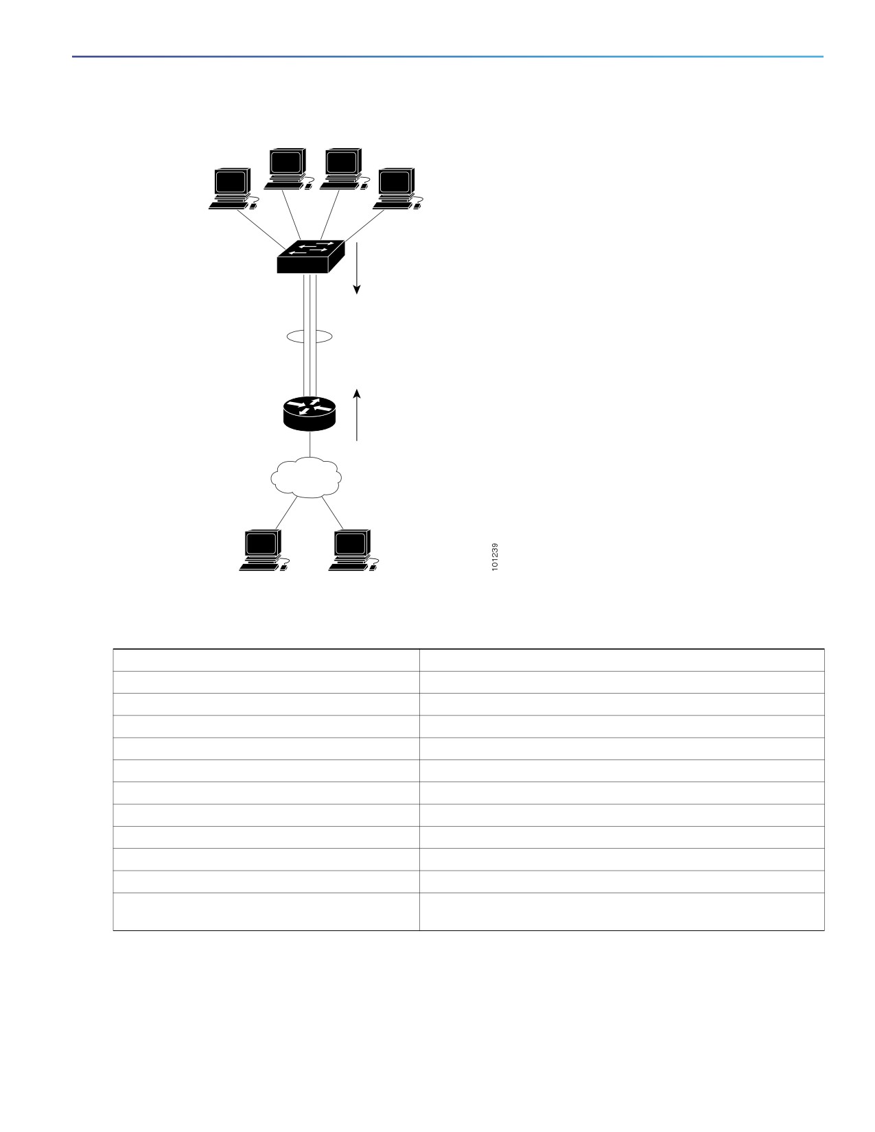
Figure 112 on page 1077, an EtherChannel from a switch that is aggregating data from four workstations communicates
with a router. Because the router is a single-MAC-address device, source-based forwarding on the switch EtherChannel
ensures that the switch uses all available bandwidth to the router. The router is configured for destination-based
forwarding because the large number of workstations ensures that the traffic is evenly distributed from the router
EtherChannel.
Use the option that provides the greatest variety in your configuration. For example, if the traffic on a channel is only
going to a single MAC address, using the destination-MAC address always chooses the same link in the channel. Using
source addresses or IP addresses might result in better load balancing.
1076
Configuring EtherChannels
Information About Configuring EtherChannels
Figure 112 Load Distribution and Forwarding Methods
Switch with
source-based
forwarding enabled
EtherChannel
Cisco router
with destination-based
forwarding enabled
Default EtherChannel Settings
Feature
Default Setting
Channel groups
None assigned.
Port-channel logical interface
None defined.
PAgP mode
No default.
PAgP learn method
Aggregate-port learning on all ports.
PAgP priority
128 on all ports.
LACP mode
No default.
LACP learn method
Aggregate-port learning on all ports.
LACP port priority
32768 on all ports.
LACP system priority
32768.
LACP system ID
LACP system priority and the switch MAC address.
Load balancing
Load distribution on the switch is based on the source-MAC
address of the incoming packet.
EtherChannel Configuration Guidelines
If improperly configured, some EtherChannel ports are automatically disabled to avoid network loops and other problems.
Follow these guidelines to avoid configuration problems:
1077
Configuring EtherChannels
Information About Configuring EtherChannels
Do not try to configure more than 6 EtherChannels on the switch.
Configure a PAgP EtherChannel with up to ten Ethernet ports of the same type.
Configure a LACP EtherChannel with up to16 Ethernet ports of the same type. Up to eight ports can be active, and
up to eight ports can be in standby mode.
Configure all ports in an EtherChannel to operate at the same speeds and duplex modes.
Enable all ports in an EtherChannel. A port in an EtherChannel that is disabled by using the shutdown interface
configuration command is treated as a link failure, and its traffic is transferred to one of the remaining ports in the
EtherChannel.
When a group is first created, all ports follow the parameters set for the first port to be added to the group. If you
change the configuration of one of these parameters, you must also make the changes to all ports in the group:
— Allowed-VLAN list
— Spanning-tree path cost for each VLAN
— Spanning-tree port priority for each VLAN
— Spanning-tree Port Fast setting
Do not configure a port to be a member of more than one EtherChannel group.
Do not configure an EtherChannel in both the PAgP and LACP modes. EtherChannel groups running PAgP and LACP
can coexist on the same switch. Individual EtherChannel groups can run either PAgP or LACP, but they cannot
interoperate.
Do not configure a Switched Port Analyzer (SPAN) destination port as part of an EtherChannel.
Do not configure a secure port as part of an EtherChannel or the reverse.
Do not configure a private-VLAN port as part of an EtherChannel.
Do not configure a port that is an active or a not-yet-active member of an EtherChannel as an IEEE 802.1x port. If
you try to enable IEEE 802.1x on an EtherChannel port, an error message appears, and IEEE 802.1x is not enabled.
If EtherChannels are configured on switch interfaces, remove the EtherChannel configuration from the interfaces
before globally enabling IEEE 802.1x on a switch by using the dot1x system-auth-control global configuration
command.
For Layer 2 EtherChannels:
— Assign all ports in the EtherChannel to the same VLAN, or configure them as trunks. Ports with different native
VLANs cannot form an EtherChannel.
— If you configure an EtherChannel from trunk ports, verify that the trunking mode (ISL or IEEE 802.1Q) is the same
on all the trunks. Inconsistent trunk modes on EtherChannel ports can have unexpected results.
— An EtherChannel supports the same allowed range of VLANs on all the ports in a trunking Layer 2 EtherChannel.
If the allowed range of VLANs is not the same, the ports do not form an EtherChannel even when PAgP is set to
the auto or desirable mode.
— Ports with different spanning-tree path costs can form an EtherChannel if they are otherwise compatibly
configured. Setting different spanning-tree path costs does not, by itself, make ports incompatible for the
formation of an EtherChannel.
1078
Configuring EtherChannels
How to Configure EtherChannels
How to Configure EtherChannels
Note: After you configure an EtherChannel, configuration changes applied to the port-channel interface apply to all the
physical ports assigned to the port-channel interface, and configuration changes applied to the physical port affect only
the port where you apply the configuration.
Configuring Layer 2 EtherChannels
You configure Layer 2 EtherChannels by assigning ports to a channel group with the channel-group interface
configuration command. This command automatically creates the port-channel logical interface.
This required task explains how to configure a Layer 2 Ethernet port to a Layer 2 EtherChannel.
Command
Purpose
1.
configure terminal
Enters global configuration mode.
2.
interface interface-id
Specifies a physical port, and enter interface configuration
mode.
Valid interfaces include physical ports.
For a PAgP EtherChannel, you can configure up to eight ports of
the same type and speed for the same group.
For a LACP EtherChannel, you can configure up to 16 Ethernet
ports of the same type. Up to eight ports can be active, and up
to eight ports can be in standby mode.
1079

Configuring EtherChannels
How to Configure EtherChannels
Command
Purpose
3.
switchport mode {access | trunk}
Assigns all ports as static-access ports in the same VLAN, or
configures them as trunks.
switchport access vlan vlan-id
If you configure the port as a static-access port, assign it to only
one VLAN. The range is 1 to 4096.
4.
channel-group channel-group-number mode
Assigns the port to a channel group, and specifies the PAgP or
{auto [non-silent] | desirable [non-silent] | on}
the LACP mode.
| {active | passive}
For channel-group-number, the range is 1 to 10.
For mode, select one of these keywords:
auto—Enables PAgP only if a PAgP device is detected. It
places the port into a passive negotiating state, in which the
port responds to PAgP packets it receives but does not start
PAgP packet negotiation.
desirable—Unconditionally enables PAgP. It places the port
into an active negotiating state, in which the port starts
negotiations with other ports by sending PAgP packets.
on—Forces the port to channel without PAgP or LACP. In the
on mode, an EtherChannel exists only when a port group in
the on mode is connected to another port group in the on
mode.
non-silent—(Optional) If your switch is connected to a
partner that is PAgP-capable, configure the switch port for
nonsilent operation when the port is in the auto or desirable
mode. If you do not Specifies non-silent, silent is assumed.
The silent setting is for connections to file servers or packet
analyzers. This setting allows PAgP to operate, to attach the
port to a channel group, and to use the port for transmission.
active—Enables LACP only if a LACP device is detected. It
places the port into an active negotiating state in which the
port starts negotiations with other ports by sending LACP
packets.
passive—Enables LACP on the port and places it into a
passive negotiating state in which the port responds to
LACP packets that it receives, but does not start LACP
packet negotiation.
For information on compatible modes for the switch and its
partner, see PAgP Modes, page 1071 and the LACP Modes,
page 1073.
5.
end
Returns to privileged EXEC mode.
Configuring EtherChannel Load Balancing
This task is optional.
1080

Configuring EtherChannels
How to Configure EtherChannels
Command
Purpose
1.
configure terminal
Enters global configuration mode.
2.
port-channel load-balance {dst-ip | dst-mac |
Configures an EtherChannel load-balancing method.
src-dst-ip | src-dst-mac | src-ip | src-mac}
The default is src-mac.
Select one of these load-distribution methods:
dst-ip—Specifies the destination-host IP address.
dst-mac—Specifies the destination-host MAC address of
the incoming packet.
src-dst-ip— Specifies the source-and-destination host-IP
address.
src-dst-mac—Specifies the source-and-destination
host-MAC address.
src-ip— Specifies the source-host IP address.
src-mac—Specifies the source-MAC address of the
incoming packet.
3.
end
Returns to privileged EXEC mode.
Configuring the PAgP Learn Method and Priority
This task is optional.
Command
Purpose
1.
configure terminal
Enters global configuration mode.
2.
interface interface-id
Specifies the port for transmission, and enter interface
configuration mode.
1081

Configuring EtherChannels
How to Configure EtherChannels
Command
Purpose
3.
pagp learn-method physical-port
Selects the PAgP learning method.
By default, aggregation-port learning is selected, which means
the switch sends packets to the source by using any of the ports
in the EtherChannel. With aggregate-port learning, it is not
important on which physical port the packet arrives.
Select physical-port to connect with another switch that is a
physical learner. Make sure to configure the port-channel
load-balance global configuration command to src-mac as
described in the Configuring EtherChannel Load Balancing,
page 1080.
The learning method must be configured the same at both ends
of the link.
4.
pagp port-priority priority
Assigns a priority so that the selected port is chosen for packet
transmission.
For priority, the range is 0 to 255. The default is 128. The higher
the priority, the more likely that the port will be used for PAgP
transmission.
5.
end
Returns to privileged EXEC mode.
Configuring the LACP Hot-Standby Ports
This task is optional.
Command
Purpose
1.
configure terminal
Enters global configuration mode.
2.
lacp system-priority priority
Configures the LACP system priority.
For priority, the range is 1 to 65535. The default is 32768.
The lower the value, the higher the system priority.
3.
interface interface-id
Specifies the port to be configured, and enters interface
configuration mode.
4.
lacp port-priority priority
Configures the LACP port priority.
For priority, the range is 1 to 65535. The default is 32768. The
lower the value, the more likely that the port will be used for
LACP transmission.
5.
end
Returns to privileged EXEC mode.
1082

Configuring EtherChannels
Monitoring and Maintaining EtherChannels
Monitoring and Maintaining EtherChannels
Command
Purpose
show etherchannel [channel-group-number
Displays EtherChannel information in a brief,
{detail | port | port-channel | protocol |
detailed, and one-line summary form. Also
summary}] {detail | load-balance | port |
displays the load-balance or frame-distribution
port-channel | protocol | summary}
scheme, port, port-channel, and protocol
information.
show pagp [channel-group-number] {counters |
Displays PAgP information such as traffic
internal | neighbor}
information, the internal PAgP configuration, and
neighbor information.
show pagp [channel-group-number]
Displays the dual-active detection status.
dual-active
show lacp [channel-group-number] {counters |
Displays LACP information such as traffic
internal | neighbor}
information, the internal LACP configuration, and
neighbor information.
Configuration Examples for Configuring EtherChannels
Configuring EtherChannels: Examples
This example shows how to configure an EtherChannel and assign two ports as static-access ports in VLAN 10 to
channel 5 with the PAgP mode desirable:
Switch# configure terminal
Switch(config)# interface range GigabitEthernet1/17 -2
Switch(config-if-range)# switchport mode access
Switch(config-if-range)# switchport access vlan 10
Switch(config-if-range)# channel-group 5 mode desirable non-silent
Switch(config-if-range)# end
This example shows how to configure an EtherChannel and assign two ports as static-access ports in VLAN 10 to
channel 5 with the LACP mode active:
Switch# configure terminal
Switch(config)# interface range GigabitEthernet1/17 -2
Switch(config-if-range)# switchport mode access
Switch(config-if-range)# switchport access vlan 10
Switch(config-if-range)# channel-group 5 mode active
Switch(config-if-range)# end
Additional References
The following sections provide references related to switch administration:
1083

Configuring EtherChannels
Additional References
Related Documents
Related Topic
Document Title
Cisco IOS basic commands
Cisco IOS Configuration Fundamentals Command Reference
Standards
Standards
Title
No new or modified standards are supported by this
—
feature, and support for existing standards has not
been modified by this feature.
MIBs
MIBs
MIBs Link
—
To locate and download MIBs using Cisco IOS XR software, use the
Cisco MIB Locator found at the following URL and choose a platform
under the Cisco Access Products menu:
RFCs
RFCs
Title
No new or modified RFCs are supported by this
—
feature, and support for existing RFCs has not been
modified by this feature.
Technical Assistance
Description
Link
The Cisco Technical Support website contains
thousands of pages of searchable technical content,
including links to products, technologies, solutions,
technical tips, and tools. Registered Cisco.com users
can log in from this page to access even more content.
1084
Troubleshooting
This chapter describes how to identify and resolve software problems related to the Cisco IOS software on the switch.
Depending on the nature of the problem, you can use the command-line interface (CLI), Network Assistant or Device
Manager to identify and solve problems.
For additional troubleshooting information, such as LED descriptions, see the Hardware Installation Guide.
Information for Troubleshooting
Autonegotiation Mismatches Prevention
The IEEE 802.3ab autonegotiation protocol manages the switch settings for speed (10 Mb/s, 100 Mb/s, and 1000 Mb/s,
excluding SFP module ports) and duplex (half or full). There are situations when this protocol can incorrectly align these
settings, reducing performance. A mismatch occurs under these circumstances:
A manually set speed or duplex parameter is different from the manually set speed or duplex parameter on the
connected port.
A port is set to autonegotiate, and the connected port is set to full duplex with no autonegotiation.
To maximize switch performance and ensure a link, follow one of these guidelines when changing the settings for duplex
and speed:
Let both ports autonegotiate both speed and duplex.
Manually set the speed and duplex parameters for the ports on both ends of the connection.
Note: If a remote device does not autonegotiate, configure the duplex settings on the two ports to match. The speed
parameter can adjust itself even if the connected port does not autonegotiate.
SFP Module Security and Identification
Cisco small form-factor pluggable (SFP) modules have a serial EEPROM that contains the module serial number, the
vendor name and ID, a unique security code, and cyclic redundancy check (CRC). When an SFP module is inserted in
the switch, the switch software reads the EEPROM to verify the serial number, vendor name and vendor ID, and
recompute the security code and CRC. If the serial number, the vendor name or vendor ID, the security code, or CRC is
invalid, the software generates a security error message and places the interface in an error-disabled state.
Note: The security error message references the GBIC_SECURITY facility. The switch supports SFP modules and does
not support GBIC modules. Although the error message text refers to GBIC interfaces and modules, the security
messages actually refer to the SFP modules and module interfaces.
If you are using a non-Cisco SFP module, remove the SFP module from the switch, and replace it with a Cisco module.
After inserting a Cisco SFP module, use the errdisable recovery cause gbic-invalid global configuration command to
verify the port status, and enter a time interval for recovering from the error-disabled state. After the elapsed interval,
the switch brings the interface out of the error-disabled state and retries the operation.
1085
Troubleshooting
Information for Troubleshooting
If the module is identified as a Cisco SFP module, but the system is unable to read vendor-data information to verify its
accuracy, an SFP module error message is generated. In this case, you should remove and reinsert the SFP module. If it
continues to fail, the SFP module might be defective.
Ping
The switch supports IP ping, which you can use to test connectivity to remote hosts. Ping sends an echo request packet
to an address and waits for a reply. Ping returns one of these responses:
Normal response—The normal response (hostname is alive) occurs in 1 to 10 seconds, depending on network traffic.
Destination does not respond—If the host does not respond, a no-answer message is returned.
Unknown host—If the host does not exist, an unknown host message is returned.
Destination unreachable—If the default gateway cannot reach the specified network, a destination-unreachable
message is returned.
Network or host unreachable—If there is no entry in the route table for the host or network, a network or host
unreachable message is returned.
Layer 2 Traceroute
The Layer 2 traceroute feature allows the switch to identify the physical path that a packet takes from a source device to
a destination device. Layer 2 traceroute supports only unicast source and destination MAC addresses. It finds the path
by using the MAC address tables of the switches in the path. When the switch detects a device in the path that does not
support Layer 2 traceroute, the switch continues to send Layer 2 trace queries and lets them time out.
The switch can only identify the path from the source device to the destination device. It cannot identify the path that a
packet takes from source host to the source device or from the destination device to the destination host.
Layer 2 Traceroute Usage Guidelines
Cisco Discovery Protocol (CDP) must be enabled on all the devices in the network. For Layer 2 traceroute to function
properly, do not disable CDP.
If any devices in the physical path are transparent to CDP, the switch cannot identify the path through these devices.
For more information about enabling CDP, see Configuring CDP, page 529
A switch is reachable from another switch when you can test connectivity by using the ping privileged EXEC
command. All switches in the physical path must be reachable from each other.
The maximum number of hops identified in the path is ten.
You can enter the traceroute mac or the traceroute mac ip privileged EXEC command on a switch that is not in the
physical path from the source device to the destination device. All switches in the path must be reachable from this
switch.
The traceroute mac command output shows the Layer 2 path only when the specified source and destination MAC
addresses belong to the same VLAN. If you specify source and destination MAC addresses that belong to different
VLANs, the Layer 2 path is not identified, and an error message appears.
If you specify a multicast source or destination MAC address, the path is not identified, and an error message
appears.
If the source or destination MAC address belongs to multiple VLANs, you must specify the VLAN to which both the
source and destination MAC addresses belong. If the VLAN is not specified, the path is not identified, and an error
message appears.
1086