Cisco Industrial Ethernet 4000, 4010 and 5000 Switch Software. Configuration Guide (2022) - page 36
Configuring IPv6 Unicast Routing
Configuration Example
RIP process "fer", port 521, multicast-group FF02::9, pid 190
Administrative distance is 120. Maximum paths is 16
Updates every 30 seconds, expire after 180
Holddown lasts 0 seconds, garbage collect after 120
Split horizon is on; poison reverse is off
Default routes are not generated
Periodic updates 9040, trigger updates 60
Interfaces:
Vlan6
GigabitEthernet0/4
GigabitEthernet0/11
GigabitEthernet0/12
Redistribution:
None
This is an example of the output from the show ipv6 neighbor privileged EXEC command:
Switch# show ipv6 neighbors
IPv6 Address
Age Link-layer Addr State Interface
3FFE:C000:0:7::777
- 0007.0007.0007 REACH Vl7
3FFE:C101:113:1::33
- 0000.0000.0033 REACH Gi0/13
This is an example of the output from the show ipv6 static privileged EXEC command:
Switch# show ipv6 static
IPv6 Static routes
Code: * - installed in RIB
* ::/0 via nexthop 3FFE:C000:0:7::777, distance 1
This is an example of the output from the show ipv6 route privileged EXEC command:
Switch# show ipv6 route
IPv6 Routing Table - 21 entries
Codes: C - Connected, L - Local, S - Static, R - RIP, B - BGP
U - Per-user Static route
I1 - ISIS L1, I2 - ISIS L2, IA - ISIS interarea, IS - ISIS summary
O - OSPF intra, OI - OSPF inter, OE1 - OSPF ext 1, OE2 - OSPF ext 2
ON1 - OSPF NSSA ext 1, ON2 - OSPF NSSA ext 2
S
::/0 [1/0]
via 3FFE:C000:0:7::777
C
3FFE:C000:0:1::/64 [0/0]
via ::, Vlan1
L
3FFE:C000:0:1:20B:46FF:FE2F:D940/128 [0/0]
via ::, Vlan1
C
3FFE:C000:0:7::/64 [0/0]
via ::, Vlan7
L
3FFE:C000:0:7:20B:46FF:FE2F:D97F/128 [0/0]
via ::, Vlan7
C
3FFE:C000:111:1::/64 [0/0]
via ::, GigabitEthernet0/11
L
3FFE:C000:111:1:20B:46FF:FE2F:D945/128 [0/0]
C
3FFE:C000:168:1::/64 [0/0]
via ::, GigabitEthernet0/4
L
3FFE:C000:168:1:20B:46FF:FE2F:D94B/128 [0/0]
via ::, GigabitEthernet0/4
C
3FFE:C000:16A:1::/64 [0/0]
via ::, Loopback10
L
3FFE:C000:16A:1:20B:46FF:FE2F:D900/128 [0/0]
via ::, Loopback10
<output truncated>
This is an example of the output from the show ipv6 traffic privileged EXEC command.
997
Configuring IPv6 Unicast Routing
Related Documents
Switch# show ipv6 traffic
IPv6 statistics:
Rcvd:
1 total, 1 local destination
0 source-routed, 0 truncated
0 format errors, 0 hop count exceeded
0 bad header, 0 unknown option, 0 bad source
0 unknown protocol, 0 not a router
0 fragments, 0 total reassembled
0 reassembly timeouts, 0 reassembly failures
Sent:
36861 generated, 0 forwarded
0 fragmented into 0 fragments, 0 failed
0 encapsulation failed, 0 no route, 0 too big
0 RPF drops, 0 RPF suppressed drops
Mcast: 1 received, 36861 sent
ICMP statistics:
Rcvd: 1 input, 0 checksum errors, 0 too short
0 unknown info type, 0 unknown error type
unreach: 0 routing, 0 admin, 0 neighbor, 0 address, 0 port
parameter: 0 error, 0 header, 0 option
0 hopcount expired, 0 reassembly timeout,0 too big
0 echo request, 0 echo reply
0 group query, 0 group report, 0 group reduce
1 router solicit, 0 router advert, 0 redirects
0 neighbor solicit, 0 neighbor advert
Sent: 10112 output, 0 rate-limited
unreach: 0 routing, 0 admin, 0 neighbor, 0 address, 0 port
parameter: 0 error, 0 header, 0 option
0 hopcount expired, 0 reassembly timeout,0 too big
0 echo request, 0 echo reply
0 group query, 0 group report, 0 group reduce
0 router solicit, 9944 router advert, 0 redirects
84 neighbor solicit, 84 neighbor advert
UDP statistics:
Rcvd: 0 input, 0 checksum errors, 0 length errors
0 no port, 0 dropped
Sent: 26749 output
TCP statistics:
Rcvd: 0 input, 0 checksum errors
Sent: 0 output, 0 retransmitted
Related Documents
For information about how Cisco Systems implements IPv6:
For information about IPv6 and other features in this chapter:
IPv6 Configuration Library, Cisco IOS Release 15M&T
IPv6 Implementation Guide, Cisco IOS Release 15.2M&T
998
Unicast Overview
This document describes how to configure unicast routing on the Cisco Industrial Ethernet Switches, hereafter referred
to as switch. To use unicast routing, the switch must be running the IP services image.
This chapter provides an overview of the following unicast routing features:
IPv4 Unicast Routing, page 999
IPv6 Unicast Routing, page 999
Enhanced Object Tracking, page 1000
IPv4 Unicast Routing
Routers and Layer 3 switches can route packets in the following ways:
By using default routing—sending traffic with a destination unknown to the router to a default outlet or destination.
By using preprogrammed static routes for the traffic
Static unicast routing forwards packets from predetermined ports through a single path into and out of a network.
Static routing does not automatically respond to changes in the network and therefore, might result in unreachable
destinations.
By dynamically calculating routes by using a routing protocol
Dynamic routing protocols are used by routers to dynamically calculate the best route for forwarding traffic. Routing
protocols supported by the switch are Routing Information Protocol (RIP), Border Gateway Protocol (BGP), Open
Shortest Path First (OSPF) protocol, Enhanced IGRP (EIGRP), System-to-Intermediate System (IS-IS), and
Bidirectional Forwarding Detection (BFD).
IPv6 Unicast Routing
IPv4 users can move to IPv6 and receive services such as end-to-end security, quality of service (QoS), and globally
unique addresses. The IPv6 address space reduces the need for private addresses and Network Address Translation
(NAT) processing by border routers at network edges.
IPv6 unicast routing support on the switch includes expanded address capability, header format simplification, improved
support of extensions and options, and hardware parsing of the extension header. The switch supports hop-by-hop
extension header packets, which are routed or bridged in software.
The switch provides IPv6 routing capability over 802.1Q trunk ports for static routes, Routing Information Protocol (RIP)
for IPv6, and Open Shortest Path First (OSPF) Version 3 Protocol. It supports up to 16 equal-cost routes and can
simultaneously forward IPv4 and IPv6 frames at line rate.
999
Unicast Overview
Enhanced Object Tracking
Enhanced Object Tracking
Enhanced object tracking on the switch provides a more complete alternative to the Hot Standby Routing Protocol (HSRP)
tracking mechanism, which allows you to track the line-protocol state of an interface. If the line protocol state of an
interface goes down, the HSRP priority of the interface is reduced and another HSRP device with a higher priority
becomes active. The enhanced object tracking feature separates the tracking mechanism from HSRP and creates a
separate, standalone tracking process that can be used by processes other than HSRP. This allows tracking other objects
in addition to the interface line-protocol state.
A client process, such as HSRP or Gateway Local Balancing Protocol (GLBP), can register an interest in tracking objects
and request notification when the tracked object changes state.This feature increases the availability and speed of
recovery of a routing system and decreases outages and outage duration.
1000
Configuring Cisco IOS IP SLAs Operations
Prerequisites for Configuring Cisco IOS IP SLAs Operations
Before configuring any IP SLAs application, we recommend that you verify the operation type supported on your
software image by using the show ip sla application privileged EXEC command.
Restrictions for Configuring Cisco IOS IP SLAs Operations
The IP SLAs responder can be a Cisco IOS Layer 2, responder-configurable switch.
The switch does not support Voice over IP (VoIP) service levels using the gatekeeper registration delay operations
measurements. Before configuring any IP SLAs application, you can use the show ip sla application privileged EXEC
command to verify that the operation type is supported on your software image.
Information About Configuring Cisco IOS IP SLAs Operations
This chapter describes how to use Cisco IOS IP Service Level Agreements (SLAs) on the switch. Cisco IP SLAs is a part
of Cisco IOS software that allows Cisco customers to analyze IP service levels for IP applications and services by using
active traffic monitoring—the generation of traffic in a continuous, reliable, and predictable manner—for measuring
network performance. With Cisco IOS IP SLAs, service provider customers can measure and provide service level
agreements, and enterprise customers can verify service levels, verify outsourced service level agreements, and
understand network performance. Cisco IOS IP SLAs can perform network assessments, verify quality of service (QoS),
ease the deployment of new services, and assist with network troubleshooting.
Cisco IOS IP SLAs
Cisco IOS IP SLAs sends data across the network to measure performance between multiple network locations or across
multiple network paths. It simulates network data and IP services and collects network performance information in real
time. Cisco IOS IP SLAs generates and analyzes traffic either between Cisco IOS devices or from a Cisco IOS device to
a remote IP device such as a network application server. Measurements provided by the various Cisco IOS IP SLAs
operations can be used for troubleshooting, for problem analysis, and for designing network topologies.
Depending on the specific Cisco IOS IP SLAs operation, various network performance statistics are monitored within the
Cisco device and stored in both command-line interface (CLI) and Simple Network Management Protocol (SNMP) MIBs.
IP SLAs packets have configurable IP and application layer options such as source and destination IP address, User
Datagram Protocol (UDP)/TCP port numbers, a type of service (ToS) byte (including Differentiated Services Code Point
[DSCP] and IP Prefix bits), Virtual Private Network (VPN) routing/forwarding instance (VRF), and URL web address.
Because Cisco IP SLAs is Layer 2 transport independent, you can configure end-to-end operations over disparate
networks to best reflect the metrics that an end user is likely to experience. IP SLAs collects a unique subset of these
performance metrics:
Delay (both round-trip and one-way)
Jitter (directional)
1001
Configuring Cisco IOS IP SLAs Operations
Information About Configuring Cisco IOS IP SLAs Operations
Packet loss (directional)
Packet sequencing (packet ordering)
Path (per hop)
Connectivity (directional)
Server or website download time
Because Cisco IOS IP SLAs is SNMP-accessible, it can also be used by performance-monitoring applications like
CiscoWorks Internetwork Performance Monitor (IPM) and other third-party Cisco partner performance management
products. Using IP SLAs can provide these benefits:
Service-level agreement monitoring, measurement, and verification.
Network performance monitoring
— Measures the jitter, latency, or packet loss in the network.
— Provides continuous, reliable, and predictable measurements.
IP service network health assessment to verify that the existing QoS is sufficient for new IP services.
Edge-to-edge network availability monitoring for proactive verification and connectivity testing of network resources
(for example, shows the network availability of an NFS server used to store business critical data from a remote site).
Troubleshooting of network operation by providing consistent, reliable measurement that immediately identifies
problems and saves troubleshooting time.
Multiprotocol Label Switching (MPLS) performance monitoring and network verification (if the switch supports
MPLS)
Cisco IOS IP SLAs to Measure Network Performance
You can use IP SLAs to monitor the performance between any area in the network—core, distribution, and edge—without
deploying a physical probe. It uses generated traffic to measure network performance between two networking devices.
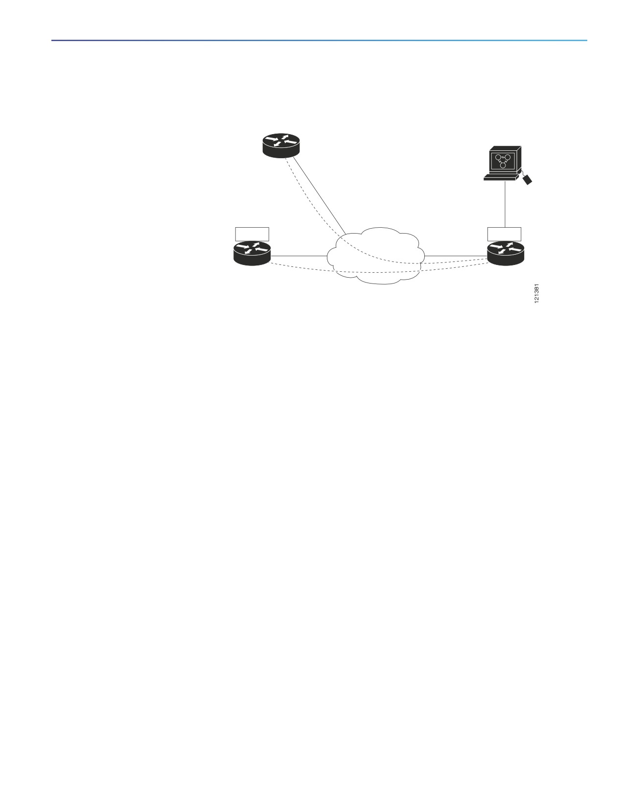
Figure 108 on page 1003 shows how IP SLAs begins when the source device sends a generated packet to the
destination device. After the destination device receives the packet, depending on the type of IP SLAs operation, it
responds with time-stamp information for the source to make the calculation on performance metrics. An IP SLAs
operation performs a network measurement from the source device to a destination in the network using a specific
protocol such as UDP.
1002
Configuring Cisco IOS IP SLAs Operations
Information About Configuring Cisco IOS IP SLAs Operations
Figure 108 Cisco IOS IP SLAs Operation
Performance
Any IP device
management
application
IP SLA measurement
and IP SLA responder to
IP SLA responder
SNMP
IP SLA
IP SLA
IP network
IP SLA responder
IP SLA source
IP SLA measurement
and IP SLA responder to
IP SLA responder
To implement IP SLAs network performance measurement, you need to perform these tasks:
— Enable the IP SLAs responder, if required.
— Configure the required IP SLAs operation type.
— Configure any options available for the specified operation type.
— Configure threshold conditions, if required.
— Schedule the operation to run, then let the operation run for a period of time to gather statistics.
— Display and interpret the results of the operation using the Cisco IOS CLI or a network management system
(NMS) system with SNMP.
IP SLAs Responder and IP SLAs Control Protocol
The IP SLAs responder is a component embedded in the destination Cisco device that allows the system to anticipate
and respond to IP SLAs request packets. The responder provides accurate measurements without the need for dedicated
probes. The responder uses the Cisco IOS IP SLAs Control Protocol to provide a mechanism through which it can be
notified on which port it should listen and respond. Only a Cisco IOS device can be a source for a destination IP SLAs
Responder.
Figure 108 on page 1003 shows where the Cisco IOS IP SLAs responder fits in the IP network. The responder listens on
a specific port for control protocol messages sent by an IP SLAs operation. Upon receipt of the control message, it
enables the specified UDP or TCP port for the specified duration. During this time, the responder accepts the requests
and responds to them. It disables the port after it responds to the IP SLAs packet, or when the specified time expires.
MD5 authentication for control messages is available for added security.
You do not need to enable the responder on the destination device for all IP SLAs operations. For example, a responder
is not required for services that are already provided by the destination router (such as Telnet or HTTP). You cannot
configure the IP SLAs responder on non-Cisco devices and Cisco IOS IP SLAs can send operational packets only to
services native to those devices.
1003
Configuring Cisco IOS IP SLAs Operations
Information About Configuring Cisco IOS IP SLAs Operations
Response Time Computation for IP SLAs
Switches and routers can take tens of milliseconds to process incoming packets due to other high priority processes.
This delay affects the response times because the test-packet reply might be in a queue while waiting to be processed.
In this situation, the response times would not accurately represent true network delays. IP SLAs minimizes these
processing delays on the source device as well as on the target device (if the responder is being used) to determine true
round-trip times. IP SLAs test packets use time stamping to minimize the processing delays.
When the IP SLAs responder is enabled, it allows the target device to take time stamps when the packet arrives on the
interface at interrupt level and again just as it is leaving, eliminating the processing time. This time stamping is made with
a granularity of sub-milliseconds (ms).
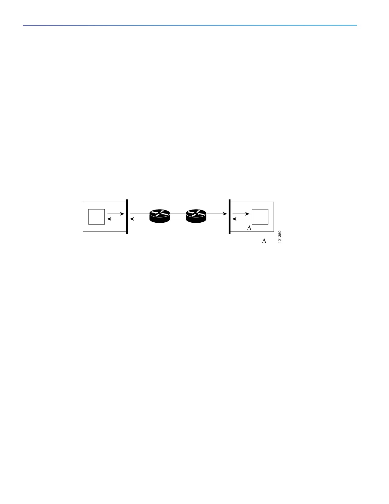
Figure 109 on page 1004 demonstrates how the responder works. Four time stamps are taken to make the calculation
for round-trip time. At the target router, with the responder functionality enabled, time stamp 2 (TS2) is subtracted from
time stamp 3 (TS3) to produce the time spent processing the test packet as represented by delta. This delta value is then
subtracted from the overall round-trip time. Notice that the same principle is applied by IP SLAs on the source router
where the incoming time stamp 4 (TS4) is also taken at the interrupt level to allow for greater accuracy.
Figure 109 Cisco IOS IP SLAs Responder Time Stamping
Source router
Target router
Responder
T2
T1
T3
T4
=T3-T2
RTT (Round-trip time) = T4 (Time stamp 4) - T1 (Time stamp 1) -
An additional benefit of the two time stamps at the target device is the ability to track one-way delay, jitter, and directional
packet loss. Because much network behavior is asynchronous, it is critical to have these statistics. However, to capture
one-way delay measurements, you must configure both the source router and target router with Network Time Protocol
(NTP) so that the source and target are synchronized to the same clock source. One-way jitter measurements do not
require clock synchronization.
IP SLAs Operation Scheduling
When you configure an IP SLAs operation, you must schedule the operation to begin capturing statistics and collecting
error information. You can schedule an operation to start immediately or to start at a certain month, day, and hour. You
can use the pending option to set the operation to start at a later time. The pending option is an internal state of the
operation that is visible through SNMP. The pending state is also used when an operation is a reaction (threshold)
operation waiting to be triggered. You can schedule a single IP SLAs operation or a group of operations at one time.
You can schedule several IP SLAs operations on a switch running the IP services image by using a single command
through the Cisco IOS CLI or the CISCO RTTMON-MIB. Scheduling the operations to run at evenly distributed times
allows you to control the amount of IP SLAs monitoring traffic. This distribution of IP SLAs operations helps minimize the
CPU utilization and thus improves network scalability.
IP SLAs Operation Threshold Monitoring
To support successful service level agreement monitoring, you must have mechanisms that notify you immediately of any
possible violation. IP SLAs can send SNMP traps that are triggered by events such as these:
Connection loss
Timeout
Round-trip time threshold
1004
Configuring Cisco IOS IP SLAs Operations
Information About Configuring Cisco IOS IP SLAs Operations
Average jitter threshold
One-way packet loss
One-way jitter
One-way mean opinion score (MOS)
One-way latency
An IP SLAs threshold violation can also trigger another IP SLAs operation for further analysis. For example, the frequency
could be increased or an ICMP path echo or ICMP path jitter operation could be initiated for troubleshooting.
Determining the type of threshold and the level to set can be complex, and depends on the type of IP service being used
in the network.
IP Service Levels by Using the UDP Jitter Operation
Jitter means interpacket delay variance. When multiple packets are sent consecutively 10 ms apart from source to
destination, if the network is behaving correctly, the destination should receive them 10 ms apart. But if there are delays
in the network (like queuing, arriving through alternate routes, and so on) the arrival delay between packets might be
more than or less than 10 ms with a positive jitter value meaning that the packets arrived more than 10 ms apart. If the
packets arrive 12 ms apart, positive jitter is 2 ms; if the packets arrive 8 ms apart, negative jitter is 2 ms. For
delay-sensitive networks, positive jitter values are undesirable, and a jitter value of 0 is ideal.
In addition to monitoring jitter, the IP SLAs UDP jitter operation can be used as a multipurpose data gathering operation.
The packets IP SLAs generates carry packet sending and receiving sequence information and sending and receiving time
stamps from the source and the operational target. Based on these, UDP jitter operations measure this data:
Per-direction jitter (source to destination and destination to source)
Per-direction packet-loss
Per-direction delay (one-way delay)
Round-trip delay (average round-trip time)
Because the paths for the sending and receiving of data can be different (asymmetric), you can use the per-direction
data to more readily identify where congestion or other problems are occurring in the network.
The UDP jitter operation generates synthetic (simulated) UDP traffic and sends a number of UDP packets, each of a
specified size, sent a specified number of milliseconds apart, from a source router to a target router, at a given frequency.
By default, ten packet-frames, each with a payload size of 10 bytes are generated every 10 ms, and the operation is
repeated every 60 seconds. You can configure each of these parameters to best simulate the IP service you want to
provide.
To provide accurate one-way delay (latency) measurements, time synchronization, such as that provided by NTP, is
required between the source and the target device. Time synchronization is not required for the one-way jitter and packet
loss measurements. If the time is not synchronized between the source and target devices, one-way jitter and packet
loss data is returned, but values of 0 are returned for the one-way delay measurements provided by the UDP jitter
operation
Note: Before you configure a UDP jitter operation on the source device, you must enable the IP SLAs responder on the
target device (the operational target).
1005

Configuring Cisco IOS IP SLAs Operations
How to Configure Cisco IOS IP SLAs Operations
IP Service Levels by Using the ICMP Echo Operation
The ICMP echo operation measures end-to-end response time between a Cisco device and any devices using IP.
Response time is computed by measuring the time taken between sending an ICMP echo request message to the
destination and receiving an ICMP echo reply. Many customers use IP SLAs ICMP-based operations, in-house ping
testing, or ping-based dedicated probes for response time measurements between the source IP SLAs device and the
destination IP device. The IP SLAs ICMP echo operation conforms to the same specifications as ICMP ping testing, and
the two methods result in the same response times.
Note: This operation does not require the IP SLAs responder to be enabled.
How to Configure Cisco IOS IP SLAs Operations
Note: Not all of the IP SLAs commands or operations described in this guide are supported on the switch. The switch
supports IP service level analysis by using UDP jitter, UDP echo, HTTP, TCP connect, ICMP echo, ICMP path echo, ICMP
path jitter, FTP, DNS, and DHCP, as well as multiple operation scheduling and proactive threshold monitoring. It does not
support VoIP service levels using the gatekeeper registration delay operations measurements.
Configuring the IP SLAs Responder
Before You Begin
For the IP SLAs responder to function, you must also configure a source device, such as a Catalyst 3750 or Catalyst 3560
switch running the IP services image, that has full IP SLAs support. Refer to the documentation for the source device for
configuration information.
Command
Purpose
1.
configure terminal
Enters global configuration mode.
2.
ip sla responder {tcp-connect |
Configures the switch as an IP SLAs responder.
udp-echo} ipaddress ip-address port
port-number
The optional keywords have these meanings:
tcp-connect—Enables the responder for TCP connect operations.
udp-echo—Enables the responder for User Datagram Protocol (UDP)
echo or jitter operations.
ipaddress ip-address—Enters the destination IP address.
port port-number—Enters the destination port number.
Note: The IP address and port number must match those configured on
the source device for the IP SLAs operation.
3.
end
Returns to privileged EXEC mode.
Configuring UDP Jitter Operation
Before You Begin
Before you configure a UDP jitter operation on the source device, you must enable the IP SLAs responder on the target
device (the operational target).
1006

Configuring Cisco IOS IP SLAs Operations
How to Configure Cisco IOS IP SLAs Operations
Command
Purpose
1.
configure terminal
Enters global configuration mode.
2.
ip sla operation-number
Creates an IP SLAs operation, and enters IP SLAs configuration mode.
3.
udp-jitter {destination-ip-address
Configures the IP SLAs operation as a UDP jitter operation, and enters UDP
| destination-hostname}
jitter configuration mode.
destination-port [source-ip
{ip-address | hostname}]
destination-ip-address | destination-hostname—Specifies the destination
[source-port port-number]
IP address or hostname.
[control {enable | disable}]
destination-port—Specifies the destination port number in the range from
[num-packets
1 to 65535.
number-of-packets] [interval
interpacket-interval]
(Optional) source-ip {ip-address | hostname}—Specifies the source IP
address or hostname. When a source IP address or hostname is not
specified, IP SLAs chooses the IP address nearest to the destination.
(Optional) source-port port-number—Specifies the source port number in
the range from 1 to 65535. When a port number is not specified, IP SLAs
chooses an available port.
(Optional) control—Enables or disables sending of IP SLAs control
messages to the IP SLAs responder. By default, IP SLAs control messages
are sent to the destination device to establish a connection with the IP
SLAs responder.
(Optional) num-packets number-of-packets—Enters the number of
packets to be generated. The range is 1 to 6000; the default is 10.
(Optional) interval inter-packet-interval—Enters the interval between
sending packets in milliseconds. The range is 1 to 6000; the default value
is 20 ms.
4.
frequency seconds
(Optional) Sets the rate at which a specified IP SLAs operation repeats. The
range is from 1 to 604800 seconds; the default is 60 seconds.
1007

Configuring Cisco IOS IP SLAs Operations
How to Configure Cisco IOS IP SLAs Operations
Command
Purpose
5.
exit
Exits UDP jitter configuration mode, and returns to global configuration mode.
6.
ip sla schedule operation-number
Configures the scheduling parameters for an individual IP SLAs operation.
[life {forever | seconds}]
[start-time {hh:mm [:ss] [month
operation-number—Enters the RTR entry number.
day | day month] | pending | now
(Optional) life—Sets the operation to run indefinitely (forever) or for a
| after hh:mm:ss] [ageout
specific number of seconds. The range is from 0 to 2147483647. The
seconds] [recurring]
default is 3600 seconds (1 hour).
(Optional) start-time—Enters the time for the operation to begin collecting
information:
— To start at a specific time, enter the hour, minute, second (in 24-hour
notation), and day of the month. If no month is entered, the default is
the current month.
— Enter pending to select no information collection until a start time is
selected.
— Enter now to start the operation immediately.
— Enter after hh:mm:ss to show that the operation should start after the
entered time has elapsed.
(Optional) ageout seconds—Enters the number of seconds to keep the
operation in memory when it is not actively collecting information. The
range is 0 to 2073600 seconds, the default is 0 seconds (never ages out).
(Optional) recurring—Sets the operation to automatically run every day.
7.
end
Returns to privileged EXEC mode.
Analyzing IP Service Levels by Using the ICMP Echo Operation
Note: This operation does not require the IP SLAs responder to be enabled.
Command
Purpose
1.
configure terminal
Enters global configuration mode.
2.
ip sla operation-number
Creates an IP SLAs operation and enters IP SLAs configuration mode.
3.
icmp-echo
Configures the IP SLAs operation as an ICMP Echo operation and enters ICMP
{destination-ip-address |
echo configuration mode.
destination-hostname} [source-ip
{ip-address | hostname} |
destination-ip-address | destination-hostname—Specifies the destination
source-interface interface-id]
IP address or hostname.
(Optional) source-ip {ip-address | hostname}—Specifies the source IP
address or hostname. When a source IP address or hostname is not
specified, IP SLAs chooses the IP address nearest to the destination.
(Optional) source-interface interface-id—Specifies the source interface
for the operation.
4.
frequency seconds
(Optional) Sets the rate at which a specified IP SLAs operation repeats. The
range is from 1 to 604800 seconds; the default is 60 seconds.
1008

Configuring Cisco IOS IP SLAs Operations
Monitoring and Maintaining Cisco IP SLAs Operations
Command
Purpose
5.
exit
Exits UDP jitter configuration mode, and returns to global configuration mode.
6.
ip sla schedule operation-number
Configures the scheduling parameters for an individual IP SLAs operation.
[life {forever | seconds}]
[start-time {hh:mm [:ss] [month
operation-number—Enters the RTR entry number.
day | day month] | pending | now
(Optional) life—Sets the operation to run indefinitely (forever) or for a
| after hh:mm:ss] [ageout
specific number of seconds. The range is from 0 to 2147483647. The
seconds] [recurring]
default is 3600 seconds (1 hour).
(Optional) start-time—Enters the time for the operation to begin collecting
information:
— To start at a specific time, enter the hour, minute, second (in 24-hour
notation), and day of the month. If no month is entered, the default is
the current month.
— Enter pending to select no information collection until a start time is
selected.
— Enter now to start the operation immediately.
— Enter after hh:mm:ss to indicate that the operation should start after
the entered time has elapsed.
(Optional) ageout seconds—Enters the number of seconds to keep the
operation in memory when it is not actively collecting information. The
range is 0 to 2073600 seconds; the default is 0 seconds (never ages out).
(Optional) recurring—Sets the operation to automatically run every day.
7.
end
Returns to privileged EXEC mode.
Monitoring and Maintaining Cisco IP SLAs Operations
Command
Purpose
show ip sla application
Displays global information about Cisco IOS IP SLAs.
show ip sla authentication
Displays IP SLAs authentication information.
show ip sla configuration [entry-number]
Displays configuration values including all defaults for all IP SLAs
operations or a specific operation.
show ip sla enhanced-history
Displays enhanced history statistics for collected history buckets or
{collection-statistics | distribution statistics}
distribution statistics for all IP SLAs operations or a specific operation.
[entry-number]
show ip sla ethernet-monitor configuration
Displays IP SLAs automatic Ethernet configuration.
[entry-number]
show ip sla event-publisher
Displays the list of client applications that are registered to receive IP
SLAs notifications.
show ip sla group schedule
Displays IP SLAs group scheduling configuration and details.
[schedule-entry-number]
show ip sla history [entry-number | full | tabular]
Displays history collected for all IP SLAs operations
1009

Configuring Cisco IOS IP SLAs Operations
Configuration Examples for Configuring Cisco IP SLAs Operations
Command
Purpose
show ip sla mpls-lsp-monitor
Displays MPLS label switched path (LSP) Health Monitor operations.
{collection-statistics | configuration | ldp
operational-state | scan-queue | summary
[entry-number] | neighbors}
show ip sla reaction-configuration
Displays the configured proactive threshold monitoring settings for all IP
[entry-number]
SLAs operations or a specific operation.
show ip sla reaction-trigger [entry-number]
Displays the reaction trigger information for all IP SLAs operations or a
specific operation.
show ip sla responder
Displays information about the IP SLAs responder.
show ip sla standards
Displays information about the IP SLAs standards.
show ip sla statistics [entry-number |
Displays current or aggregated operational status and statistics.
aggregated | details]
Configuration Examples for Configuring Cisco IP SLAs
Operations
Configuring an ICMP Echo IP SLAs Operation: Example
This example shows how to configure an ICMP echo IP SLAs operation:
Switch(config)# ip sla 12
Switch(config-ip-sla)# icmp-echo 172.29.139.134
Switch(config-ip-sla-echo)# frequency 30
Switch(config-ip-sla-echo)# exit
Switch(config)# ip sla schedule 5 start-time now life forever
Switch(config)# end
Switch# show ip sla configuration 22
IP SLAs, Infrastructure Engine-II.
Entry number: 12
Owner:
Tag:
Type of operation to perform: echo
Target address: 2.2.2.2
Source address: 0.0.0.0
Request size (ARR data portion): 28
Operation timeout (milliseconds): 5000
Type Of Service parameters: 0x0
Verify data: No
Vrf Name:
Schedule:
Operation frequency (seconds): 60
Next Scheduled Start Time: Pending trigger
Group Scheduled : FALSE
Randomly Scheduled : FALSE
Life (seconds): 3600
Entry Ageout (seconds): never
Recurring (Starting Everyday): FALSE
Status of entry (SNMP RowStatus): notInService
Threshold (milliseconds): 5000
Distribution Statistics:
Number of statistic hours kept: 2
Number of statistic distribution buckets kept: 1
Statistic distribution interval (milliseconds): 20
History Statistics:
1010
Configuring Cisco IOS IP SLAs Operations
Configuration Examples for Configuring Cisco IP SLAs Operations
Number of history Lives kept: 0
Number of history Buckets kept: 15
History Filter Type: None
Enhanced History:
Sample Output for Show IP SLA Command: Example
This is an example of the output from the command:
Switch# show ip sla application
IP SLAs
Version: 2.2.0 Round Trip Time MIB, Infrastructure Engine-II
Time of last change in whole IP SLAs: 22:17:39.117 UTC Fri Jun
Estimated system max number of entries: 15801
Estimated number of configurable operations: 15801
Number of Entries configured
: 0
Number of active Entries
: 0
Number of pending Entries
: 0
Number of inactive Entries
: 0
Supported Operation Types
Type of Operation to Perform: 802.1agEcho
Type of Operation to Perform: 802.1agJitter
Type of Operation to Perform: dhcp
Type of Operation to Perform: dns
Type of Operation to Perform: echo
Type of Operation to Perform: ftp
Type of Operation to Perform: http
Type of Operation to Perform: jitter
Type of Operation to Perform: pathEcho
Type of Operation to Perform: pathJitter
Type of Operation to Perform: tcpConnect
Type of Operation to Perform: udpEcho
IP SLAs low memory water mark: 21741224
Configuring a Responder UDP Jitter IP SLAs Operation: Example
This example shows how to configure the device as a responder for the UDP jitter IP SLAs operation in the next
procedure:
Switch(config)# ip sla responder udp-echo 172.29.139.134 5000
Configuring a UDP Jitter IP SLAs Operation: Example
This example shows how to configure a UDP jitter IP SLAs operation:
Switch(config)# ip sla 10
Switch(config-ip-sla)# udp-jitter 172.29.139.134 5000
Switch(config-ip-sla-jitter)# frequency 30
Switch(config-ip-sla-jitter)# exit
Switch(config)# ip sla schedule 5 start-time now life forever
Switch(config)# end
Switch# show ip sla configuration 10
IP SLAs, Infrastructure Engine-II.
1011
Configuring Cisco IOS IP SLAs Operations
Additional References
Entry number: 10
Owner:
Tag:
Type of operation to perform: udp-jitter
Target address/Source address: 1.1.1.1/0.0.0.0
Target port/Source port: 2/0
Request size (ARR data portion): 32
Operation timeout (milliseconds): 5000
Packet Interval (milliseconds)/Number of packets: 20/10
Type Of Service parameters: 0x0
Verify data: No
Vrf Name:
Control Packets: enabled
Schedule:
Operation frequency (seconds): 30
Next Scheduled Start Time: Pending trigger
Group Scheduled : FALSE
Randomly Scheduled : FALSE
Life (seconds): 3600
Entry Ageout (seconds): never
Recurring (Starting Everyday): FALSE
Status of entry (SNMP RowStatus): notInService
Threshold (milliseconds): 5000
Distribution Statistics:
Number of statistic hours kept: 2
Number of statistic distribution buckets kept: 1
Statistic distribution interval (milliseconds): 20
Enhanced History:
Additional References
The following sections provide references related to switch administration:
1012

Configuring Cisco IOS IP SLAs Operations
Additional References
Related Documents
Related Topic
Document Title
Cisco IOS basic commands
Cisco IOS Configuration Fundamentals Command Reference
IP SLAs commands and configuration
Cisco IOS IP SLAs Configuration Guide on Cisco.com
Cisco IOS IP SLAs Command Reference on Cisco.com
Standards
Standards
Title
No new or modified standards are supported by this
—
feature, and support for existing standards has not
been modified by this feature.
MIBs
MIBs
MIBs Link
—
To locate and download MIBs using Cisco IOS XR software, use the
Cisco MIB Locator found at the following URL and choose a platform
under the Cisco Access Products menu:
RFCs
RFCs
Title
No new or modified RFCs are supported by this
—
feature, and support for existing RFCs has not been
modified by this feature.
Technical Assistance
Description
Link
The Cisco Technical Support website contains
thousands of pages of searchable technical content,
including links to products, technologies, solutions,
technical tips, and tools. Registered Cisco.com users
can log in from this page to access even more content.
1013
Configuring Cisco IOS IP SLAs Operations
Additional References
1014
Dying Gasp
This chapter describes the Dying-Gasp feature for the Cisco Industrial Ethernet series switches.
Dying Gasp resides on a hardware component on the High-performance WAN Interface Card (HWIC) and supports
Gigabit Ethernet interfaces. The networking devices rely on a temporary back-up power supply on a capacitor, that allows
for a graceful shutdown and the generation of the dying-gasp message. This temporary power supply is designed to last
from 10 to 20 milliseconds to perform these tasks.
Dying-Gasp packets are created when you configure the host by using the dying-gasp configuration command. The
show dying-gasp packets command displays the detailed information about the created packets.
The SNMP server for the SNMP Dying Gasp message is specified through the snmp-server host configuration
command. The syslog server sending the syslog Dying Gasp message is specified through the logging host
hostname-or-ipaddress transport udp command. The Ethernet-OAM Dying Gasp packets are created for interfaces
where Ethernet-OAM is enabled.
Dying Gasp packets can be sent to a maximum number of 5 servers for each notification type.
For more information about configuring Dying Gasp, see the Configuring Dying Gasp chapter of the System Management
guide at this URL:
sysmgmt/CGS_1000_Sysmgmt/cgs_dying_gasp.html
1015
Dying Gasp
1016
Configuring Enhanced Object Tracking
This chapter describes how to configure enhanced object tracking. This feature provides a more complete alternative to
the Hot Standby Routing Protocol (HSRP) tracking mechanism, which allows you to track the line-protocol state of an
interface. If the line protocol state of an interface goes down, the HSRP priority of the interface is reduced and another
HSRP device with a higher priority becomes active. The enhanced object tracking feature separates the tracking
mechanism from HSRP and creates a separate, standalone tracking process that can be used by processes other than
HSRP. This allows tracking other objects in addition to the interface line-protocol state.
A client process, such as HSRP or Gateway Local Balancing Protocol (GLBP), can register an interest in tracking objects
and request notification when the tracked object changes state.This feature increases the availability and speed of
recovery of a routing system and decreases outages and outage duration.
For more information about enhanced object tracking and the commands used to configure it, see this URL:
The chapter includes these sections:
Understanding Enhanced Object Tracking, page 1017
Configuring Enhanced Object Tracking Features, page 1017
Monitoring Enhanced Object Tracking, page 1027
Understanding Enhanced Object Tracking
Each tracked object has a unique number that is specified in the tracking command-line interface (CLI). Client processes
use this number to track a specific object. The tracking process periodically polls the tracked object for value changes
and sends any changes (as up or down values) to interested client processes, either immediately or after a specified
delay. Several clients can track the same object, and can take different actions when the object changes state.
You can also track a combination of objects in a list by using either a weight threshold or a percentage threshold to
measure the state of the list. You can combine objects using Boolean logic. A tracked list with a Boolean “AND” function
requires that each object in the list be in an up state for the tracked object to be up. A tracked list with a Boolean “OR”
function needs only one object in the list to be in the up state for the tracked object to be up.
Configuring Enhanced Object Tracking Features
Default Configuration, page 1018
Tracking Interface Line-Protocol or IP Routing State, page 1018
Configuring a Tracked List, page 1019
Configuring HSRP Object Tracking, page 1022
Configuring Other Tracking Characteristics, page 1023
Configuring IP SLAs Object Tracking, page 1023
1017

Configuring Enhanced Object Tracking
Configuring Enhanced Object Tracking Features
Configuring Static Routing Support, page 1025
Default Configuration
No type of object tracking is configured.
Tracking Interface Line-Protocol or IP Routing State
You can track either the interface line protocol state or the interface IP routing state. When you track the IP routing state,
these three conditions are required for the object to be up:
IP routing must be enabled and active on the interface.
The interface line-protocol state must be up.
The interface IP address must be known.
If all three of these conditions are not met, the IP routing state is down.
Beginning in privileged EXEC mode, follow these steps to track the line-protocol state or IP routing state of an interface:
Command
Purpose
1.
configure terminal
Enter global configuration mode.
2.
track object-number interface
(Optional) Create a tracking list to track the line-protocol state of an interface
interface-id line-protocol
and enter tracking configuration mode.
The object-number identifies the tracked object and can be from 1 to 500.
The interface interface-id is the interface being tracked.
3.
delay {up seconds [down
(Optional) Specify a period of time in seconds to delay communicating state
seconds] | [up seconds] down
changes of a tracked object. The range is from 1 to 180 seconds.
seconds}
4.
exit
Return to global configuration mode.
5.
track object-number interface
(Optional) Create a tracking list to track the IP routing state of an interface, and
interface-id ip routing
enter tracking configuration mode. IP-route tracking tracks an IP route in the
routing table and the ability of an interface to route IP packets.
The object-number identifies the tracked object and can be from 1 to 500.
The interface interface-id is the interface being tracked.
6.
delay {up seconds [down
(Optional) Specify a period of time in seconds to delay communicating state
seconds] | [up seconds] down
changes of a tracked object. The range is from 1 to 180 seconds.
seconds}
7.
end
Return to privileged EXEC mode.
8.
show track object-number
Verify that the specified objects are being tracked.
9.
copy running-config
(Optional) Save your entries in the configuration file.
startup-config
This example configures the tracking of an interface line-protocol state and verifies the configuration:
Switch(config)# track 33 interface GigabitEthernet1/17 line-protocol
Switch(config-track)# end
Switch# show track 33
Track 33
1018

Configuring Enhanced Object Tracking
Configuring Enhanced Object Tracking Features
Interface GigabitEthernet1/17 line-protocol
Line protocol is Down (hw down)
1 change, last change 00:18:28
Configuring a Tracked List
You can configure a tracked list of objects with a Boolean expression, a weight threshold, or a percentage threshold. A
tracked list contains one or more objects. An object must exist before it can be added to the tracked list.
You configure a Boolean expression to specify calculation by using either “AND” or “OR” operators.
When you measure the tracked list state by a weight threshold, you assign a weight number to each object in the
tracked list. The state of the tracked list is determined by whether or not the threshold was met. The state of each
object is determined by comparing the total weight of all objects against a threshold weight for each object.
When you measure the tracked list by a percentage threshold, you assign a percentage threshold to all objects in
the tracked list. The state of each object is determined by comparing the assigned percentages of each object to
the list.
Configuring a Tracked List with a Boolean Expression
Configuring a tracked list with a Boolean expression enables calculation by using either “AND” or “OR” operators. For
example, when tracking two interfaces using the “AND” operator, up means that both interfaces are up, and down means
that either interface is down.
Beginning in privileged EXEC mode, follow these steps to configure a tracked list of objects with a Boolean expression:
Command
Purpose
1.
configure terminal
Enter global configuration mode.
2.
track track-number list boolean
Configure a tracked list object, and enter tracking configuration mode. The
{and | or}
track-number can be from 1 to 500.
boolean—Specify the state of the tracked list based on a Boolean
calculation.
and—Specify that the list is up if all objects are up or down if one or more
objects are down.
or—Specify that the list is up if one object is up or down if all objects are
down.
3.
object object-number [not]
Specify the object to be tracked. The range is from 1 to 500. The keyword
not negates the state of the object, which means that when the object is up,
the tracked list detects the object as down.
Note: An object must exist before you can add it to a tracked list.
4.
delay {up seconds [down seconds] |
(Optional) Specify a period of time in seconds to delay communicating state
[up seconds] down seconds}
changes of a tracked object. The range is from 1 to 180 seconds.
5.
end
Return to privileged EXEC mode.
6.
show track object-number
Verify that the specified objects are being tracked.
7.
copy running-config
(Optional) Save your entries in the configuration file.
startup-config
Use the no track track-number global configuration command to delete the tracked list.
1019

Configuring Enhanced Object Tracking
Configuring Enhanced Object Tracking Features
This example configures track list 4 with a Boolean AND expression that contains two objects with one object state
negated. If the list is up, the list detects that object 2 is down:
Switch(config)# track 4 list boolean and
Switch(config-track)# object 1
Switch(config-track)# object 2 not
Switch(config-track)# exit
Configuring a Tracked List with a Weight Threshold
To track by weight threshold, configure a tracked list of objects, specify that weight is used as the threshold, and
configure a weight for each of its objects. The state of each object is determined by comparing the total weight of all
objects that are up against a threshold weight for each object.
You cannot use the Boolean “NOT” operator in a weight threshold list.
Beginning in privileged EXEC mode, follow these steps to configure a tracked list of objects by using a weight threshold
and to configure a weight for each object:
Command
Purpose
1.
configure terminal
Enter global configuration mode.
2.
track track-number list threshold
Configure a tracked list object and enter tracking configuration mode. The
weight
track-number can be from 1 to 500.
threshold—Specify the state of the tracked list based on a threshold.
weight—Specify that the threshold is based on weight.
3.
object object-number [weight
Specify the object to be tracked. The range is from 1 to 500. The optional
weight-number]
weight weight-number specifies a threshold weight for the object. The
range is from 1 to 255.
Note: An object must exist before you can add it to a tracked list.
4.
threshold weight {up number |
Specify the threshold weight.
[down number]}
up number—The valid range is from 1 to 255.
down number—(Optional) The range depends on the number selected
for the up number. If you configure the up number as 25, the range
shown for the down number is 0 to 24.
5.
delay {up seconds [down seconds] |
(Optional) Specify a period of time in seconds to delay communicating state
[up seconds] down seconds}
changes of a tracked object. The range is from 1 to 180 seconds.
6.
end
Return to privileged EXEC mode.
7.
show track object-number
Verify that the specified objects are being tracked.
8.
copy running-config
(Optional) Save your entries in the configuration file.
startup-config
Use the no track track-number global configuration command to delete the tracked list.
The example configures track list 4 to track by weight threshold. If object 1 and object 2 are down, then track list 4 is up
because object 3 satisfies the up threshold value of up 30. But if object 3 is down, both objects 1 and 2 must be up in
order to satisfy the threshold weight.
Switch(config)# track 4 list threshold weight
Switch(config-track)# object 1 weight 15
Switch(config-track)# object 2 weight 20
Switch(config-track)# object 3 weight 30
1020

Configuring Enhanced Object Tracking
Configuring Enhanced Object Tracking Features
Switch(config-track)# threshold weight up 30 down 10
Switch(config-track)# exit
This configuration can be useful if object 1 and object 2 represent two small bandwidth connections and object 3
represents one large bandwidth connection. The configured down 10 value means that once the tracked object is up, it
will not go down until the threshold value is equal to or lower than 10, which in this example means that all connections
are down.
Configuring a Tracked List with a Percentage Threshold
To track by percentage threshold, configure a tracked list of objects, specify that a percentage will be used as the
threshold, and specify a percentage for all objects in the list. The state of the list is determined by comparing the assigned
percentage of each object to the list.
You cannot use the Boolean “NOT” operator in a percentage threshold list.
Beginning in privileged EXEC mode, follow these steps to configure a tracked list of objects by using a percentage
threshold:
Command
Purpose
1.
configure terminal
Enter global configuration mode.
2.
track track-number list threshold
Configure a tracked list object and enter tracking configuration mode. The
percentage
track-number can be from 1 to 500.
threshold—Specify the state of the tracked list based on a threshold.
percentage—Specify that the threshold is based on percentage.
3.
object object-number
Specify the object to be tracked. The range is from 1 to 500.
Note: An object must exist before you can add it to a tracked list.
4.
threshold percentage {up number |
Specify the threshold percentage.
[down number]}
up number—The valid range is from 1 to 100.
down number]—(Optional) The range depends on the number selected
for the up number. If you configure the up number as 25, the range
shown for the down number is 0 to 24.
5.
delay {up seconds [down seconds] |
(Optional) Specify a period of time in seconds to delay communicating state
[up seconds] down seconds}
changes of a tracked object. The range is from 1 to 180 seconds.
6.
end
Return to privileged EXEC mode.
7.
show track object-number
Verify that the specified objects are being tracked.
8.
copy running-config
(Optional) Save your entries in the configuration file.
startup-config
Use the no track track-number global configuration command to delete the tracked list.
This example configures tracked list 4 with three objects and a specified percentages to measure the state of the list:
Switch(config)# track 4 list threshold percentage
Switch(config-track)# object 1
Switch(config-track)# object 2
Switch(config-track)# object 3
Switch(config-track)# threshold percentage up 51 down 10
Switch(config-track)# exit
1021

Configuring Enhanced Object Tracking
Configuring Enhanced Object Tracking Features
Configuring HSRP Object Tracking
Beginning in privileged EXEC mode, follow these steps to configure a standby HSRP group to track an object and change
the HSRP priority based on the object state:
Command
Purpose
1.
configure terminal
Enter global configuration mode.
2.
track object-number {interface
(Optional) Create a tracking list to track the configured state and enter
interface-id {line-protocol | ip
tracking configuration mode.
routing} | ip route
The object-number range is from 1 to 500.
ip-address/prefix-length {metric
threshold | reachability} | list
Enter interface interface-id to select an interface to track.
{boolean {and | or}} | {threshold
{weight | percentage}}}
Enter line-protocol to track the interface line protocol state or enter ip
routing to track the interface IP routing state.
Enter ip route ip-address/prefix-length to track the state of an IP route.
Enter metric threshold to track the threshold metric or enter
reachability to track if the route is reachable.
The default up threshold is 254 and the default down threshold is 255.
Enter list to track objects grouped in a list. Configure the list as
described on the previous pages.
— For boolean, see Configuring a Tracked List with a Boolean
Expression, page 1019
— For threshold weight, see Configuring a Tracked List with a Weight
Threshold, page 1020
— For threshold percentage, see Configuring a Tracked List with a
Percentage Threshold, page 1021
Note: Repeat this step for each interface to be tracked.
3.
exit
Return to global configuration mode.
4.
interface interface-id
Enter interface configuration mode.
5.
standby [group-number] ip
Create (or enable) the HSRP group by using its number and virtual IP
[ip-address [secondary]]
address.
(Optional) group-number—Enter a group number on the interface for
which HSRP is being enabled. The range is 0 to 255; the default is 0. If
there is only one HSRP group, you do not need to enter a group number.
(Optional on all but one interface) ip-address—Specify the virtual IP
address of the hot standby router interface. You must enter the virtual IP
address for at least one of the interfaces; it can be learned on the other
interfaces.
(Optional) secondary—Specify that the IP address is a secondary hot
standby router interface. If this keyword is omitted, the configured
address is the primary IP address.
1022

Configuring Enhanced Object Tracking
Configuring Enhanced Object Tracking Features
Command
Purpose
6.
standby [group-number] track
Configure HSRP to track an object and change the hot standby priority
object-number [decrement
based on the state of the object.
[priority-decrement]]
(Optional) group-number—Enter the group number to which the tracking
applies.
object-number—Enter a number representing the object to be tracked.
The range is from 1 to 500; the default is 1.
(Optional) decrement priority-decrement—Specify the amount by which
the hot standby priority for the router is decremented (or incremented)
when the tracked object goes down (or comes back up). The range is
from 1 to 255; the default is 10.
7.
end
Return to privileged EXEC mode.
8.
show standby
Verify the standby router IP address and tracking states.
9.
copy running-config
(Optional) Save your entries in the configuration file.
startup-config
Configuring Other Tracking Characteristics
You can also use the enhanced object tracking for tracking other characteristics.
You can track the reachability of an IP route by using the track ip route reachability global configuration command.
You can use the track ip route metric threshold global configuration command to determine if a route is above or
below threshold.
You can use the track resolution global configuration command to change the metric resolution default values for
routing protocols.
You can use the track timer tracking configuration command to configure the tracking process to periodically poll
tracked objects.
Use the show track privileged EXEC command to verify enhanced object tracking configuration.
For more information about enhanced object tracking and the commands used to configure it, see this URL:
Configuring IP SLAs Object Tracking
Cisco IOS IP Service Level Agreements (IP SLAs) is a network performance measurement and diagnostics tool that uses
active monitoring by generating traffic to measure network performance. Cisco IP SLAs operations collects real-time
metrics that you can use for network troubleshooting, design, and analysis.
For IP SLAs command information see the Cisco IOS IP SLAs Command Reference Guide, Release 12.4T at this URL:
Object tracking of IP SLAs operations allows clients to track the output from IP SLAs objects and use this information to
trigger an action. Every IP SLAs operation maintains an SNMP operation return-code value, such as OK or OverThreshold,
that can be interpreted by the tracking process. You can track two aspects of IP SLAs operation: state and reachability.
For state, if the return code is OK, the track state is up; if the return code is not OK, the track state is down. For
reachability, if the return code is OK or OverThreshold, reachability is up; if not OK, reachability is down.
1023

Configuring Enhanced Object Tracking
Configuring Enhanced Object Tracking Features
Beginning in privileged EXEC mode, follow these steps to track the state of an IP SLAs operation or the reachability of
an IP SLAs IP host:
Command
Purpose
1.
configure terminal
Enter global configuration mode.
2.
track object-number rtr
Enter tracking configuration mode to track the state of an IP SLAs operation.
operation-number state
The object-number range is from 1 to 500.
The operation-number range is from 1 to 2147483647.
3.
delay {up seconds [down seconds] |
(Optional) Specify a period of time in seconds to delay communicating state
[up seconds] down seconds}
changes of a tracked object. The range is from 1 to 180 seconds.
4.
exit
Return to global configuration mode.
5.
track object-number rtr
Enter tracking configuration mode to track the reachability of an IP SLAs IP
operation-number reachability
host.
The object-number range is from 1 to 500.
The operation-number range is from 1 to 2147483647.
6.
delay {up seconds [down seconds] |
(Optional) Specify a period of time in seconds to delay communicating state
[up seconds] down seconds}
changes of a tracked object. The range is from 1 to 180 seconds.
7.
end
Return to privileged EXEC mode.
8.
show track object-number
Display tracking information to verify the configuration.
9.
copy running-config
(Optional) Save your entries in the configuration file.
startup-config
This example shows how to configure and display IP SLAs state tracking:
Switch(config)# track 2 200 state
Switch(config)# end
Switch# show track 2
Track 2
Response Time Reporter 1 state
State is Down
1 change, last change 00:00:47
Latest operation return code: over threshold
Latest RTT (millisecs) 4
Tracked by:
HSRP Ethernet0/1 3
This example output shows whether a route is reachable:
Switch(config)# track 3 500 reachability
Switch(config)# end
Switch# show track 3
Track 3
Response Time Reporter 1 reachability
Reachability is Up
1 change, last change 00:00:47
Latest operation return code: over threshold
Latest RTT (millisecs) 4
Tracked by:
HSRP Ethernet0/1 3
1024

Configuring Enhanced Object Tracking
Configuring Enhanced Object Tracking Features
Configuring Static Routing Support
Static routing support using enhanced object tracking provides the ability for the switch to use ICMP pings to identify
when a preconfigured static route or a DHCP route goes down. When tracking is enabled, the system tracks the state of
the route and informs the client when that state changes. Static route object tracking uses Cisco IP SLAs to generate
ICMP pings to monitor the state of the connection to the primary gateway.
For more information about Cisco IP SLAs support on the switch, see Configuring Cisco IOS IP SLAs Operations,
page 1001
For more information about static route object tracking, see this URL:
You use this process to configure static route object tracking:
1. Configure a primary interface for static routing or for DHCP.
2. Configure an IP SLAs agent to ping an IP address using a primary interface and a track object to monitor the state
of the agent.
3. Configure a default static default route using a secondary interface. This route is used only if the primary route is
removed.
Configuring a Primary Interface
Beginning in privileged EXEC mode, follow these steps to configure a primary interface for static routing:
Command
Purpose
1.
configure terminal
Enter global configuration mode.
2.
interface interface-id
Select a primary or secondary interface and enter interface
configuration mode.
3.
description string
Add a description to the interface.
4.
ip address ip-address mask [secondary]
Set the primary or secondary IP address for the interface.
5.
exit
Return to global configuration mode.
Beginning in privileged EXEC mode, follow these steps to configure a primary interface for DHCP:
Command
Purpose
1.
configure terminal
Enter global configuration mode.
2.
interface interface-id
Select a primary or secondary interface and enter interface
configuration mode.
3.
description string
Add a description to the interface.
4.
ip dhcp client route track number
Configure the DCHP client to associate any added routes with the
specified track number. Valid numbers are from 1 to 500.
5.
ip address dhcp
Acquire an IP address on an Ethernet interface from DHCP.
6.
exit
Return to global configuration mode.
1025

Configuring Enhanced Object Tracking
Configuring Enhanced Object Tracking Features
Configuring a Cisco IP SLAs Monitoring Agent and Track Object
Beginning in privileged EXEC mode, follow these steps to configure network monitoring with Cisco IP SLAs:
1.
configure terminal
Enter global configuration mode.
2.
ip sla operation-number
Begin configuring a Cisco IP SLAs operation and enter IP SLA
configuration mode.
3.
icmp-echo {destination-ip-address |
Configure a Cisco IP SLAs end-to-end ICMP echo response time
destination hostname [source- ipaddr
operation and enter IP SLAs ICMP echo configuration mode.
{ip-address | hostname source-interface
interface-id]
4.
timeout milliseconds
Set the amount of time for which the operation waits for a response
from its request packet.
5.
frequency seconds
Set the rate at which the operation is sent into the network.
6.
threshold milliseconds
Set the rising threshold (hysteresis) that generates a reaction event
and stores history information for the operation.
7.
exit
Exit IP SLAs ICMP echo configuration mode.
8.
ip sla schedule operation-number [life
Configure the scheduling parameters for a single IP SLAs operation.
{forever | seconds}] start-time time |
pending | now | after time] [ageout
seconds] [recurring]
9.
{
track object-number rtr operation-number
Track the state of a Cisco IOS IP SLAs operation and enter tracking
{state | reachability}
configuration mode.
10.
end
Return to privileged EXEC mode.
11.
show track object-number
Display tracking information to verify the configuration.
12.
copy running-config startup-config
(Optional) Save your entries in the configuration file.
Configuring a Routing Policy and Default Route
Beginning in privileged EXEC mode, follow these steps to configure a routing policy for backup static routing by using
object tracking. For more details about the commands in the procedure, see this URL:
:
1.
configure terminal
Enter global configuration mode.
2.
access-list access-list-number
Define an extended IP access list. Configure any optional
characteristics.
3.
route-map map-tag [permit | deny]
Enter route-map configuration mode and define conditions for
[sequence-number]
redistributing routes from one routing protocol to another.
4.
match ip address {access-list number |
Distribute any routes that have a destination network number address
access-list name}
that is permitted by a standard or extended access list or performs
policy routing on packets. You can enter multiple numbers or names.
5.
set ip next-hop dynamic dhcp
For DHCP networks only. Set the next hop to the gateway that was
most recently learned by the DHCP client.
6.
set interface interface-id
For static routing networks only. Indicate where to send output
packets that pass a match clause of a route map for policy routing.
7.
exit
Exit route-map configuration mode.
8.
ip local policy route-map map-tag
Identify a route map to use for local policy routing.
1026