Kawasaki Robot (B, BA, CP, CX, M, MC, MS, R, Y, Z). Instruction Manual (2015) - page 1
PREFACE
This manual summarizes the necessary instructions for Kawasaki Robot from its introduction to
the maintenance procedures.
This manual applies to the following robot arm and controller models.
Robot arm: B, BA, CP, CX, M, MC, MS, R, Y, Z series
Controller: E01, E02, E03, E04, E40, E42, E43, E44, E70, E71, E91 (European Specification)
For specifications of robot arms not shown in this manual, see the specification sheets, delivered
separately.
1. This manual does not constitute a guarantee of the systems in which the robot is utilized.
Accordingly, Kawasaki is not responsible for any accidents, damage, and/or problems
relating to industrial property rights as a result of using the system.
2. It is recommended that all personnel assigned for activation of operation, teaching,
maintenance or inspection of the robot attend the necessary education/training course(s)
prepared by Kawasaki, before assuming their responsibilities.
3. Kawasaki reserves the right to change, revise, or update this manual without prior notice.
4. This manual may not, in whole or in part, be reprinted or copied without the prior written
consent of Kawasaki.
5. Store this manual with care and keep it available for use at any time. If the robot is
reinstalled or moved to a different side or sold off to a different use, attach this manual to the
robot without fail. In the event the manual is lost or damaged severely, contact Kawasaki.
i
SYMBOLS
The items that require special attention in this manual are designated with the following symbols.
Ensure proper and safe operation of the robot and prevent physical injury or property damage by
complying with the safety matters given in the boxes with these symbols.
DANGER
!
Failure to comply with indicated matters can result in
imminent injury or death.
!
WARNING
Failure to comply with indicated matters may possibly lead
to injury or death.
!
CAUTION
Failure to comply with indicated matters may lead to
physical injury and/or mechanical damage.
[ NOTE ]
Denotes precautions regarding robot specification,
handling, teaching, operation and maintenance.
!
WARNING
1. The accuracy and effectiveness of the diagrams, procedures, and
explanations given in this manual cannot be confirmed with absolute
certainty. Should any unexplained problems arise, please contact the
nearest Kawasaki office or distributor in your country.
2. In order to perform every work in safety, read and fully understand this
manual, all pertinent laws, regulations and related materials as well as all
the safety explanations described in each chapter, and prepare safety
measures and procedures suitable for actual work.
ii
CONTENTS
Preface
········································································································ i
Symbols ········································································································ii
1.0
Kawasaki Robot ·················································································· 1-1
1.1
Nomenclature ····················································································· 1-1
1.2
Declaration ························································································ 1-4
2.0
Robot Specification ·············································································· 2-1
2.1
Controller Appearance and Specification ····················································· 2-2
2.1.1
Appearance of E Series Controllers···························································· 2-2
2.1.2
Controller Specifications ······································································· 2-13
2.2
Arm Specifications ·············································································· 2-18
3.0
Risk Assessment·················································································· 3-1
3.1
Safety Features···················································································· 3-1
3.2
Safety Circuit OFF ··············································································· 3-2
3.3
Residual Risks ···················································································· 3-3
3.3.1
Controller Electrification Risk ·································································· 3-3
3.3.2
Arm Electrification, High Temperature and Pinching Risks ······························· 3-9
4.0
Transportation ···················································································· 4-1
4.1
Safety Precautions during Transportation, Installation and Storage ······················· 4-1
4.2
Transportation of Controller ···································································· 4-3
4.2.1
By Crane Lifting·················································································· 4-3
4.2.2
By Caster (E4x)··················································································· 4-6
4.2.3
By Forklift Truck (E4x) ········································································· 4-7
4.2.4
By Two Persons (E0x (or with Transformer Unit)/E70/E71/E91) ························ 4-8
4.3
Transportation Method of Robot Arm························································· 4-9
4.3.1
B Series ···························································································· 4-9
4.3.2
BA Series ························································································· 4-26
4.3.3
CP Series ························································································· 4-28
4.3.4
M Series ·························································································· 4-31
4.3.5
MC Series ························································································ 4-33
4.3.6
MS Series ························································································· 4-34
4.3.7
R Series ··························································································· 4-35
iii
4.3.8
YF Series ························································································· 4-38
4.3.9
ZB Series ························································································· 4-40
4.3.10
ZD/ZT/ZX Series················································································ 4-42
4.3.11
ZH Series ························································································· 4-45
5.0
Installation ························································································· 5-1
5.1
Installation Environment ········································································ 5-1
5.2
Safety Measures Concerning Robot Installation ············································· 5-3
5.3
Methods of Installation ·········································································· 5-4
5.3.1
Installing Robot Controller······································································ 5-4
5.3.1.1
Installing E0x Controllers ······································································· 5-4
5.3.1.2
Installing E4x Controllers ······································································· 5-9
5.3.1.3
Installing E70/E71/E91 Controllers··························································· 5-11
5.3.2
Installing Robot Arm ··········································································· 5-13
5.3.2.1
Installing B Series Arms········································································ 5-13
5.3.2.2
Installing BA Series Arms ····································································· 5-18
5.3.2.3
Installing CP Series Arms ······································································ 5-23
5.3.2.4
Installing M Series Arms ······································································· 5-26
5.3.2.5
Installing MC Series Arms ····································································· 5-28
5.3.2.6
Installing MS Series Arms ····································································· 5-31
5.3.2.7
Installing R Series Arms········································································ 5-33
5.3.2.8
Installing Y Series Arms ······································································· 5-41
5.3.2.9
Installing Z Series Arms ········································································ 5-45
5.3.3
Movement Reaction Acting on Installation Surface during Operation ·················· 5-51
5.4
Mounting of Tool················································································ 5-53
5.4.1
Mounting Tool to B Series Arm······························································· 5-54
5.4.2
Mounting Tool to BA Series Arm ···························································· 5-56
5.4.3
Mounting Tool to CP Series Arm ····························································· 5-57
5.4.4
Mounting Tool to M Series Arm ······························································ 5-58
5.4.5
Mounting Tool to MC Series Arm ···························································· 5-59
5.4.6
Mounting Tool to MS Series Arm ···························································· 5-60
5.4.7
Mounting Tool to R Series Arm······························································· 5-61
5.4.8
Mounting Tool to YF Series Arm ····························································· 5-63
5.4.9
Mounting Tool to Z Series Arm ······························································· 5-64
6.0
Connection ························································································ 6-1
6.1
Precautions for Robot Connection ····························································· 6-1
6.2
Connecting between Controller and Robot ··················································· 6-2
iv
6.2.1
Controller Side ···················································································· 6-2
6.2.2
Arm Side··························································································· 6-5
6.3
Connecting Peripheral Control Equipment ··················································· 6-6
6.4
Connecting between Controller and Teach Pendant ········································ 6-10
6.5
Connecting the External Power ······························································· 6-11
7.0
Switches on the Robot Controller ······························································ 7-1
7.1
Operation Panel ··················································································· 7-1
7.2
Overview of Teach Pendant ···································································· 7-2
8.0
Procedures for Power ON/OFF and Stopping the Robot ··································· 8-1
8.1
Power ON Procedure ············································································ 8-1
8.1.1
Controller Power ON Procedure ······························································· 8-1
8.1.2
Motor Power ON Procedure ···································································· 8-2
8.2
Power OFF Procedure ··········································································· 8-2
8.3
Method for Stopping the Robot ································································ 8-3
9.0
Teaching/ Automatic Playback ································································· 9-1
9.1
Teaching ··························································································· 9-1
9.2
Automatic Playback·············································································· 9-1
9.3
Emergency Procedures ·········································································· 9-1
10.0
Brake Release Procedures for Emergency Cases ··········································· 10-1
10.1
Location of Brake Release Switch ···························································· 10-1
10.2
Brake Release Procedures ······································································ 10-4
11.0
Maintenance······················································································ 11-1
11.1
Precautions for Motor Replacement Procedures ············································ 11-1
12.0
Contact Us ························································································ 12-1
v
vi
1. Kawasaki Robot
1.0 KAWASAKI ROBOT
Kawasaki Robot is an industrial robot, used for variant applications according to the user’s needs.
An industrial robot is officially defined by ISO as an automatically controlled, reprogrammable,
multipurpose manipulator programmable in three or more axes. Typical applications of
industrial robot includes welding, painting, assembly, pick and place, packaging, palletizing,
product inspection, sealing, cutting, and so on.
Please do not use industrial robot by the following purposes:
Nuclear power
Munitions
Medical treatment
Nursing, etc.
1.1 NOMENCLATURE
Kawasaki robots are named according to the arm part characteristics (1 through 4) and the
controller type (5) as shown in the chart below.
1
2
3
4
5
BA
006
N
F
E01
BT
165
L
F
E02
BT
200
L
F
E02/E42
BX
100
L
F
E02/E42
BX
100
N
F
E02/E42
BX
100
S
F
E02/E42
BX
130
X
F
E02/E42
BX
165
L
F
E02/E42
BX
165
N
F
E02/E42
BX
200
L
F
E02/E42
BX
250
L
F
E02/E42
BX
300
L
F
E02/E42
CP
180
L
D
E03
CP
300
L
D
E03
CP
500
L
D
E03
CX
110
L
F
E02
CX
165
L
F
E02
CX
210
L
F
E02
MC
004
N
F
E70
MD
400
N
E
E44
1-1
1. Kawasaki Robot
Kawasaki Robot
Instruction Manual
1
2
3
4
5
MD
500
N
E
E44
MS
005
N
G
E70
MT
400
N
F
E02/E42
MX
350
L
F
E04/E44
MX
420
L
F
E04
MX
500
N
F
E04/E44
MX
700
N
F
E04/E44
RA
006
L
F
E01/E40
RA
010
L
F
E01/E40
RA
010
N
F
E01/E40
RA
020
N
F
E01
RC
005
L
F
E71
RD
080
N
E
E03/E42
RS
003
N
F
E70
RS
005
L
F
E71
RS
005
N
F
E71
RS
006
L
F
E01/E40/E71
RS
010
L
F
E01/E40/E91
RS
010
N
F
E01/E40/E71
RS
015
X
F
E02/E42
RS
020
N
F
E01/E40/E91
RS
030
N
F
E02/E42
RS
050
N
F
E02/E42
RS
080
N
F
E02/E42
YF
002
N
D
E91
YF
003
N
D
E40/E91
ZB
150
S
F
E02/E42
ZD
130
S
D
E43
ZD
250
S
D
E43
ZH
100
U
F
E02/E42
ZT
130
L
F
E02
ZT
130
S
F
E02
ZT
130
U
F
E02
ZT
165
U
F
E02
ZT
200
S
F
E02
ZT
200
U
F
E02
ZX
130
L
F
E02/E42
ZX
130
S
F
E02/E42
ZX
130
U
F
E02
ZX
165
U
F
E02/E42
ZX
200
S
F
E02/E42
ZX
200
U
F
E02
ZX
300
S
F
E02/E42
1-2
1. Kawasaki Robot
1.
Robot type
The first two letters show the robot type. Following robot types are used with
E0x/E4x/E70/E71/E91 controllers:
BA: small sized floor mounted robot
BT: medium sized shelf mounted robot
BX: medium sized floor mounted robot
CP: large sized robot for palletizing
CX: medium sized floor mounted robot
MC: small sized floor mounted robot
MD: large sized robot for palletizing
MS: small sized floor mounted robot
MT: large sized shelf mounted robot
MX: large sized floor mounted robot
RA: small sized robot for arc welding
RC: small sized robot for cleanroom environments
RD: small sized robot for palletizing
RS: small sized floor mounted robot
YF: picker
ZB: medium sized robot with short arm
ZD: medium sized robot for palletizing
ZH: medium sized robot with compact arm
ZT: medium sized shelf mounted robot
ZX: medium sized floor mounted robot
2.
Payload (kg)
3.
Variation
4.
Number of axes
The number of axes the robot has is represented by alphabet.
D=4, E=5, F=6, G=7.
5.
Controller model
1-3
1. Kawasaki Robot
1.2 DECLARATION
DECLARATION OF INCORPORATION OF
PARTLY COMPLETED MACHINERY
Manufacturer :
KAWASAKI HEAVY INDUSTRIES, LTD.
Robot Division
Address :
1-1, Kawasaki-cho, Akashi, 673-8666, Japan
Herewith declares that
Product Name
Industrial robot
Function
Handle the materials or the tools
Make :
KAWASAKI ROBOT
Robot Type :
ZX130LFD42
Serial number(s) :
2428, 2429, 2430, 2431
WO or PO
81L4809
is intended to be incorporated into machinery or to be assembled with other machinery to
constitute machinery covered by
Machinery Directive 2006/42/EC
Low Voltage Directive 2006/95/EC
EMC Directive 2004/108/EC
and that
the following standards have been applied ;
EN ISO 10218-1: 2011
Robots and robotic devices - Safety requirements for industrial robots -
Part 1: Robots
EN ISO 13849-1: 2008
Safety of machinery - Safety-related parts of control systems -
Part 1: General principles for design
EN 60204-1: 2006
Safety of machinery - Electrical equipment of machines -
Part 1: General requirements
EN 61000-6-4: 2007
Electromagnetic compatibility (EMC) - Part 6-4: Generic standards -
Emission standard for industrial environments
EN 61000-6-2: 2005
Electromagnetic compatibility (EMC) - Part 6-2: Generic standards -
Immunity for industrial environments
and that
the following essential health and safety requirements have been applied and fulfilled,and the
relevant technical documentation is compiled in accordance with Annex 䊦,part B of Directive
2006/42/EC;
䞉1.1.2; 1.1.3; 1.1.5; 1.1.6; 1.2; 1.3.1; 1.3.2; 1.3.4; 1.3.6; 1.5.1; 1.5.2; 1.5.4-1.5.6;
㻌1.5.8-1.5.10; 1.6.3; 1.6.4; 1.7
and that
the relevant information will be transmitted by the electronic method in response to a reasoned
request by the national authorities;
and furthermore declares that
it is not allowed to put the machinery into service until the machinery into which it is to be
incorporated or of which it is to be a component has been found and declared to be in conformity with
the provisions of Directive 2006/42/EC and with national implementing legislation, i,e. as a whole,
including the machinery referred to in this declaration.
Authorized representative and Person authorized to compile the Technical documentation in Europe:
KAWASAKI ROBOTICS GMBH
Sperberweg 29, 41468 Neuss, Germany
Noboru Takagi
President
Place and Date : Akashi, 21-June-10
signature:
Koji Muneto
Senior Manager
Development Department, Robot Division
KAWASAKI HEAVY INDUSTRIES, LTD
1-4
2.0 ROBOT SPECIFICATION
The European spec. robot arm and controller complies with the following standards.
EN ISO 10218-1:2011
Robots for industrial environments -
Safety requirements - Part 1: Robot
EN 954-1: 1997
Safety of machinery - Safety related parts of
control systems - Part 1: General principles for design
EN ISO 13849-1:2008
Safety of machinery - Safety related parts of
control systems - Part 1: General principles for design
EN 60204-1:2006
Electrical equipment of industrial machines
General requirements
EN 61000-6-4:2007
Electromagnetic compatibility (EMC) - Part 6-4:
Generic standards - Emission standard for industrial environments
EN 61000-6-2:2005
Electromagnetic compatibility (EMC) - Part 6-2:
Generic standards - Immunity for industrial environments
2-1
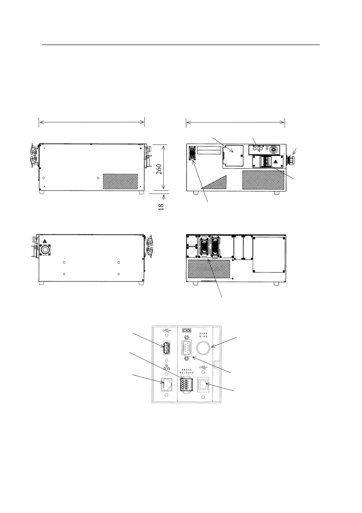
2.1 CONTROLLER APPEARANCE AND SPECIFICATION
2.1.1 APPEARANCE OF E SERIES CONTROLLERS
E01 controller
580
550
Accessory panel
Operation panel
Power input
connector
Controller
power
Left
Front
switch
Teach pendant
connector
Right
Rear
Connectors for separate harnesses
USB port
Cubic-S
Brake release
override SW (option)
connecting port
Ethernet port
RS-232C port
(Cable length: max.
30 m)
Cubic-S
USB port (option)
Connecting ports in the
accessory panel
2-2
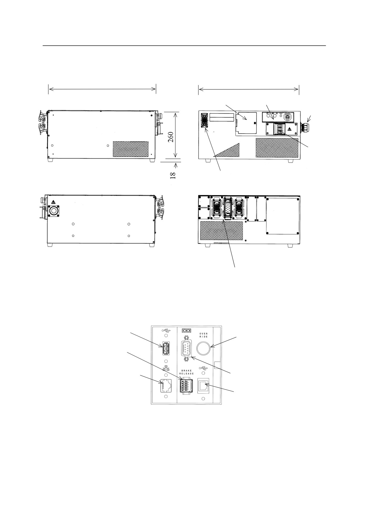
E02 controller
580
550
Accessory panel
Operation panel
Power input
connector
Controller
power
Left
Front
switch
Teach pendant
connector
Right
Rear
Connectors for separate harnesses
USB port
Cubic-S
override SW (option)
Brake release
connecting port
Ethernet port
RS-232C port
(Cable length: max. 30 m)
Cubic-S
USB port (option)
Connecting ports in the
accessory panel
2-3
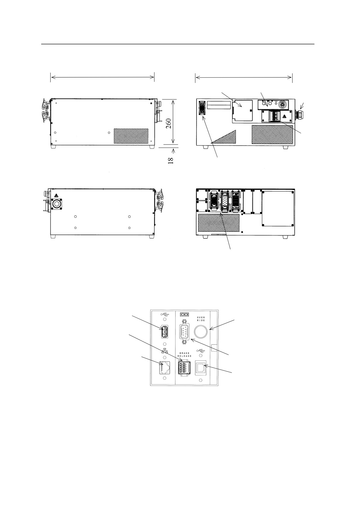
E03/E04 controllers
580
550
Accessory panel
Operation panel
Power input
connector
Controller
power
Left
Front
switch
Teach pendant
connector
Right
Rear
Connectors for separate harnesses
USB port
Cubic-S
override SW (option)
Brake release
connecting port
Ethernet port
RS-232C port
(Cable length: max. 30 m)
Cubic-S
USB port (option)
Connecting ports in the
accessory panel
2-4
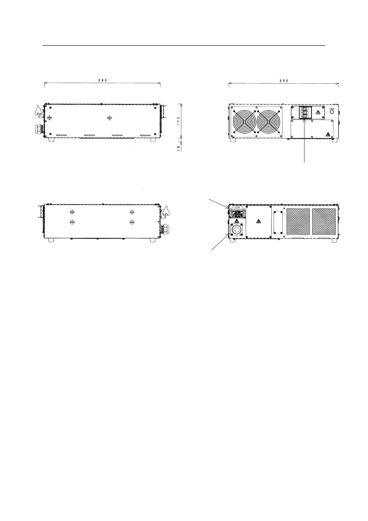
Transformer unit
Left
Front
Controller
power switch
Connector
Right
Rear
External
power inlet
2-5
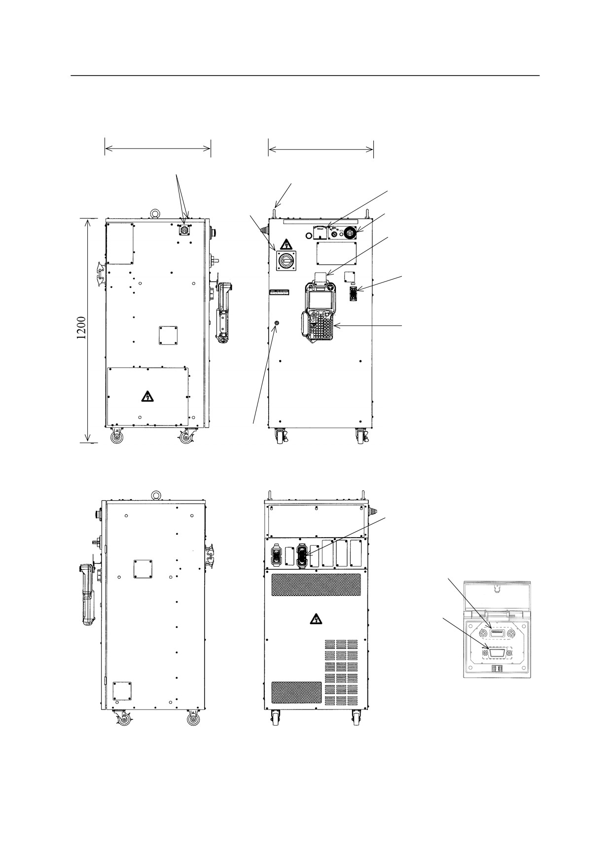
E40 controller
550
550
External power inlet
Lifting eyebolt
Accessory panel
Controller
power switch
Operation panel
Hook
Teach pendant connector
Teach pendant
Coin lock
Left
Front
Connectors for
separate harnesses㻌
USB port
RS-232C
port
Connecting ports in
the accessory panel
Right
Rear
2-6
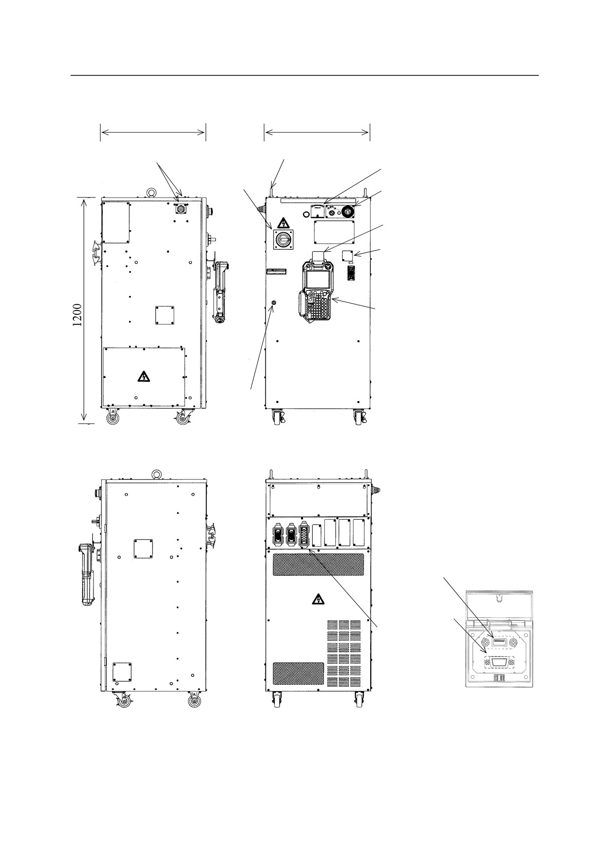
E42 controller
550
550
External power inlet
Lifting eyebolt
Accessory panel
Controller
power switch
Operation panel
Hook
Teach pendant connector
Teach pendant
Coin lock
Left
Front
USB port
RS-232C
port
Connectors for
separate
harnesses㻌
Connecting ports in
the accessory panel
Right
Rear
2-7
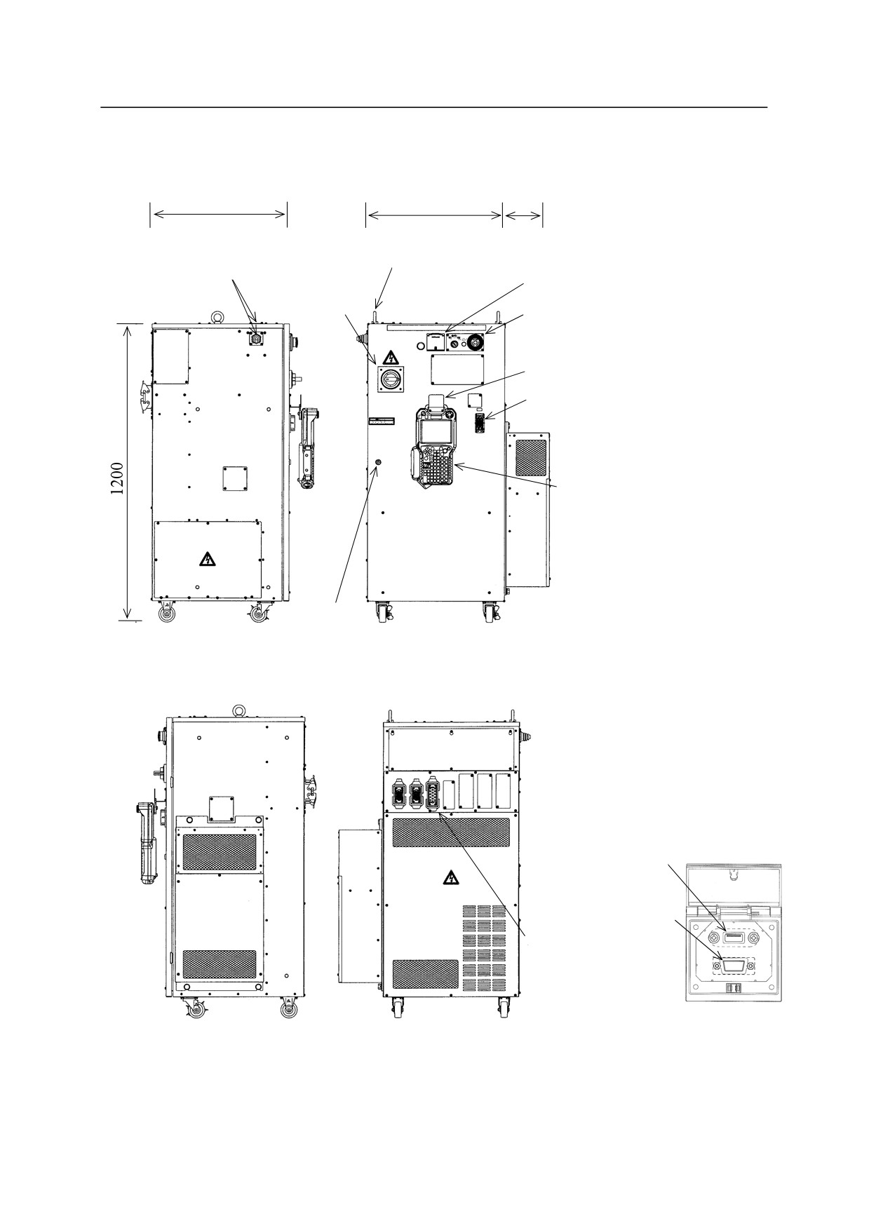
E43 controller
550
550
180
Lifting eyebolt
External power inlet
Accessory panel
Controller
power switch
Operation panel
Hook
Teach pendant connector
Teach pendant
Coin lock
Left
Front
USB port
RS-232C
port
Connectors for
separate harnesses
㻌
Connecting ports in
Right
Rear
the accessory panel
2-8
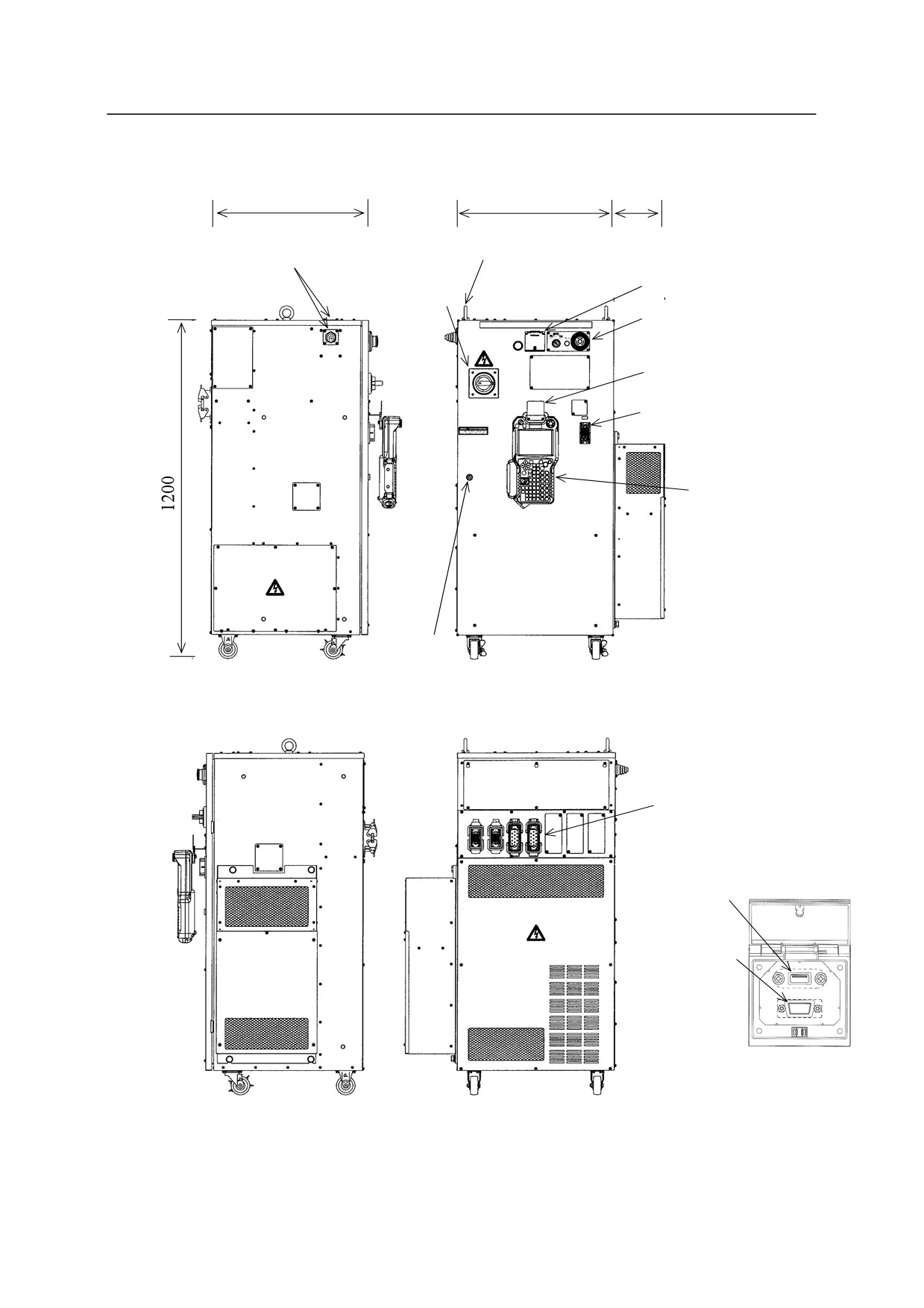
E44 controller (MD)
550
550
180
Lifting eyebolt
External power inlet
Controller
Accessory panel
power switch
Operation panel
Hook
Teach pendant connector
Teach pendant
Coin lock
Left
Front
Connectors for
separate harnesses
㻌
USB port
RS-232C
port
Connecting ports in
the accessory panel
Right
Rear
2-9
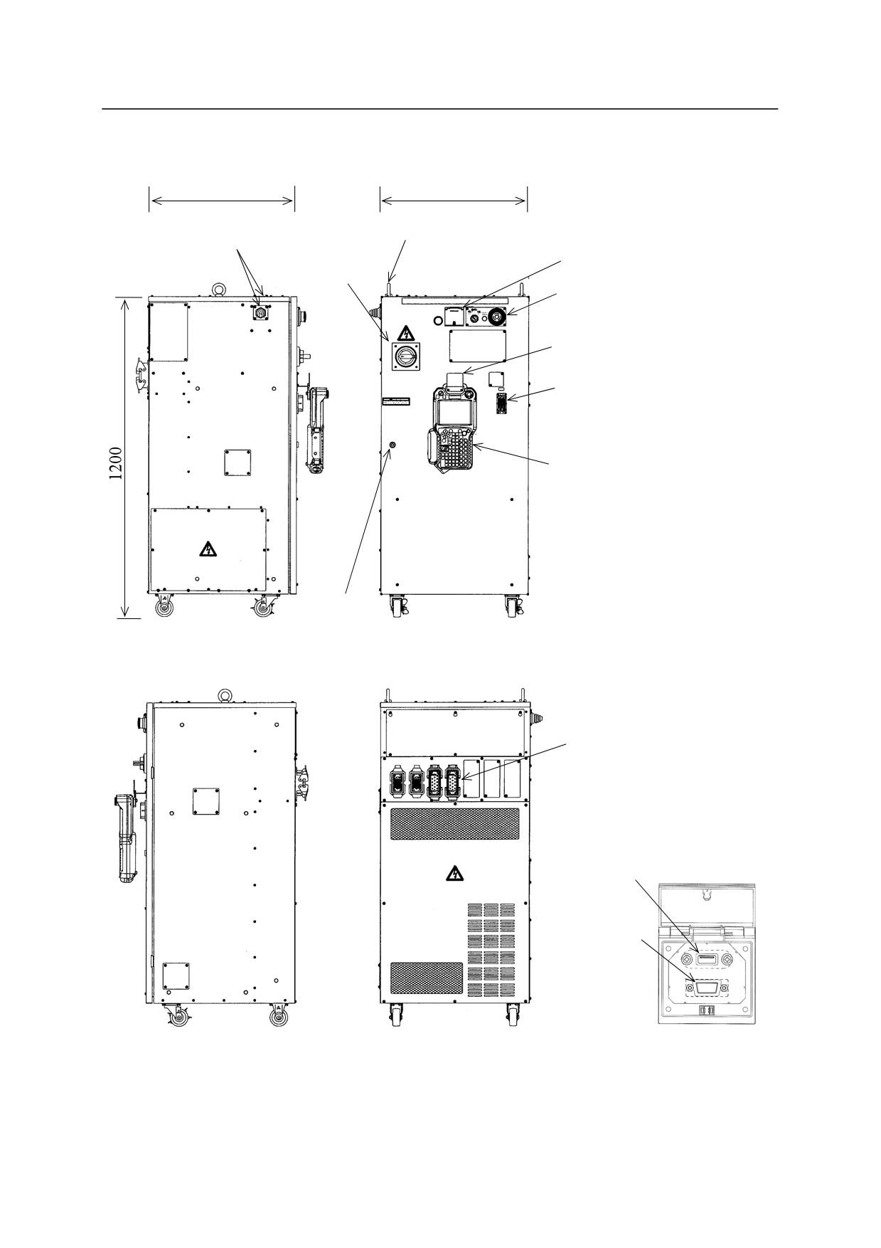
E44 controller (MX)
550
550
Lifting eyebolt
External power inlet
Controller
Accessory panel
power switch
Operation panel
Hook
Teach pendant connector
Teach pendant
Coin lock
Left
Front
Connectors for
separate harnesses
㻌
USB port
RS-232C
port
Right
Rear
Connecting ports in
the accessory panel
2-10
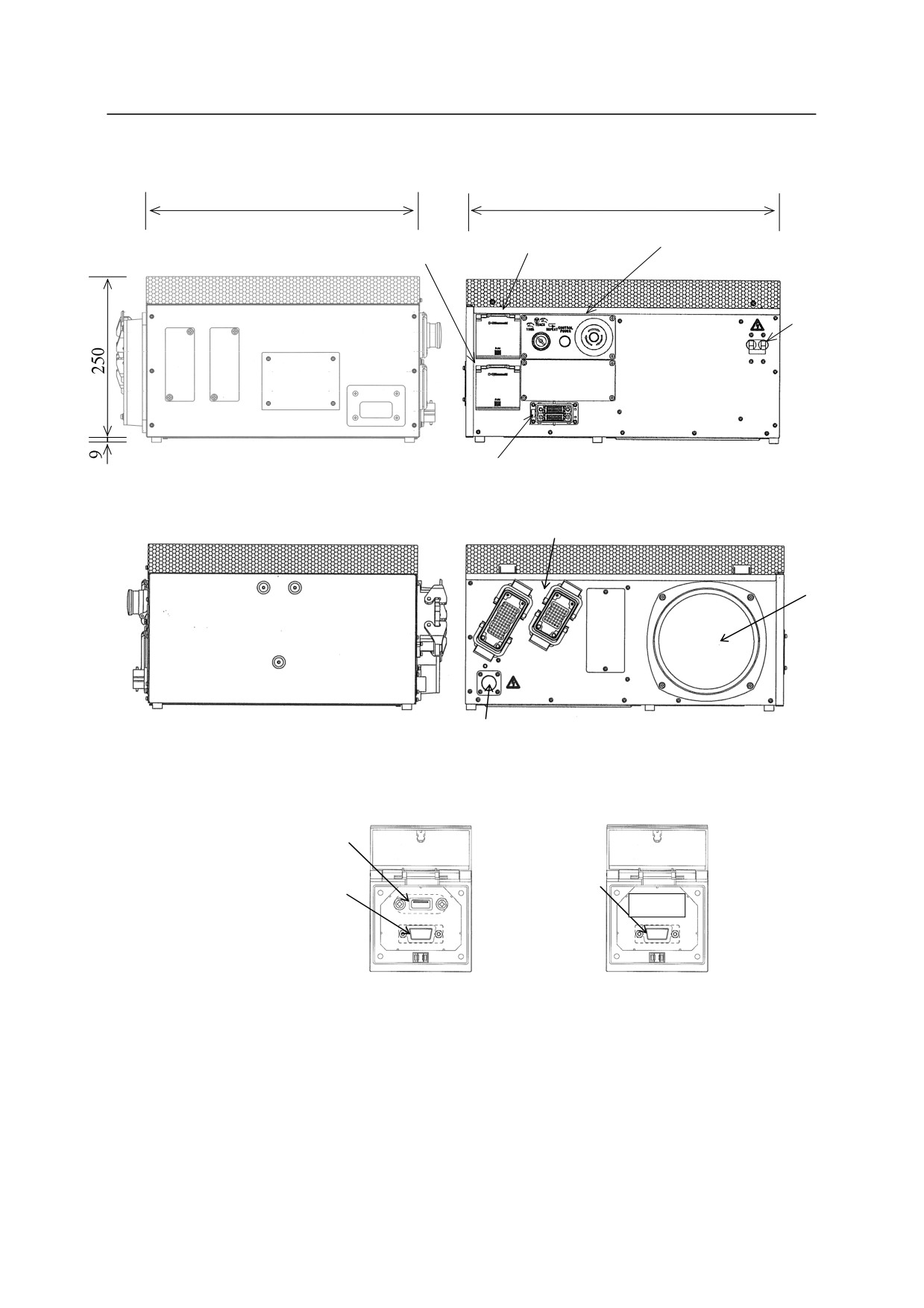
E70/E71 controllers
420
500
Accessory panel Operation panel
Brake release panel
Controller
power
switch
Left
Teach pendant connector
Front
Connector for separate harness
Heat
exchange
fan
External power
Right
Rear
inlet
USB port
Brake release
RS-232C
BRAKE
connecting port
port
Connecting ports in
Connecting port in the
the accessory panel
brake release panel
2-11
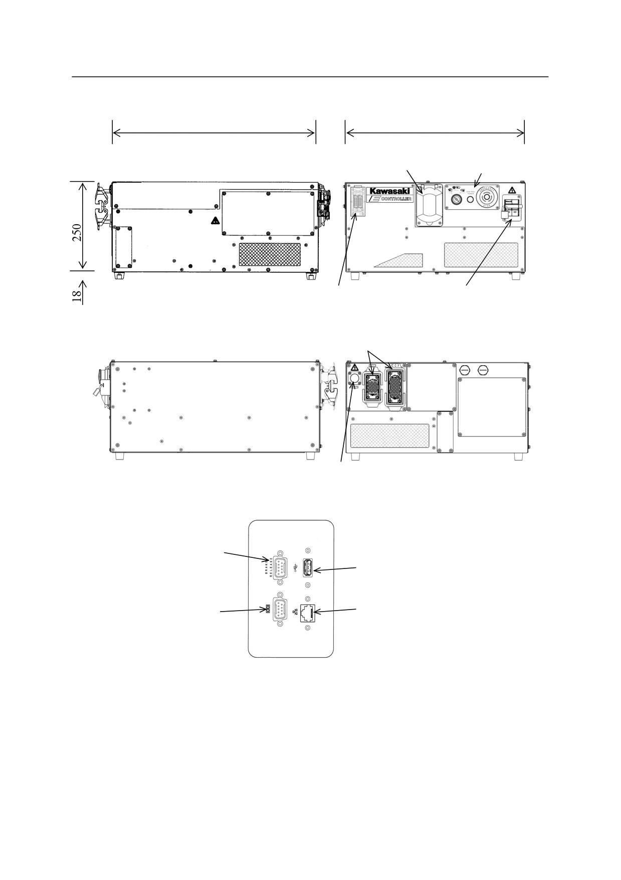
E91 controller
580
500
Accessory panel
Operation panel
Teach pendant
Controller power switch
connector
Left
Front
Connector for separate harness
External power
Right
Rear
inlet
Brake release
connecting port
USB port
RS-232C port
Ethernet port
(Cable length: max. 30 m)
Connecting ports in the accessory panel
2-12
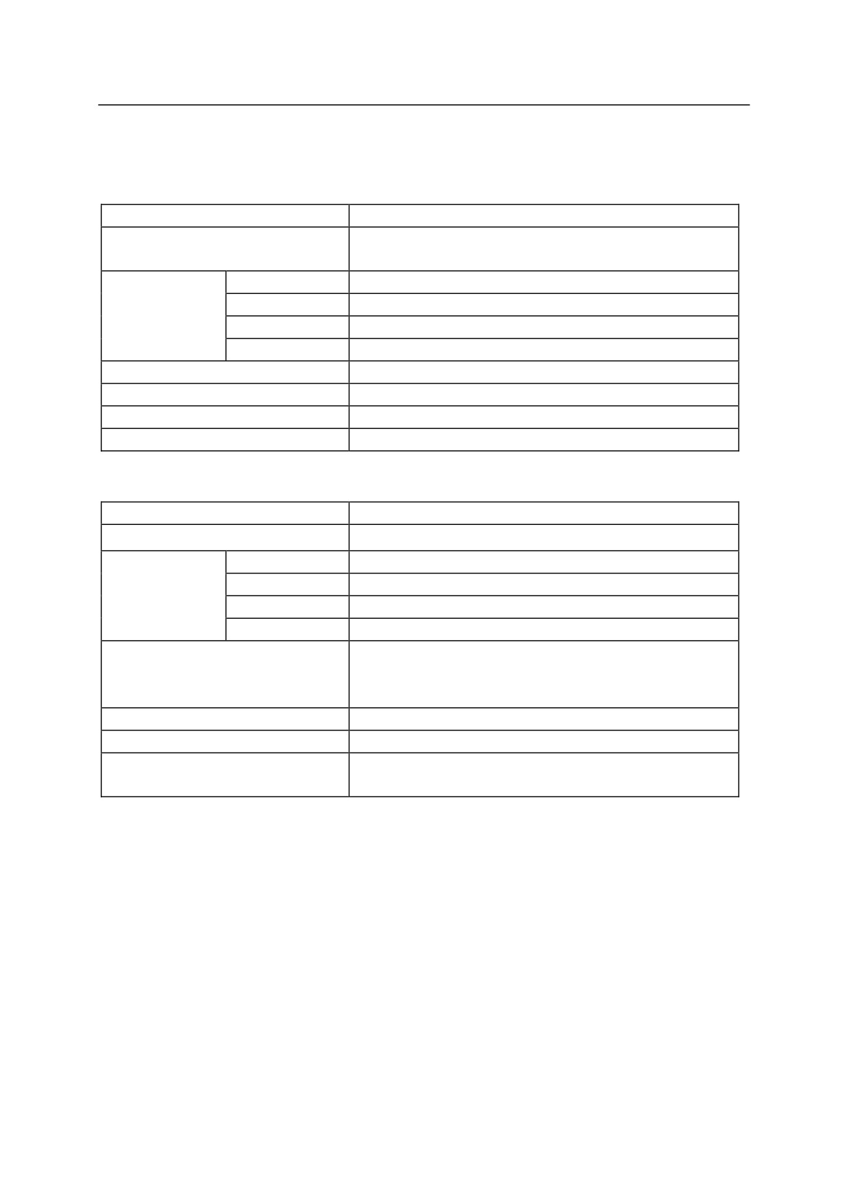
2.1.2 CONTROLLER SPECIFICATIONS
E0x controller
Construction
Enclosed structure, indirect cooling system
E01, E02, E04: 40 kg
Mass
E03: 45 kg
Temperature
0 - 45 C
Ambient
Humidity
35 - 85 %RH (Non condensing)
environment
Altitude
Up to 1000 meters above mean sea level
Pollution degree
3 or below
Power source
AC 200-220 V ±10 %, 50/60 Hz, 3 Phase
Power capacity
Refer to the table below.
Earthing
Dedicated earthing (100 or less)
Length of Teach pendant cable
5 m/10 m/15 m
Transformer unit
Construction
Enclosed structure, indirect cooling system
Mass
45 kg
Temperature
0 - 45 C
Ambient
Humidity
35 - 85 %RH (Non condensing)
environment
Altitude
Up to 1000 meters above mean sea level
Pollution degree
3 or below
AC 380-415 V㼼10 %, 50/60 Hz, 3 Phase or
Power source
AC 440-480 V㼼10 %, 50/60 Hz, 3 Phase
(Switched by voltage switching connector.)
Power capacity
Refer to the table below.
Earthing
Dedicated earthing (100 or less)
Length of connection cable with
1 m (max. 5 m for option)
controller
2-13

Controller
Arm model
Power
Recommended power cable size
Length
model
capacity
(Including earth wire)
requirement
E01
BA series
5.6 KVA
3.5 mm2 or more
200 m or less
controller
RA series
max.
(AWG #12 or more)
06L/10L/10N
20N
RS series
06L/10L/10N
20N
E02
B series
7.5 KVA
5.5 mm2 or more
200 m or less
controller
CX series
max.
(AWG #10 or more)
MT series
RS series
15X/30N/50N
80N
ZB/ZH series
ZT series
130L/130S
130U/165U
200S/200U
ZX series
130L/130S
130U/165U
200S/200U
300S
E03
CP series
12 KVA
5.5 mm2 or more
200 m or less
controller
RD series
max.
(AWG #10 or more)
E04
MX series
12 KVA
5.5 mm2 or more
200 m or less
controller
max.
(AWG #10 or more)
Transformer unit
12 KVA
5.5 mm2 or more
200 m or less
max.
(AWG #10 or more)
2-14

E4x controller
Construction
Self-sustaining fully closed, indirect cooling system
E40: 145 kg, E42, E44 (MX): 180 kg
Mass
E43, E44 (MD): 195 kg
Temperature
0 - 45 C
Ambient
Humidity
35 - 85 %RH (Non condensing)
environment
Altitude
Up to 1000 meters above mean sea level
Pollution degree
3 or below
Power source
AC 380-415 V±10 %, 50/60 Hz, 3 Phase
Power capacity
Refer to the table below.
Earthing
Dedicated earthing (100 or less)
Length of Teach pendant cable
5 m/10 m/15 m (5 m, 15 m are options.)
Length of separate harnesses*
5 m/10 m/15 m (5 m, 15 m are options.)
NOTE* Harness length between robot arm and controller.
Controller
Arm model
Power
Recommended power
Length requirement
model
capacity
cable size
(Including earth wire)
E40
RA series
4.9 KVA
3.5 mm2 or more
200 m or less
06L/10L/10N
max.
(AWG #12 or more)
RS series
06L/10L/10N/20N
YF series 03N
E42/E43
B series
9.9 KVA
5.5 mm2 or more
200 m or less
100L/100N/100S
max.
(AWG #10 or more)
130X/165L/165N
200L/250L/300L
MT series
RD series
RS series
15X/30N/50N/80N
ZB/ZD/ZH series
ZX series
130L/130S/165U/200
S/300S
E44
MD series
9.9 KVA
5.5 mm2 or more
200 m or less
MX series
max.
(AWG #10 or more)
350L/500N/700N
2-15
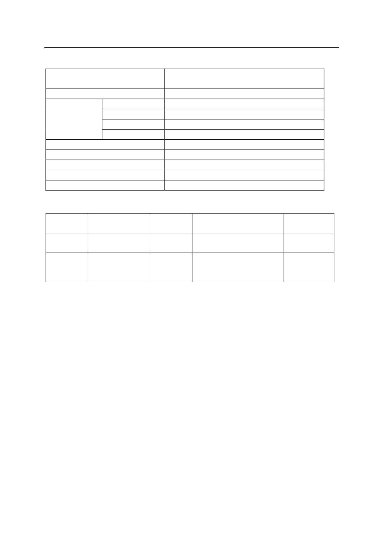
E70/E71 controllers
Horizontal enclosed structure, indirect cooling
Construction
system
Mass
30 kg
Temperature
0 - 45 C (0 - 40C in vertical placing)
Ambient
Humidity
35 - 85 %RH (Non condensing)
environment
Altitude
Up to 1000 meters above mean sea level
Pollution degree
3 or below
Power source
AC 200-240 V±10 %, 50/60 Hz, Single phase
Power capacity
Refer to the table below.
Earthing
Dedicated earthing (100 or less)
Length of Teach pendant cable
5 m/10 m/15 m (5 m, 15 m are options.)
Length of separate harnesses*
5 m/10 m/15 m (5 m, 15 m are options.)
NOTE* Harness length between robot arm and controller.
Controller
Arm model
Power
Recommended power cable
Length
model
capacity
size (Including earth wire)
requirement
E70
MC/MS series
1.5 KVA
2-2.5 mm2 or more (AWG
200 m or less
RS series 03N
max.
#14)
E71
RC series 05L
3.0 KVA
2-2.5 mm2 or more (AWG
200 m or less
RS series
max.
#14)
05L/05N/06L/10N
2-16

E91 controller
Construction
Horizontal enclosed structure, indirect cooling system
Mass
40 kg
Temperature
0 - 40 C
Ambient
Humidity
35 - 85 %RH (Non condensing)
environment
Altitude
Up to 1000 meters above mean sea level
Pollution degree
3 or below
Power source
AC 200-230 V±10 %, 50/60 Hz, Single phase
Power capacity
Refer to the table below.
Earthing
Dedicated earthing (100 or less)
Length of Teach pendant cable
5 m/10 m/15 m (5 m, 15 m are options.)
Length of separate harnesses*
5 m/10 m/15 m (5 m, 15 m are options.)
NOTE* Harness length between robot arm and controller.
Controller
Arm model
Power
Recommended power cable
Length
model
capacity
size (Including earth wire)
requirement
E91
RS series
5 KVA max.
3.5 mm2 or more
200 m or less
10L/20N
(AWG #12)
YF series
2-17
2.2 ARM SPECIFICATIONS
The motion ranges shown in the figures below are based on point P. For specifications of robot
arms not shown in this manual, see the specification sheets, delivered separately.
2-18
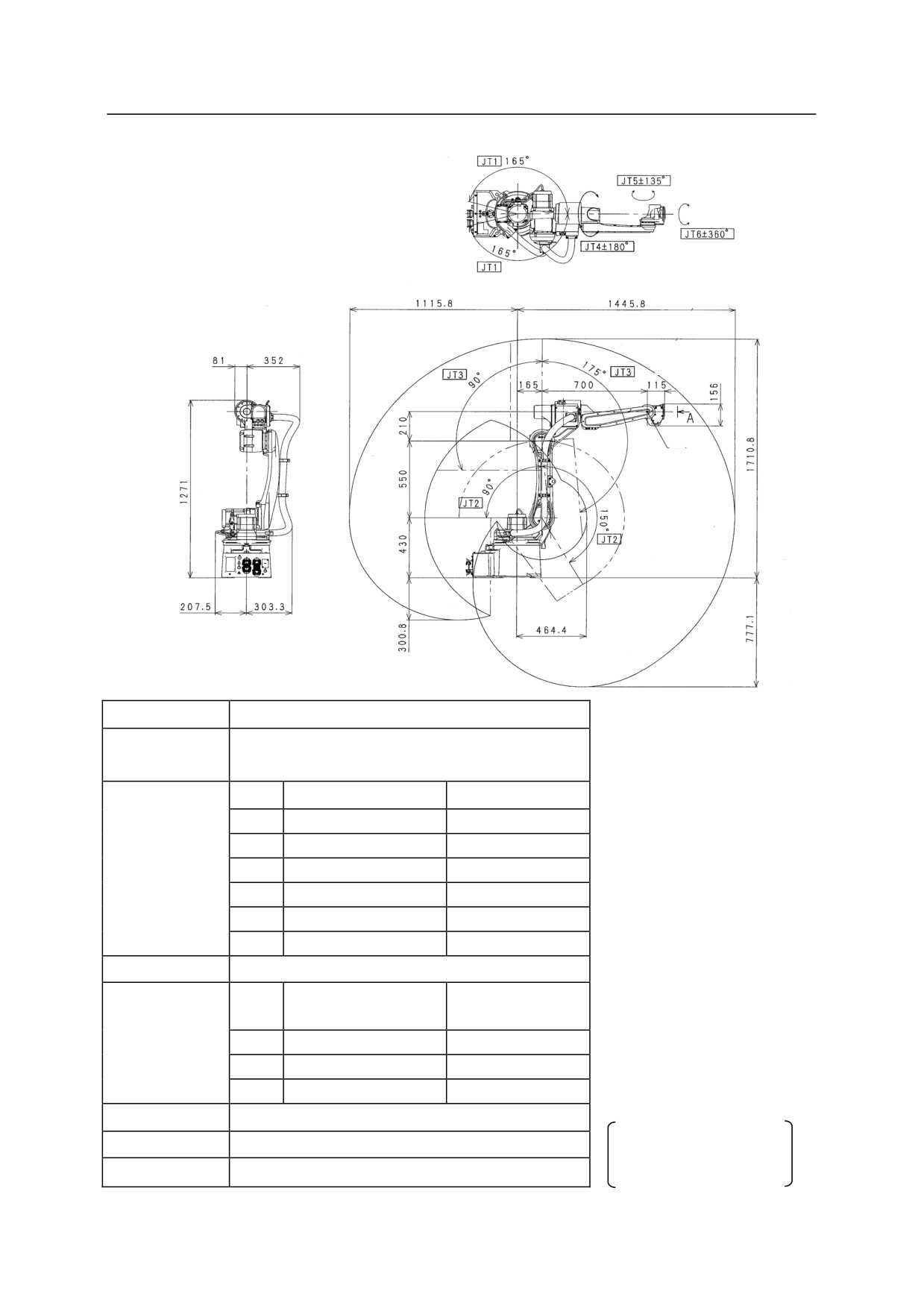
BA006N
P
Type
Articulated Robot
Degree of
6
Freedom
JT
Motion Range
Max. Speed
1
±165°
240 /s
Motion Range
2
+150° to -90°
240 /s
and
3
+90° to -175°
220 /s
Maximum
4
±180°
430 /s
Speed
5
±135°
430 /s
6
360°
650 °/s
Max. Payload
6 kg
*measured condition
Moment of
JT
Torque
・ installed on the plate
Inertia
Wrist Load
rigidly fixed on the
4
12 Nm
0.4 kgm2
Capacity
floor
5
12 Nm
0.4 kgm2
・ 3000 mm away from
6
3.75 Nm
0.07 kgm2
JT1 center
Repeatability
±0.06 mm
Mass
150 kg
Noise level depends
on the conditions.
Acoustic noise
< 70 dB (A)*
2-19
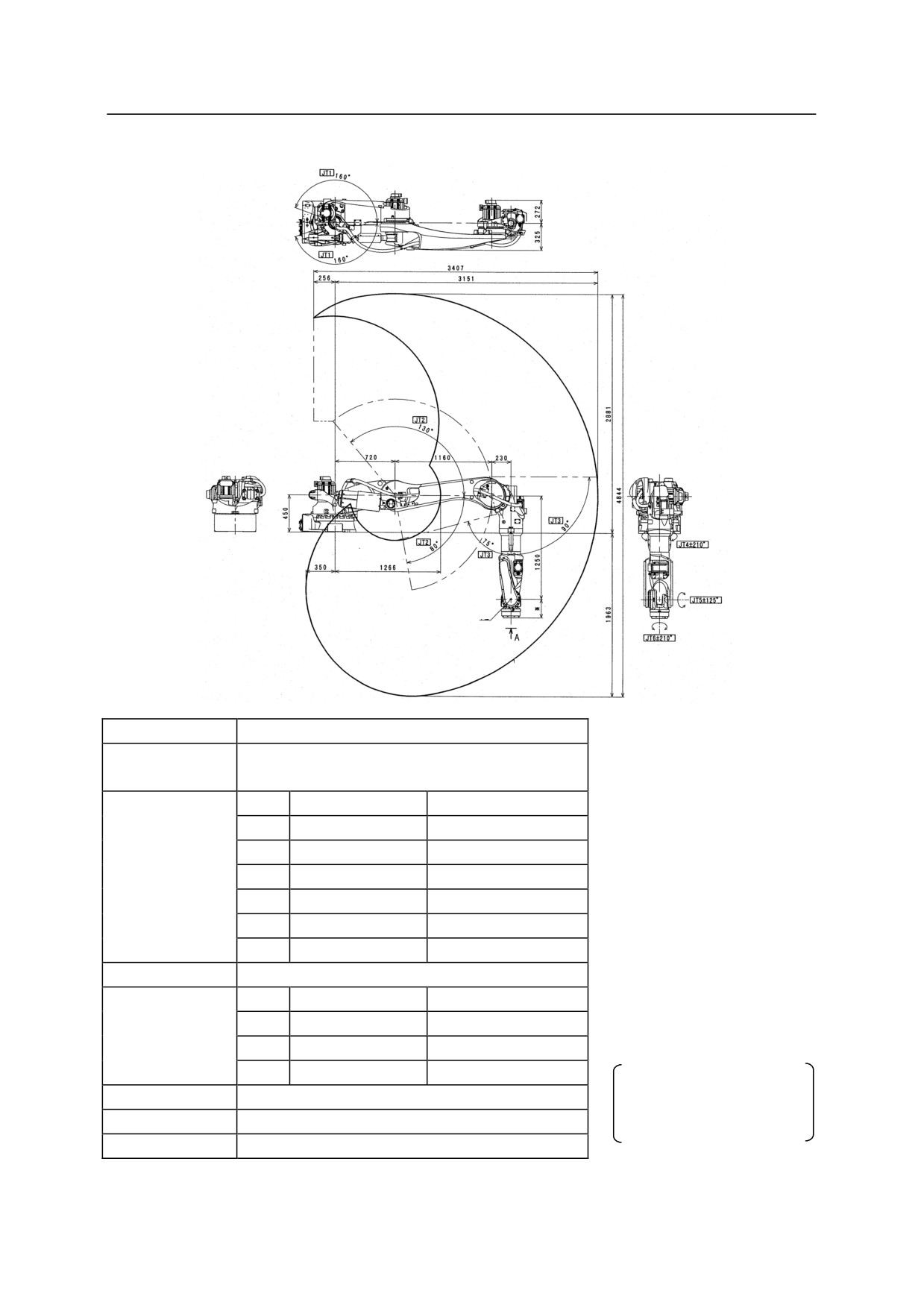
BT165L
P
Type
Articulated Robot
Degree of
6
Freedom
JT
Motion Range
Max. Speed
1
160 °
120 °/s
Motion Range
2
+80 ° to -130 °
110 °/s
and
3
+90 ° to -75 °
130 °/s
Maximum
4
210 °
170 °/s
Speed
5
125 °
170 °/s
6
210 °
280 °/s
*measured condition
Max. Payload
165 kg
・installed on the plate
JT
Torque
Moment of Inertia
rigidly fixed on the floor
・5200 mm away from JT1
Wrist Load
4
952 Nm
99 kgm2
center
Capacity
5
952 Nm
99 kgm2
6
491 Nm
49.5 kgm2
Noise level depends on
Repeatability
0.2 mm
the conditions.
Mass
1100 kg
Acoustic Noise
< 80 db (A)*
2-20
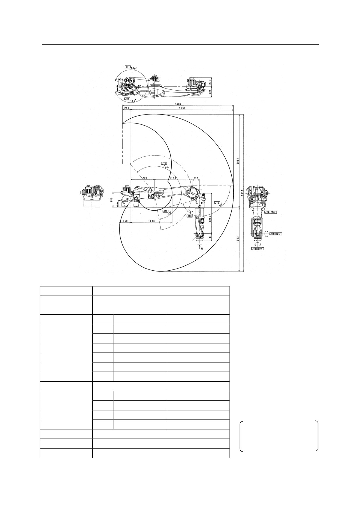
BT200L
P
Type
Articulated Robot
Degree of
6
Freedom
JT
Motion Range
Max. Speed
1
160 °
105 °/s
Motion Range
2
+80 ° to -130 °
85 °/s
and
3
+90 ° to -75 °
100 °/s
Maximum
4
210 °
120 °/s
Speed
5
125 °
120 °/s
6
210 °
200 °/s
*measured condition
Max. Payload
200 kg
・installed on the plate
JT
Torque
Moment of Inertia
rigidly fixed on the floor
Wrist Load
4
1334.0 Nm
199.8 kgm2
・5200 mm away from JT1
center
Capacity
5
1334.0 Nm
199.8 kgm2
6
588.0 Nm
154.9 kgm2
Noise level depends on
Repeatability
0.2 mm
the conditions.
Mass
1100 kg
Acoustic Noise
< 80 db (A)*
2-21
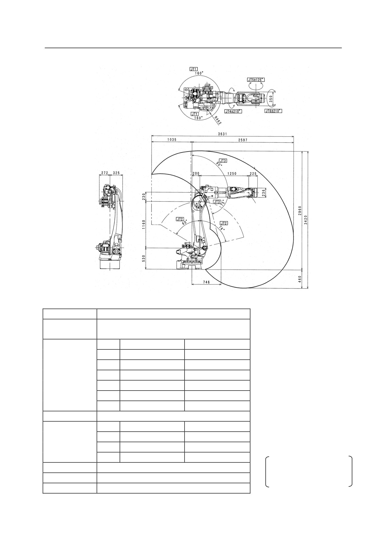
BX100L
P
Type
Articulated Robot
Degree of
6
Freedom
JT
Motion Range
Max. Speed
1
160 °
105 °/s
Motion Range
2
+76 ° to -60 °
130 °/s
and
3
+90 ° to -75 °
130 °/s
Maximum
4
210 °
200 °/s
Speed
5
125 °
160 °/s
6
210 °
300 °/s
*measured condition
Max. Payload
100 kg
・installed on the plate
JT
Torque
Moment of Inertia
rigidly fixed on the floor
Wrist Load
4
830 Nm
85 kgm2
・4600 mm away from JT1
Capacity
5
830 Nm
85 kgm2
center
6
441 Nm
45 kgm2
Noise level depends on
Repeatability
0.2 mm
the conditions.
Mass
930 kg
Acoustic Noise
< 80 db (A)*
2-22
///////////////////////////////////////