Loongson 3A3000/3B3000 processor user manual. Part ii GS464E processor core V1.2 - page 2
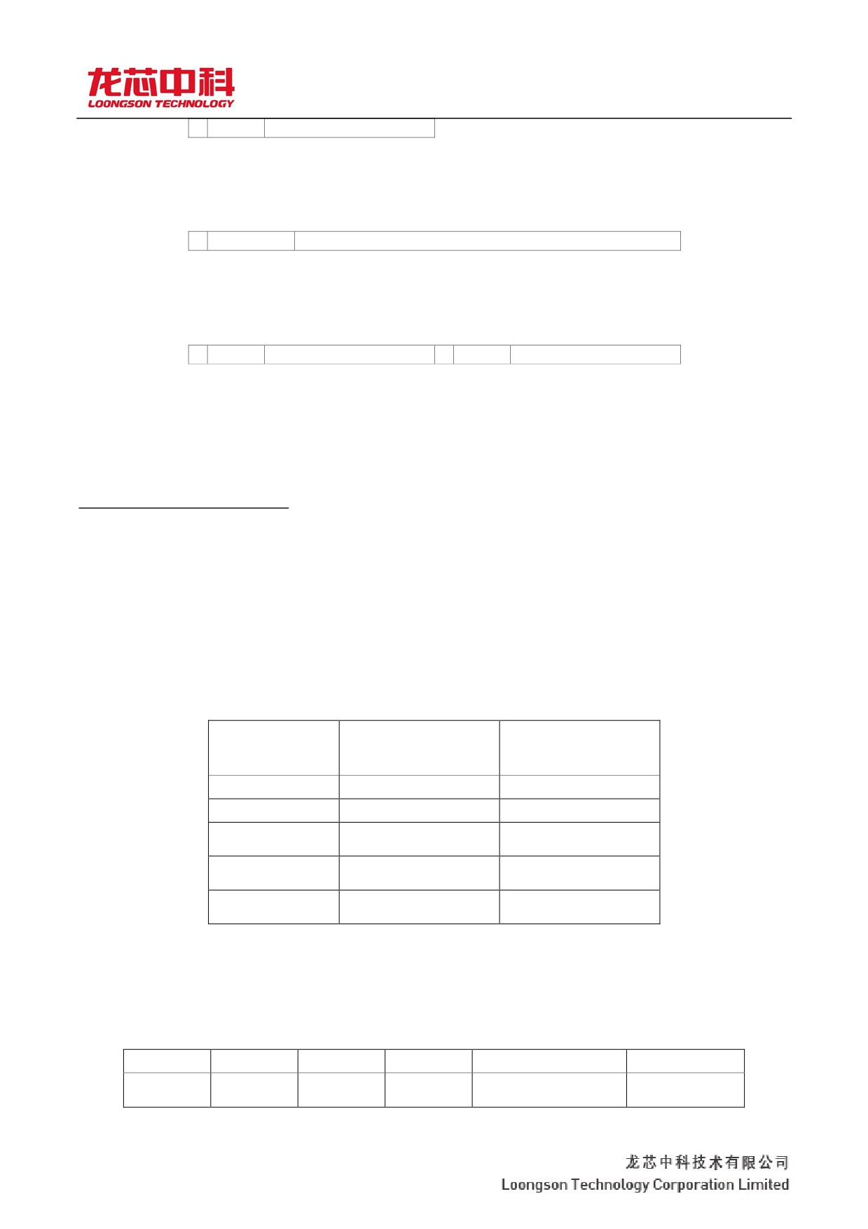
龙芯 3A3000/3B3000 处理器用户手册 y 下册
s.
Exponent
Fraction
1823
Single precision floating point number (S)
6
6
5 5
0
3
2
2 1
s.
Exponent
Fraction
11152
Double floating-point number (D)
6
6
5 5
3 3 3
2 2
0
3
2
5, 4
2 1 0
3 2
s.
Exponent
Fraction
s.
Exponent
Fraction
1
8
23
1
8
23
Paired single precision floating point Numbers (PS)
The floating point format consists of three fields:
y The symbol field, S
y The index field with deviation, e = e + Bias, e is the index without deviation
The decimal region, F =.bb... 12 B - p1
The range of the exponent E without offset is the integer between all Emin and Emax plus the following two
reserved values:
y Emin-1 (used to encode 0 and nonnormalized Numbers)
y Emax +1 (used to encode infinity and NaN[Not a
Number]) Table 2-13 defines the values of the
parameters associated with the floating-point format.
Table 2-13 floating point format parameters
paramete
Single
double
r
precisi
on
Emax
+ 127
+ 1023
Emin
- 126.
- 1022.
Exponential
+ 127
+ 1023
offset
Index bits
8
11
wide
Small digital
24
53
wide
For single - or double-precision formats, each non-zero number that can be represented has a unique code
corresponding to it. The calculation method of the value V corresponding to its encoding is shown in Table 2-14.
Table 2-14 Calculation of floating point values V
E
F
s.
b1
V
x
1
SNaN (Signaling
E + 1 max
Ind
NaN)
15
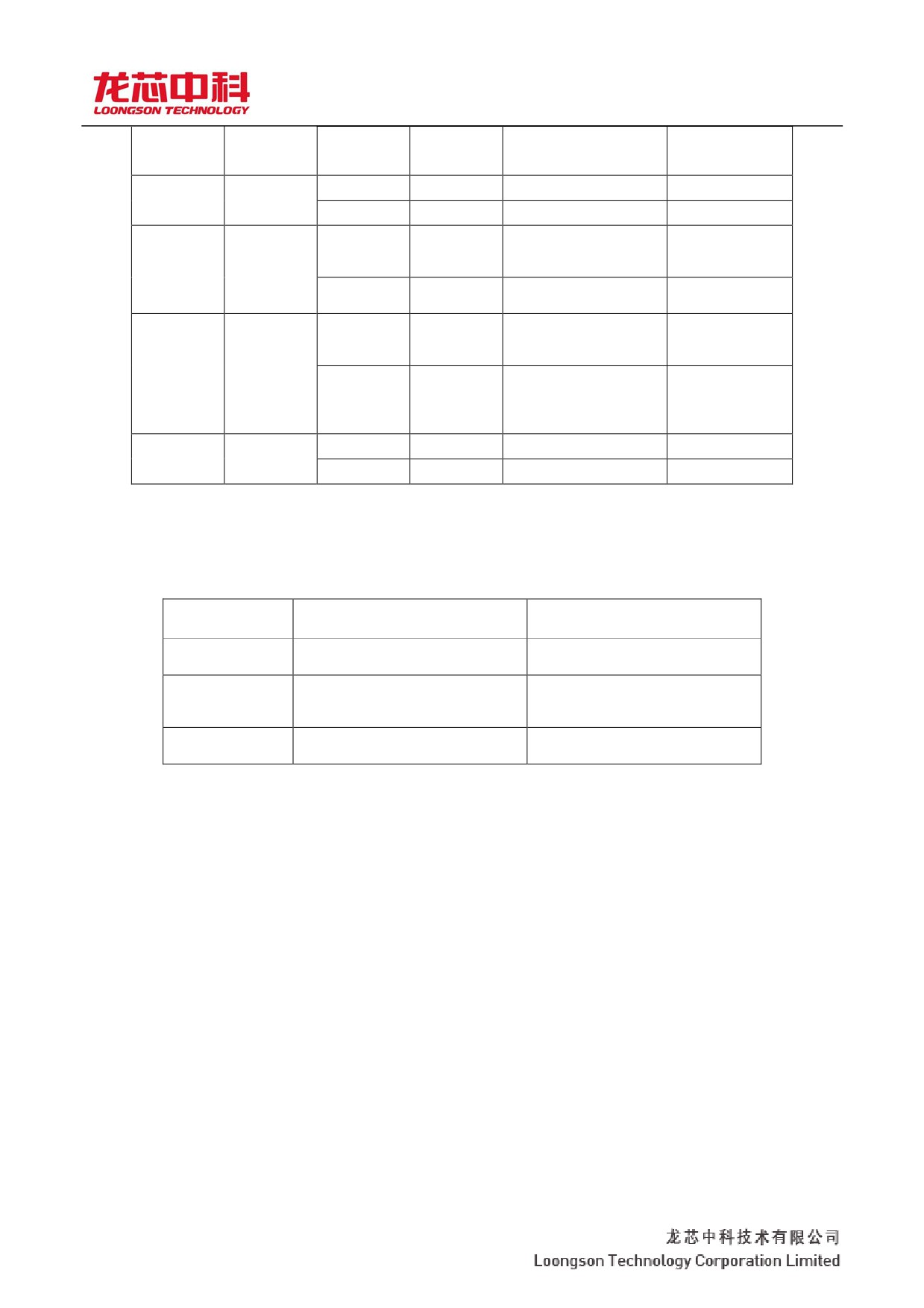
龙芯 3A3000/3B3000 处理器用户手册 y 下册
icat
x
0
QNaN (Quiet NaN)
es
a 0
1
x
- up
Minus infinity
E + 1 max
0
0
x
+ up
Is infinite
1
x
- (2) (1 F) E
Negative
[Emin, Emax]
x
normalized
Numbers
0
x
+ (2) (1 F) E
Normalized
Numbers
1
x
. - (2) (0 F) Emin-1
Negative
E - 1 min
Ind
disnormalized
icat
Numbers
es
0
x
. + (2) (0 F) Emin-1
Positive and
a 0
non-
normalized
Numbers
1
x
0
Negative zero
E - 1 min
0
0
x
+ 0
Is zero
The maximum and minimum values of the two types of floating-point Numbers are given in Table 2-15.
Table 2-15 Maximum and minimum floating-point values
type
Single
double
precision
The minimum
1.40129846 e -
4.9406564584124654 e -
number of
45
324
Minimum
1.17549435 e -
2.2250738585072014 e -
normalized
38
308
number
Maximum
3.40282347 e
1.7976931348623157
number
e+308
Fixed point data type
Fixed-point data supported by FPU are all signed integers and can be divided into two types:
y
32-bit signed integer (Word, W)
16
龙芯 3A3000/3B3000 处理器用户手册 y 下册
y The format of the two fixed-point data types of
64-bit signed Longword (L) is shown in Figure 2-2.
Figure 2-2 FPU fixed-point data format
330
10
s.
The
I t
131
Signed integer (W)
660
32
s.
The
163
Signed long word integer (L)
2.2.2 Floating point register
Floating-point registers in GS464E inherit the MIPS R4000/R10000 processor usage, which is slightly
different from the MIPS64 specification. When the FR bit of the Status control register is 0, GS464E has only 16
32-bit or 64-bit floating-point registers, and the floating-point register Numbers must be even. while
The MIPS64 means there are 32 32-bit floating point registers or 16 64-bit floating point registers. When the
FR bit of the Status control register is 1,
The GS464E USES floating-point registers in the same way as the MIPS64 specification, with 32 64-bit
floating-point registers.
2.2.3 Floating point control register
Floating point control registers in GS464E include:
y FIR, floating point implementation to define registers
y FCCR, floating point conditional code register
y FEXR, floating point exception register
y FENR, floating point enable register
y FCSR, floating point control/state register (often called FCR31)
Access to floating point control registers does not require a kernel mind. The software accesses the floating
point control register through CFC1 and CTC1 instructions. In the floating point control registers mentioned above,
the access registers FCCR, FEXR, and FENR actually access some of the domains of FCSR.
Floating point implementation define Register (FIR, CP1 Control Register 0)
The floating-point implementation definition register is a 32-bit read-only register that contains the functions
of the floating-point unit implementation, such as processor ID, revision number, and so on.
Figure 2-3 illustrates the FIR register format; Table 2-16 describes each FIR register field.
17

龙芯 3A3000/3B3000 处理器用户手册 y 下册
Figure 2-3 FIR register format
31
23
22
21
20
19
18
17
16
15
8
7
0
0
F64
L
W.
Th
PS
D
s.
ProcessorID
Revision
e 3
d
Table 2-16 Description of FIR register fields
Domain
positio
Function
Read/
Reset
name
n
al
write
value
descripti
on
18
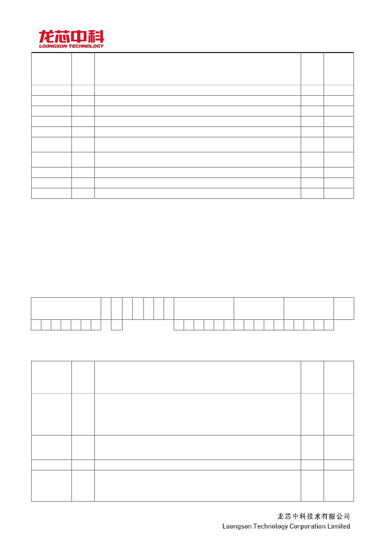
龙芯 3A3000/3B3000 处理器用户手册 y 下册
Domain
positio
Function
Read
Reset
name
n
al
/writ
value
descripti
e
on
0
31.. 23
Read only is always 0.
0
0
F64
22
A constant of 1 indicates that the floating-point data path is 64-bit.
R
0 x1
L
21
Constant is 1, indicating the implementation of long word (L) fixed-point data type.
R
0 x1
W.
20
Constant is 1, indicating the implementation of the word (W) fixed-point data type.
R
0 x1
The 3 d
19
Constant 0 indicates that MIPS 3D ASE has not been implemented.
R
0 x0
PS
18
Constant 1 means that a pair of single-precision floating point data types are
R
0 x1
implemented.
D
17
A constant of 1 means that the double precision floating point data type is
R
0 x1
implemented.
s.
16
A constant of 1 means that a single precision floating point data type is implemented.
R
0 x1
ProccsorID
15.. 8
Floating-point coprocessor identifier.
R
0 x05
Revision
7.. 0
Floating-point coprocessor version number.
R
0 x01
Floating point Control and Status Register (FCSR, CP1 Control Register 31)
The FCSR register is used to control the operation of the floating point unit and to represent some state.
Figure 2-4 illustrates the FIR register format; Table 2-17 describes each FIR register field.
Figure 2-4. FCSR register format
31
30
29
28
27
26
25
24
23
22
21
20
19
18
17
16
15
14
13
12
11
10
9
8
7
6
5
4
3
2
1
0
The FCC
Th
The
0
TOP 0
0
0
Cause
Enables
Flags
The
e
FCC
RM
FS
7
6
5
4
3
2
1
0
E
V
Z
O
U
i.
V
Z
O
U
i.
V
Z
O
U
i.
Table 2-17 Describes the FCSR register fields
Domain
positio
Function
Read
Reset
name
n
al
/writ
value
descripti
e
on
Floating point conditional code. Records floating-point comparison results for
31.. 25
conditional jumps or transitions. When a floating-point comparison operation is
The FCC
R/W
0 x0
23,
performed
When it occurs, the result is saved in the specified CC bit, the conditional bit. If the
comparison is true, the CC bit is set to 1; If not, set 0.
Brush to the 0 identification bit. When set to 1, the nonnormalized result is set to 0.
The FS
24
R/W
0 x0
Otherwise the result is nonnormalized
The number will trigger an unimplemented exception.
0
22
Read only is always 0.
0
0
Floating point register TOP mode control bit. When the bit is 1, the register
TOP
21
R/W
0 x0
representing the floating-point instruction takes TOP
The way the pattern is encoded; When the bit is 0, the register representing the floating-point
instruction is still encoded in the normal way.
14
龙芯 3A3000/3B3000 处理器用户手册 y 下册
0
20.. 18
Read only is always 0.
0
0
15

龙芯 3A3000/3B3000 处理器用户手册 y 下册
Domain
positio
Function
Read
Reset
name
n
al
/writ
value
descripti
e
on
These bits reflect the results of the most recent instruction execution. The Causes
field is a logical extension of the coprocessor's 0 Cause register, and these bits
indicate the exception caused by the last floating-point operation and produce an
interrupt or exception if the corresponding Enable bit is set. If more than one
Cause
17.. 12
R/W
0 x0
exception is produced in an instruction, each corresponding exception causes the bit
to be set.
The Causes field can be overridden by every floating-point operation instruction (not
including Load, Store, and Move). If software simulation is needed to complete, the
unrealized operation bit (E) of the operation will be set to 1; otherwise, it will remain at 0. The
other bits are set to 1 or 0 according to the IEEE754 standard depending on
whether the corresponding exception is made.
When a floating point exception occurs, no result will be stored, and the only state
affected is the Causes field.
Any time the Cause and the corresponding Enable bit are both 1, a floating
point exception is generated. If a floating point operation sets a Cause that is allowed to
be activated (with the corresponding Enable bit of 1), the processor immediately makes an
exception, just as if the CTC1 instruction were used to set the Cause bit and Enable bit to 1 at
the same time.
There is no enabling bit for unimplemented operation (E), which always produces a
Enables
11.. 7
floating point exception if set.
R/W
0 x0
Before returning from a floating point exception, the software must first clear the
activated Cause with a CTC1 instruction to prevent the repeated execution of the
interrupt. Thus, a program running in user mode will never observe that the value of
the enabled Cause is 1; If the user-mode handler needs to get this information, the contents
of the Cause must be passed somewhere other than in the status register.
If a floating-point operation sets only the Cause that is not enabled (the corresponding
enabled bit is 0), no exceptions occur, and the default result defined by the IEEE754
standard is written back. In this case, the previous floating point
Causes the exception to be determined by reading the value of the Causes field.
The flag bits are cumulative, indicating that an exception has occurred since the last time they were
explicitly reset. If an EEE754 exception is generated, the corresponding Flag bit is set to 1, otherwise it
Flags
6.. 2
R/W
0 x0
remains unchanged, so the bits are never cleared for floating point operations. But we can write a
new value to the state with the CTC1 command
Register to set or clear Flag bits.
The RM
1.. 0
Rounding - in mode control domain. Table 2-18 further describes the encoding of RM.
R/W
0 x0
Table 2-18 Rounding mode (RM) encoding
Roundin
mnemo
desc
g mode
nics
ribe
(RM)
Rounding the result in the direction closest to the representable number, the
0
RN
result is the same when the two nearest representable Numbers are separated
When approaching, round off to the nearest number direction with the lowest
value of 0.
Rounding in the 0 direction: rounding the result to the nearest number and not greater than it in absolute value
1
RZ
Into the.
16
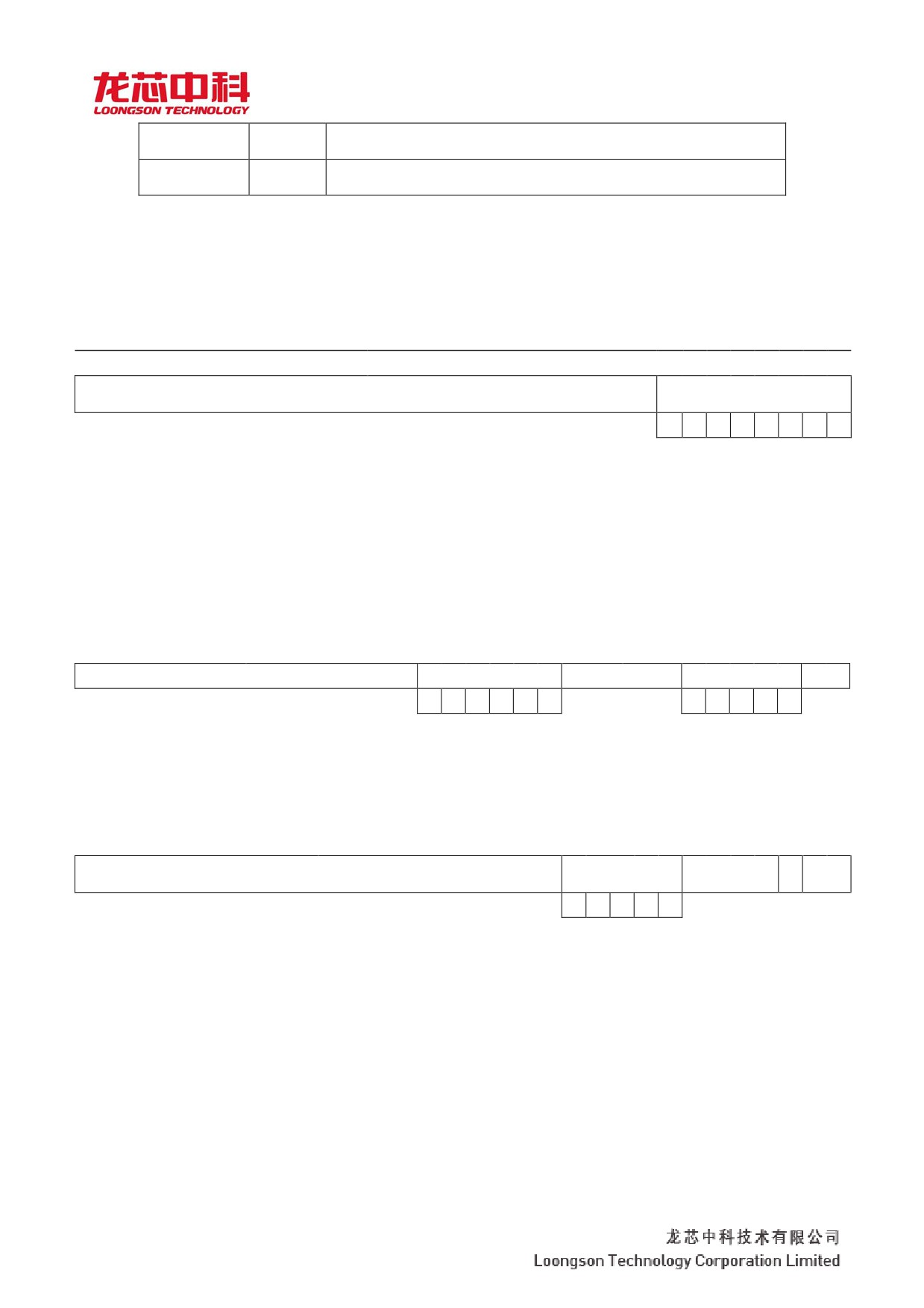
龙芯 3A3000/3B3000 处理器用户手册 y 下册
2
The RP
Round off in the direction of positive infinity: round off the result to the number
closest to and not less than it.
3
The RM
Round off in the direction of negative infinity: round off the result to the
number closest to and not greater than it.
Floating point conditional code Register (FCCR, CP1 Register 25)
The FCCR register is another way to access the FCC field. Its content is exactly the same as the FCC bit in
FCSR, except that the FCC bit in this register is continuous. Figure 2-5 illustrates the format of the FCCR register.
Figure 2-5 FCCR register format
31
8
7
6
5
4
3
2
1
0
The
FCC
7
6
5
4
3
2
1
0
Floating point Exception Register (FCCR, CP1 Register 26)
The FEXR register is another way to access the Cause and Flags fields, and its contents are identical to the
corresponding fields in FCSR. Figure 2-6
The format of the FEXR register is explained.
Figure 2-6 FEXR register format
31
18
17
16
15
14
13
12
11
7
6
5
4
3
2
1
0
Cause
Flags
E
V
Z
O
U
i.
V
Z
O
U
i.
Floating-point Enable Register (FCCR, CP1 Register 28)
The FENR register is another way to access Enable, FS, and RM fields. Figure 2-7 illustrates the FENR
register format. Figure 2-7 FENR register format
31
12
11
10
9
8
7
6
5
4
3
2
1
0
Enables
The
The
FS
RM
V
Z
O
U
i.
2.2.4 Floating-point exception
Floating point exceptions occur when the FPU does not handle operands or the results of floating point
calculations in a regular way, and the FPU produces an exception to start the software trap or to set the status flag
bit.
The control and state registers of the FPU contain an enablement bit for each exception that determines
whether an exception can cause the FPU
Start an exception trap or set a status flag.
17
龙芯 3A3000/3B3000 处理器用户手册 y 下册
If a trap is started, the FPU reserves the operation in the starting state and starts the software exception
processing path. If no trap is started, an appropriate value is written to the FPU target register and the calculation
continues.
FPU supports five IEEE754 exceptions:
y Inexact. Inexact (I)
y Underflow Underflow (U)
y Overflow Overflow (O)
y Division by Zero (Z)
y Invalid Operation (V)
And the sixth exception:
y Unimplemented Operation (E)
Unimplemented operation exceptions are used when the FPU cannot perform the standard MIPS floating point
structure, including when the FPU cannot determine the correct exception behavior. This exception indicates the
execution of the software exception handling. An unimplemented exception has no enabling signals and flag bits,
and when this exception occurs, a corresponding unimplemented exception trap occurs.
18
龙芯 3A3000/3B3000 处理器用户手册 y 下册
Each of the five exceptions to IEEE754 (V, Z, O, U, I) corresponds to a user-controlled exception trap that is
allowed to occur when one of the five enabling bits is set. When an exception occurs, the corresponding Cause bit
is set. If the corresponding Enable bit is not set, the exception Flag bit is set. If the enable bit is set, the flag bit is
not set, and the FPU produces an exception to the CPU. Subsequent exception handling allows the exception trap
to occur.
When there is no exception trap signal, the floating-point processor handles it by default, providing an
alternate value for the result of the floating-point calculation. Different exception types determine different default
values. Lists the FPU default handling for each IEEE exception.
Table 2-19 Default handling of floating point exceptions
The
describe
Rounding
The
domain
mode
default
action
i.
The
Any pattern
Provide rounded results
precise
RN
Set the result to 0 according to the sign of the intermediate
result
U
underflow
RZ
Set the result to 0 according to the sign of the intermediate
result
The
Correct positive underflow to a minimum positive number
RP
and negative underflow to minus 0
The
Correct the negative underflow to the minimum negative
RM
number, and correct the positive underflow to +0
RN
Set the result to infinity according to the sign of the
intermediate result
O
The
RZ
Set the result to the largest number according to the sign of
overflow
the intermediate result
The
Correct the negative underflow to a maximum negative
RP
number, and correct the positive underflow to +∞
The
Correct positive underflow to the largest integer and
RM
negative underflow to minus infinity
Z
Be zero
Any pattern
Provides a corresponding signed infinite number
except
V
Illegal
Any pattern
Provide a Quiet Not a Number(QNaN)
operation
The conditions that cause the FPU to produce each exception are described below, and the FPU's response to
each exception's cause condition is detailed. Imprecise exception (I)
The FPU produces an imprecise exception when:
y Rounding results are imprecise
y The rounding result overflows
y Rounding results underflow, and the underflow and imprecise enablement bits are not set, and the FS bits are set.
Trap enabled results: If an imprecise exception trap is enabled, the result register is not modified, and the
source register is retained. Because this pattern of execution affects performance, the imprecise exception trap is
enabled only when necessary.
Trap unenabled results: If no other software trap occurs, rounding or overloading results are sent to the target
17
龙芯 3A3000/3B3000 处理器用户手册 y 下册
register. Illegal Operation Exception (V)
The illegal operation exception signals when two or one of the operands of an executable operation is illegal.
If the exception does Not fall, MIPS defines the result as a Quiet Not a Number (QNaN). Illegal operations include:
y Addition or subtraction: infinite subtraction. For example, (+∞)+(-∞) or (-∞)-(- ∞).
y Multiplication: 0 times infinity, for all positive and negative Numbers
y Division: 0 over 0, infinity over infinity, for all positive and negative Numbers
y The number of comparison operations that do not process Unordered is Unordered
y Performs a floating-point comparison or conversion on an indicator, NaN
y Any mathematical operation for SNaN (Signaling NaN). When one of the operands is SNaN or both of them are SNaN
18
龙芯 3A3000/3B3000 处理器用户手册 y 下册
Causes this exception (MOV operations are not considered mathematical operations, but ABS and
NEG are considered mathematical operations)
y
Square root of X, when X is less than 0
Software can simulate exceptions to other illegal operations for a given source operand. For example, in
IEEE754, software is used to realize a specific function: X REM Y, where Y is 0 or X is infinite; Or overflows
when floating point Numbers are converted to decimal, which is infinity or NaN; Or a prior function like ln of 5 or
cosine of 3. -1
Trap enabled result: The value of the source operand is not sent.
The trap does not enable the result: If no other exception occurs, QNaN is sent to the target register. Except
zero (Z)
In a division operation, the exception to zero signals when the divisor is zero and the dividend is a finite non-
zero data. Software can be used to simulate all but zero exceptions for other operations that produce signed infinity
values, such as ln(0), sin(/2), cos(0), or 0. -1
Trap enabled: The result register is not modified and the source register is retained.
Trap non-enabling: If no trap occurs, the result is a signed infinity. Overflow exception (O)
When the magnitude of the rounded floating-point result is represented by an unbounded exponent, larger than
the finite data represented by the maximum target pattern, the overflow exception signals the notification. (This
exception sets both imprecise exceptions and flags.)
Trap enabled: The result register is not modified and the source register is retained.
Trap non-enablement: If no trap occurs, the final result is determined by the symbol of the rounding pattern
and the intermediate result. Downflow exception (U)
Two related events lead to the downflow exception:
y A small non-zero result between ±2Emin, which is so small that it leads to a downflow exception.
y Severe data distortion approximated by a Denormalized Number from the two small Numbers. IEEE754
allows many different ways to detect these events, but requires the same method for all operations. Little
data
It can be detected in one of the following ways:
y After rounding (if a non-zero data is calculated without a bound in the exponential range, it should be
strictly between ±2Emin)
y Pre - rounding (if a non-zero data is calculated without boundaries between exponential and precision ranges, it should
be strictly within ±
Between 2 emin)
The structure of MIPS requires small data to be detected after rounding. Accuracy distortion can be detected
in one of the following ways:
y The distortion of a nonnormalized number (when the resulting result is different from that calculated when the
19
龙芯 3A3000/3B3000 处理器用户手册 y 下册
exponent is not bounded)
y Imprecise data (when the resulting results are not bounded by the exponential and precision ranges)
MIPS structures require precision distortion to be detected to produce inaccurate results.
Trap enabled: If an overflow or imprecise exception is enabled, or if the FS bit is not set, an unimplemented
exception is generated and the result register is not modified.
Trap not enabled: If overflow or imprecise exceptions are not enabled, and the FS bit is set, the final result is
determined by the symbol bit of the rounding mode and the immediate result.
Unimplemented operation Exception (E)
Unimplemented operation in the FPU control/state register when any of the opcodes or operation format
instructions reserved for future definitions are executed
20
龙芯 3A3000/3B3000 处理器用户手册 y 下册
Action causes bits to be set and traps are created. The source operands and destination registers remain
unchanged while the instructions are simulated in the software. Any exception in IEEE754 can be generated from a
simulation operation, and these exceptions can in turn be simulated. In addition, exceptions to unimplemented
instructions can occur when the hardware fails to perform some rare operation or result condition correctly. These
include:
y Nonnormalized Operand, except for comparison instructions
y Quite Not a Number operand (QNaN), with the exception of comparison instructions
y Nonnormalized Numbers or underflows, and overflows or imprecise enabling signals are set while FS bits are not set
Note: disnormalized Numbers and NaN operations only fall into traps in conversion or computation
instructions, not in MOV instructions. Trap enabled: The original operation data is not sent.
Trap unenabled: This trap cannot be unenabled.
2.2.5 MIPS64 is compatible with floating point instruction list
The relevant instructions of MIPS64 compatible floating-point coprocessor implemented by GS464E are
divided into the following categories according to their functions:
y Operation instruction
y Branch jump instruction
y More instructions
y Transformation instruction
y Mobile instruction
y To fetch instruction
These instructions are listed class by class below.
Floating-point access instruction
21
Table 2-20 Float branch jump instructions
龙芯 3A3000/3B3000 处理器用户手册 y 下册
FMT
Instruction
Instruction function
ISA Compatible
s.
D
PS
L
W.
mnemonic
description
Category
LDC1
Access double words from memory
MIPS32
LDXC1
Access double words from memory by index
MIPS64
LUXC1
Access double words from memory by
MIPS64
unaligned index
LWC1
Access words from memory
MIPS32
LWXC1
Access words by index
MIPS64
SDC1
Save double word to memory
MIPS32
SDXC1
Store double words in memory by index
MIPS64
SUXC1
Unaligned index to store double words in
MIPS64
memory
SWC1
Save words to memory
MIPS32
SWXC1
Store words into memory by index
MIPS64
Floating
point
Table 2-21 Floating-point operation instructions
instruction
Instruction
Instruction function
FMT
ISA Compatible
Category
mnemonic
description
22
龙芯 3A3000/3B3000 处理器用户手册 y 下册
s.
D
PS
L
W.
ABS. FMT
The absolute value
-
-
MIPS32
ADD the
add
-
-
MIPS32
FMT
DIV. FMT
division
-
-
-
MIPS32
MADD. FMT
By adding
-
-
MIPS64 MIPS32 R2
MSUB. FMT
By reducing
-
-
MIPS64 MIPS32 R2
The MUL.
The multiplication
-
-
MIPS32
FMT
NEG. FMT
complementation
-
-
MIPS32
NMADD.
Multiply and add and find the reverse
-
-
MIPS64 MIPS32 R2
FMT
NMSUB.
Multiply or subtract and find the reverse
-
-
MIPS64 MIPS32 R2
FMT
RECIP. FMT
For the bottom
-
-
-
MIPS64 MIPS32 R2
RSQRT.
Take the inverse of the square root
-
-
-
MIPS64 MIPS32 R2
FMT
SQRT. FMT
The square root
-
-
-
MIPS32
SUB. FMT
subtraction
-
-
MIPS32
Floating point
branch jump
Table 2-22 Floating-point branch jump instructions
instruction
FMT
Instruction
Instruction function
ISA Compatible
s.
D
PS
L
W.
mnemonic
description
Category
BC1F
Jump when floating point conditional bit is
MIPS32
false
BC1FL
Likely jump when floating point conditional
MIPS32
bit false
BC1T
Floating point conditional bit true time jump
MIPS32
BC1TL
Floating point conditional bit true time
MIPS32
Likely jump
Floating
point
Table 2-23 Floating-point branch jump instructions
comparison
instruction
FMT
Instruction
Instruction function
ISA Compatible
s.
D
PS
L
W.
mnemonic
description
Category
Arthur c. ond.
Compare floating-point values juxtaposed to
-
-
MIPS32
FMT
conditional bits
Floating
point
conversion
instruction
23
龙芯 3A3000/3B3000 处理器用户手册 y 下册
Table 2-24 Floating-point branch jump instructions
FMT
Instruction
Instruction function
ISA Compatible
s.
D
PS
L
W.
mnemonic
description
Category
ALNV. PS
Variable floating-point alignment
-
-
-
-
MIPS64
CEIL. L.f mt
Floating-point conversion to a 64-bit fixed point.
-
-
-
MIPS64
Round up
CEIL. W.f mt
Floating-point conversion to a 32-bit point.
-
-
-
MIPS64
Round up
The CVT
To convert to a floating point or fixed point
-
-
MIPS32
transmission.
D.f mt
The CVT
Converts floating point values to 64-bit fixed
-
-
-
MIPS64
transmission.
points
L.f mt
The CVT
Converts two floating point values to floating
-
-
-
-
MIPS64
transmission.
point pairs
PS. S
24
龙芯 3A3000/3B3000 处理器用户手册 y 下册
FMT
Instruction
Instruction function
ISA Compatible
s.
D
PS
L
W.
mnemonic
description
Category
The CVT
Converts a floating-point pair to a single-
-
-
-
-
MIPS64
transmission.
precision floating-point pair
Supachai
panitchpakdi L
CVT's U
Converts the high point of a floating point pair to
-
-
-
-
MIPS64
a single precision floating point
The CVT
To convert to a floating point or fixed point
-
-
MIPS32
transmission. S.
mt
The CVT
Converts floating point values to 32-bit points
-
-
-
MIPS32
transmission.
W.f mt
FLOOR. L.f mt
Floating-point conversion to a 64-bit fixed point,
-
-
-
MIPS64
rounded down
FLOOR. W.f mt
Floating-point conversion to a 32-bit point,
-
-
-
MIPS64
round down
PS PLL.
Merge the low bits of two floating point pairs to
-
-
-
-
MIPS64
make a new floating point pair
PLU. PS
Merge the low and high bits of two floating
-
-
-
-
MIPS64
point pairs to make a new floating point pair
PUL. PS
Merge the high and low bits of two floating
-
-
-
-
MIPS64
point pairs to make a new floating point pair
PUU. PS
Merge the high bits of two floating point pairs to
-
-
-
-
MIPS64
make a new floating point pair
ROUND. L.f mt
Round a floating-point number to a 64-bit fixed
-
-
-
MIPS64
point
ROUND. W.f
Round a floating-point number to a 32-bit point
-
-
-
MIPS32
mt
TRUNC. L.f mt
Rounds a floating-point number to a 64-bit fixed
-
-
-
MIPS64
point in the direction of a smaller absolute value
TRUNC. W.f
Rounds a float to a 32-bit point in the direction of a
-
-
-
MIPS32
mt
smaller absolute value
Floating
point
Table 2-25 Float branch jump instructions
movement
instruction
FMT
Instruction
Instruction function
ISA Compatible
s.
D
PS
L
W.
mnemonic
description
Category
CFC1
Read the floating point control register to GPR
MIPS32
CTC1
Write floating-point control registers to GPR
MIPS32
DMFC1
Copy double characters from FPR to GPR
MIPS64
DMTC1
Copy double word from GPR to FPR
MIPS64
MFC1
Copy low characters from FPR to GPR
MIPS32
MFHC1
Copy high characters from FPR to GPR
MIPS32 R2
MOV. FMT
Copy FPR
-
-
MIPS32
MOVF. FMT
Copy FPR when floating point false
-
-
MIPS32
MOVN. FMT
FPR is replicated when GPR is not 0
-
-
MIPS32
MOVT. FMT
Floating point true time copy FPR
-
-
MIPS32
MOVZ. FMT
Copy FPR when GPR is 0
-
-
MIPS32
25
MTC1
Copy low characters from GPR to FPR
MIPS32
MTHC1
Copy high characters from GPR to FPR
MIPS32 R2
龙芯 3A3000/3B3000 处理器用户手册 y 下册
2.3 An overview of THE MIPS64 DSP instruction set
GS464 compatible implementation of MIPS64 DSP ASE (r2.34 version). For a detailed description of The
DSP implemented instructions, refer to The MIPS® Architecture for Programmers VolumeIV-e: The MIPS® DSP
Application-specific Extension to The MIPS64® Architecture (R2.34).
26

龙芯 3A3000/3B3000 处理器用户手册 y 下册
2.3.1 MIPS64 DSP ASE compatible instruction list
MIPS64 DSP ASE compatible floating-point coprocessor instructions implemented by GS464E are divided into the
following categories according to their functions:
y Operation-class instruction
y Shift class instruction based on general purpose register
y Multiplication class instruction
y Bit operation class instruction
y Compare - Extract class instructions
y Accumulator operations access class instructions
y DSP controls register access class instruction
y Access class instruction with index register
y Branch instruction
y DSP instructions no longer
supported by MIPS are listed on a
class-by-class basis.
Operation-class instruction
Instruction
Instruction
ISA
mnemonic
function
Compatible
Category
description
ADDQ. PH
Vector (right 2) decimal half word plus
MIPS DSP
ADDQ_S. PH
Vector (right 2) decimal half - word saturation plus
MIPS DSP
ADDQ_S w.
Sign word saturation plus
MIPS DSP
ADDU. QB
Vector (right 4) decimal byte unsigned plus
MIPS DSP
ADDU_S. QB
Vector (right 4) decimal byte unsigned saturation plus
MIPS DSP
ADDUH. QB
The vector is unsigned (4 right-most) bytes plus, the result is divided by 2,
MIPS DSP R2
and the result is extended
ADDUH_R. QB
Vector unsigned (right-most 4) bytes rounded to add, result divided by 2,
MIPS DSP R2
result symbol extended
ADDU. PH
Vector (right 2) decimal halfword unsigned plus
MIPS DSP R2
ADDU_S. PH
Vector (right 2) decimal halfword unsigned saturation plus
MIPS DSP R2
ADDQH. PH
Vector (rightmost 2) halfword addition, the result is divided by 2, the
MIPS DSP R2
result symbol expansion
ADDQH_R. PH
Vector (rightmost 2) half-word rounding, the result is divided by 2, the
MIPS DSP R2
result symbol extension
ADDQH w.
The right-most word of the vector is added, the result is divided by 2, and
MIPS DSP R2
the result symbol is extended
ADDQH_R w.
The right-most word of the vector is rounded, the result is divided by 2,
MIPS DSP R2
and the result is extended
SUBQ. PH
Vector (right 2) decimal half word minus
MIPS DSP
SUBQ_S. PH
Vector (right 2) decimals half - word saturation minus
MIPS DSP
SUBQ_S w.
Sign word saturation minus
MIPS DSP
SUBU. QB
Vector (right 4) decimal byte unsigned minus
MIPS DSP
SUBU_S. QB
Vector (right 4) decimal byte unsigned saturation minus
MIPS DSP
27

龙芯 3A3000/3B3000 处理器用户手册 y 下册
SUBUH. QB
The vector is unsigned (4 to the right), the result is subtracted, the result is
MIPS DSP R2
divided by 2, the result is extended
SUBUH_R. QB
The vector is unsigned (4 right-most) bytes rounded down, the result is
MIPS DSP R2
divided by 2, and the result is extended
SUBU. PH
Vector (right 2) decimal halfword unsigned minus
MIPS DSP R2
SUBU_S. PH
Vector (right 2) decimal halfword unsigned saturation minus
MIPS DSP R2
SUBQH. PH
Vector (rightmost 2) half-word subtraction, the result divided by 2, the
MIPS DSP R2
result symbol expansion
28
龙芯 3A3000/3B3000 处理器用户手册 y 下册
Instruction
Instruction
ISA
mnemonic
function
Compatible
description
Category
SUBQH_R. PH
Vector (right-most 2) half-word rounding, result dividing by 2, result
MIPS DSP R2
symbol expanding
SUBQH w.
Vector right-most word subtracts, the result divides by 2, the result
MIPS DSP R2
symbol expands
SUBQH_R w.
The right-most word of the vector is rounded down, the result is divided
MIPS DSP R2
by 2, and the result is extended
ADDSC
A signed word is added and carries
MIPS DSP
ADDWC
A signed word with carry plus
MIPS DSP
MODSUB
Use index values for schema subtraction
MIPS DSP
RADDU W.Q B
(far right) 4 bytes unsigned accumulation
MIPS DSP
ABSQ_S. QB
The vector takes the (right-most 4) byte absolute value and saturates it,
MIPS DSP R2
resulting in symbol expansion
ABSQ_S. PH
Vector take (rightmost 2) the absolute value of half word, and do
MIPS DSP
saturation operation, the result symbol expansion
ABSQ_S w.
The vector takes the absolute value of the (rightmost) word and saturates
MIPS DSP
it, resulting in symbol expansion
PRECR. QB. PH
Vector integer precision reduced from (rightmost two) halfwords to 4
MIPS DSP R2
bytes
PRECRQ. QB. PH
Vector decimal precision reduced from (rightmost two) half words to 4
MIPS DSP
bytes
PRECR_SRA. PH. W
Vector right shift integer precision reduction from (rightmost) word to
MIPS DSP R2
two half-words, resulting symbol expansion
PRECR_SRA_R. PH. W
Vector right shift integer precision reduction from (rightmost) word to
MIPS DSP R2
two half-words, and do rounding, result character
Extension number
PRECRQ. PH. W
Vector decimal precision reduced from (right) word to (two) half word
MIPS DSP
PRECRQ_RS. PH. W
Vector decimal precision reduced from (right) word to (two) half word,
MIPS DSP
and done with saturation and truncation
Into the
PRECRQU_S. QB. PH
Vector decimal precision reduced from (rightmost two) halfwords to 4
MIPS DSP
unsigned bytes
PRECEQ. W.P HL
Vector decimal precision extension, from (second right) half - word to
MIPS DSP
word, resulting symbol extension
PRECEQ. W.P HR
Vector decimal precision extension, from (right-most) half word to word,
MIPS DSP
resulting symbol extension
PRECEQU. PH. QBL
Vector decimal precision extension, from (two to the right) unsigned bytes
MIPS DSP
to two half-words
PRECEQU. PH. QBR
Vector decimal precision extension, from (rightmost two) unsigned bytes
MIPS DSP
to two half-words
PRECEQU. PH. QBLA
Vector decimal precision extension from unsigned bytes to two
MIPS DSP
A half word
PRECEQU. PH. QBRA
Vector decimal precision extension from unsigned bytes to two
MIPS DSP
A half word
PRECEU. PH. QBL
Vector integer precision extension, from unsigned bytes to unsigned
MIPS DSP
halfwords
PRECEU. PH. QBR
Vector integer precision extension, from (rightmost two) unsigned bytes
MIPS DSP
to unsigned halfwords
PRECEU. PH. QBLA
Vector integer precision extension from unsigned bytes to two
MIPS DSP
A half word
PRECEU. PH. QBRA
Vector integer precision extension from unsigned bytes to two (the right
MIPS DSP
side of the rightmost word intersects two)
29

龙芯 3A3000/3B3000 处理器用户手册 y 下册
A half word
Shift class instruction based on general purpose register
Instruction
Instruction
ISA
mnemonic
function
Compatible
description
Category
SHLL. QB
Vector logic shifts left (right-most 4) bytes, the shift value is specified by
MIPS DSP
the immediate number, the resulting symbol
extension
SHLL. PH
Vector logic moves left (rightmost 2) halfwords, the shift value is
MIPS DSP
specified by the immediate number, the resulting symbol
extension
30
龙芯 3A3000/3B3000 处理器用户手册 y 下册
Instruction
Instruction
ISA
mnemonic
function
Compatible
description
Category
SHLLV. QB
Vector logic shifts 4 bytes to the right, the shift value is specified by the
MIPS DSP
register, the resulting symbol
extension
SHLLV. PH
Vector logic moves left (rightmost 2) halfwords, the shift value is
MIPS DSP
specified by the register, the result symbol
extension
SHLL_S. PH
Vector logic saturation left shift (right by 2) halfwords, shift value
MIPS DSP
specified by immediate number, result
Sign extension
SHLL_S w.
Vector logic saturates left-shift (right-most) words with a shift value
MIPS DSP
specified by an immediate number, resulting in symbol expansion
show
SHLLV_S. PH
Vector logic saturates the left (rightmost 2) halfword, the shift value is
MIPS DSP
specified by the register, the result
Sign extension
SHLLV_S w.
Vector logic saturates left-shift (right-most) words, shift values specified
MIPS DSP
by registers, resulting in symbol expansion
show
SHRL. QB
Vector logic moves to the right (right-most 4 bytes), the shift value is
MIPS DSP
specified by the immediate number, the resulting symbol
extension
SHRL. PH
Vector logic moves right (rightmost 2) halfwords, the shift value is
MIPS DSP R2
specified by the immediate number, the resulting symbol
extension
SHRLV. QB
Vector logic is shifted to the right of four bytes, the shifted value is
MIPS DSP
specified by the register, the resulting symbol
extension
SHRLV. PH
Vector logic right shift (rightmost 2) halfword, shift value specified by
MIPS DSP R2
register, result symbol
extension
SHRA. QB
Vector arithmetic right shift (4 right-most bytes), shift value specified by
MIPS DSP R2
immediate number, resulting symbol
extension
SHRA_R. QB
Vector arithmetic is right-shifted (right-most four) bytes, with the shift value
MIPS DSP R2
specified by the immediate number and rounded,
Result symbol extension
SHRAV. QB
Vector arithmetic right shift (4 right-most bytes), shift value specified by
MIPS DSP R2
register, result symbol
extension
SHRAV_R. QB
Vector arithmetic rounding off to the right (4 rarest) bytes, the shift value
MIPS DSP R2
specified by the register, the result
Sign extension
SHRA. PH
Vector arithmetic right shift (rightmost 2) halfword, shift value specified
MIPS DSP
by immediate number, resulting symbol
extension
SHRAV. PH
Vector arithmetic right shift (rightmost 2) halfword, shift value specified
MIPS DSP
by register, result symbol
extension
SHRA_R. PH
Vector arithmetic rounding off a right-shifted (rightmost 2) halfword, with
MIPS DSP
a shift value specified by an immediate number, results
Sign extension
31

龙芯 3A3000/3B3000 处理器用户手册 y 下册
SHRAV_R. PH
Vector arithmetic rounding to the right (rightmost 2) halfword, shift value
MIPS DSP
specified by register, result
Sign extension
SHRA_R w.
Vector arithmetic rounds right-shifted (right-most) words, with the shift
MIPS DSP
value specified by the immediate number, resulting in symbol expansion
show
SHRAV_R w.
Vector arithmetic rounding off right-shifted (right-most) words, shifted
MIPS DSP
values specified by registers, resulting in symbol expansion
show
32
龙芯 3A3000/3B3000 处理器用户手册 y 下册
Multiplication class instruction
Instruction
Instruction
ISA
mnemonic
function
Compatible
description
Category
MULEU_S. PH. QBL
Vector (two to the right) bytes unsigned times (two to the right)
MIPS DSP
halfwords, resulting in two
Half word
MULEU_S. PH. QBR
Vector (rightmost two) bytes unsigned times (rightmost two) halfwords,
MIPS DSP
resulting in two
Half word
MULQ_RS. PH
Vector (rightmost two) halfwords are saturated and rounded, resulting in
MIPS DSP
half-words
MULEQ_S. W.P HL
A sign (second right) half-word saturates, resulting in a word
MIPS DSP
MULEQ_S. W.P HR
A signed (right-most) half-word saturates, resulting in a word
MIPS DSP
DPAU. H.Q BL
The vector integer (two to the right) bytes are unsigned multiplied and
MIPS DSP
accumulated, and the result is accumulated with ACC
DPAU. H.Q BR
The vector integer (rightmost two) bytes are unsigned multiplied by the
MIPS DSP
sum, and the result is multiplied by the acc
DPSU. H.Q BL
Vector integer (the leftmost two) bytes unsigned multiplied by the sum,
MIPS DSP
and the result multiplied by acc
DPSU. H.Q BR
The vector integer (rightmost two) bytes are unsigned multiplied by the
MIPS DSP
sum, and the result is multiplied by the acc
The DPA. W.P H
Vector integer (rightmost two) half word multiplication sum, finally with
MIPS DSP R2
ACC sum
DPAX. W.P H
The vector integer (two to the right) is multiplied by the sum, and the
MIPS DSP R2
result is multiplied by acc
DPAQ_S. W.P H
The vector decimals (the rightmost two) are multiplied by half words, and
MIPS DSP R2
the result is multiplied by ACC
DPAQX_S. W.P H
The vector decimal (two to the right) is multiplied by half word, the result
MIPS DSP R2
is accumulated after saturation, and then accumulated with ACC
DPAQX_SA. W.P H
Vector decimals (right-most two) half-word multiply, the result is
MIPS DSP R2
summing after saturated rounding, and then cumulative with ACC
add
The DPS. W.P H
Vector integer (rightmost two) half word multiplication sum, the result
MIPS DSP R2
and ACC subtraction
DPSX. W.P H
The vector integer (two to the right) is multiplied by the sum, and the
MIPS DSP R2
result is subtracted from ACC
DPSQ_S. W.P H
The vector decimals (the right-most two) are multiplied by half words and
MIPS DSP
subtracted from ACC
DPSQX_S. W.P H
The vector decimal (two to the right) is multiplied by half word, the result
MIPS DSP R2
is accumulated after saturation, and then subtracted from ACC
DPSQX_SA. W.P H
Vector decimals (right-most two) half-word multiply, the results are
MIPS DSP R2
rounded to saturation and then add up to acc
Reduction of
MULSAQ_S. W.P H
The vector decimals (right two) are multiplied and subtracted, and the
MIPS DSP
result is added to ACC
DPAQ_SA. L.W
Vector small number multiplication, the result after saturated rounding,
MIPS DSP
and then summing with ACC
DPSQ_SA. L.W
Multiply the vector by a small number, the result is accumulated after
MIPS DSP
saturated rounding, and the result is accumulated with ACC
MAQ_S. W.P HL
The vector decimal (to the right) is multiplied by half a word, and the
MIPS DSP
result is added to ACC
MAQ_S. W.P HR
The vector decimal (far right) is multiplied by half a word and the result is
MIPS DSP
added to ACC
MAQ_SA. W.P HL
Vector decimal (second right) half-word multiplication, the result is to
MIPS DSP
take the saturated rounding and then add with ACC
33
龙芯 3A3000/3B3000 处理器用户手册 y 下册
MAQ_SA. W.P HR
Vector decimal (right-most) half-word multiplication, the result is to take
MIPS DSP
the saturated rounding and then add with ACC
The MUL. PH
Vector (rightmost 2) halfword multiplication, the result is 16 bits lower
MIPS DSP R2
written to register
MUL_S. PH
Vector (rightmost 2) halfwords with sign saturation multiply, the result is
MIPS DSP R2
a low 16 bit write register
MULQ_S. PH
Vector (rightmost two) halfword saturation times, the result is half word
MIPS DSP R2
MULQ_S w.
Vector right-most word saturation times, the result is word
MIPS DSP R2
MULQ_RS w.
The right-most word of the vector is saturated and rounded, and the result
MIPS DSP R2
is word
MULSA. W.P H
The vector (rightmost two) is multiplied and subtracted, and the result is
MIPS DSP R2
added to ACC
MADD
Multiply the 32-bit signed fixed point number by ACC
MIPS32
MADDU
The 32-bit unsigned fixed-point number multiplication is accumulated
MIPS32
with ACC
MSUB
The 32-bit signed fixed point number times acc minus
MIPS32
MSUBU
The 32-bit unsigned fixed point number multiplication is subtracted from
MIPS32
ACC
34

龙芯 3A3000/3B3000 处理器用户手册 y 下册
Instruction
Instruction
ISA
mnemonic
function
Compatible
description
Category
MULT
Word multiplication, result saved in ACC register
MIPS32
MULTU
Unsigned word multiplication, the result is saved to acc register
MIPS32
Bit operation class instruction
Instruction
Instruction
ISA
mnemonic
function
Compatible
description
Category
BITREV
The halfbyte is flipped, and the result is 0 extension
MIPS DSP
INSV
Variable bit field insertion
MIPS DSP
REPL. QB
The vector copies the immediate number (integer) to the rightmost four
MIPS DSP
bytes, resulting in symbol extension
REPLV. QB
The vector copies the bytes to the rightmost four bytes, resulting in
MIPS DSP
symbol extension
REPL. PH
The vector copies the immediate number (integer) to the rightmost two
MIPS DSP
and a half, resulting in symbol extension
REPLV. PH
The vector copies the halfword to the rightmost 2 halfwords, resulting in
MIPS DSP
symbol expansion
Compare - Extract class instructions
Instruction
Instruction
ISA
mnemonic
function
Compatible
description
Category
CMPU. EQ. QB
Vector (right 4) unsigned byte equal comparison, result set condition bit
MIPS DSP
CMPU. LT. QB
Vector (right-most 4) unsigned bytes less than comparison, result set
MIPS DSP
condition bit
CMPU. LE. QB
Vector (right-most 4) unsigned bytes less than or equal to the comparison,
MIPS DSP
the result set condition bit
CMPGDU. EQ.
Vector (right-most 4) unsigned byte equality comparison, the results are
MIPS DSP R2
QB
both conditional and universal
register
CMPGDU. LT.
Vector (right-most 4) unsigned bytes less than comparison, the results are
MIPS DSP R2
QB
both conditional and generic
register
CMPGDU. LE.
Vector (right-most 4) unsigned bytes less than or equal to the comparison,
MIPS DSP R2
QB
the result is simultaneously conditional bit and
General purpose register
CMPGU. EQ. QB
Vector (right 4) byte equal comparison, the result of the general purpose
MIPS DSP
register
CMPGU. LT. QB
Vector (right-most 4) bytes less than comparison, result in general
MIPS DSP
purpose register
CMPGU. LE. QB
Vector (right-most 4) bytes less than or equal to the comparison, the result
MIPS DSP
of the general purpose register
CMP. EQ. PH
Vector (rightmost 2) half - word equal comparison, the result set condition
MIPS DSP
bit
CMP. LT. PH
Vector (rightmost 2) half character is less than comparison, result sets
MIPS DSP
condition bit
CMP. LE. PH
Vector (rightmost 2) half - word less than or equal to the comparison, the
MIPS DSP
result set condition bit
PICK the QB
Conditional bit - based (rightmost four) byte selection
MIPS DSP
35

龙芯 3A3000/3B3000 处理器用户手册 y 下册
PICK the PH
Conditional bit - based (rightmost 2) halfword selection
MIPS DSP
APPEND
Words are shifted left and spliced low
MIPS DSP R2
The PREPEND
Right shift and high splice
MIPS DSP R2
BALIGN
Two registers high and low byte splice
MIPS DSP R2
PACKRL. PH
Package the right-most character of source 1 with the second-right
MIPS DSP R2
character of source 2
Accumulator operation class instruction
Instruction
Instruction
ISA
mnemonic
function
Compatible
description
Category
EXTR w.
After the accumulator is moved to the right, the truncated word is
MIPS DSP
assigned to the general purpose register. The shift value is specified by the
immediate number
36

龙芯 3A3000/3B3000 处理器用户手册 y 下册
Instruction
Instruction
ISA
mnemonic
function
Compatible
description
Category
EXTR_R w.
The accumulator is rounded to the right, the truncated word is assigned to
MIPS DSP
the general purpose register, and the shift value is specified by the
immediate number
EXTR_RS w.
The accumulator moves right after saturated rounding, intercepting the
MIPS DSP
word to the general purpose register, shifting the value from the
immediate number
The specified
EXTR_S. H
Move right from accumulator saturation, extract half word to general
MIPS DSP
purpose register, shift value specified by immediate number
EXTRV_S. H
Move right from accumulator saturation, extract half word to general
MIPS DSP
purpose register, shift value specified by register
EXTRV w.
After the accumulator moves to the right, the truncated word is assigned
MIPS DSP
to the general purpose register, and the shifted value is specified by the
register
EXTRV_R w.
The accumulator is rounded to the right, the truncated word is assigned to
MIPS DSP
the general purpose register, and the shifted value is specified by the
register
EXTRV_RS w.
The accumulator moves right after saturated rounding, intercepts the word
MIPS DSP
to the general purpose register, and shifts the value from the register
The specified
EXTP
Extracts a fixed length number from any position of the accumulator to
MIPS DSP
the general purpose register, with the length changed from immediately
The number specified
EXTPV
The number of fixed lengths is extracted from any position of the
MIPS DSP
accumulator to the general purpose register
Implement instruction
EXTPDP
Extract the fixed length number from any position of the accumulator to
MIPS DSP
the general purpose register and subtract the POS value,
The length is specified by the immediate number
EXTPDPV
Extract the fixed length number from any position of the accumulator to
MIPS DSP
the general purpose register and subtract the POS value,
The length is specified by the register
SHILO
The accumulator value is shifted and then written back to the same
MIPS DSP
accumulator. The shift value is determined by the immediate number
SHILOV
The accumulator value is shifted and then written back to the same
MIPS DSP
accumulator. The shifted value is determined by the register
MTHLIP
Copy LO value to HI, copy general register value to LO, increase POS
MIPS DSP
value by 32
MFHI
The HI register value is moved to the General register
MIPS32
MFLO
The LO register value is moved to the General Purpose register
MIPS32
MTHI
The general register value is moved to the HI register
MIPS32
MTLO
The general register value is moved to register LO
MIPS32
Access DSP control register class instruction
Instruction
Instruction
ISA
mnemonic
function
Compatible
description
Category
WRDSP
Read general register values written to DSP control register
MIPS DSP
RDDSP
Read DSP control register value to general register
MIPS DSP
37