Boeing 737 - 600/700/800/900. Operations Manual (1997 year) - page 59
Flight Management, Navigation -
Flight Management System
Operation
Boeing 737 Operations Manual
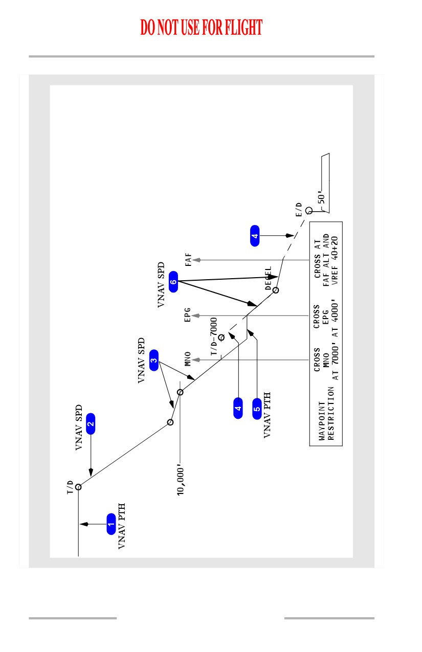
1
Cruise
Before the top of descent, FMC is in cruise mode and uses VNAV PTH and ECON
cruise speed.
2
Descent
After top of descent, FMC is in descent mode and VNAV changes to economy
descent speed and descends in VNAV PTH.
3
Speed Restriction Deceleration
Before the speed restriction altitude, VNAV decelerates to commanded speed
using VNAV PTH.
When at restricted speed, VNAV commands decreased pitch and descends in
VNAV PTH.
4
Altitude Restrictions
The VNAV path conforms to altitude restrictions at MNO, EPG, and the FAF. If
required, VNAV uses a level path until intercepting the idle thrust descent path to
the next altitude constrained waypoint.
[Option - With geometric descent path]
The VNAV path conforms to altitude restrictions at MNO, EPG, and the FAF. The
thrust mode changes to FMC SPD as required to maintain the target speed.
5
Approach
VNAV descends and starts approach in VNAV PTH at the commanded speed.
6
Missed Approach
When TOGA is pushed during approach, or when crossing the missed approach
point, VNAV disengages.
When selected during missed approach, VNAV engages in VNAV SPD.
7
Missed Approach Level Off
At missed approach altitude VNAV changes to VNAV PTH.
VNAV Speed Descent
A speed descent may be selected manually by selecting the SPEED prompt on the
PATH DES page. With no E/D specified, the speed descent is the only descent
mode available.
11.31.28
Flight Management, Navigation -
Flight Management System
Operation
Boeing 737 Operations Manual
The speed descent maintains the target speed. Normally, the target speed is
economy above the airspeed restriction altitude and 240 knots below that altitude,
until deceleration is necessary for the approach. VNAV will not permit descent
below the altitude restriction until the airspeed is at or below the restricted value.
The speed descent normally begins automatically at the calculated T/D, provided
the MCP altitude is reset for the descent. At the T/D, the FMC commands pitch to
maintain target descent speed. LNAV does not have to be engaged in order to fly
a VNAV speed descent.
The descent attempts to comply with waypoint altitude restrictions, and will not
violate these restrictions. The VNAV speed descent will not, however, guarantee
the airplane reaches an altitude restriction at the required point.
A speed descent cannot automatically revert to a path descent, except during
STAR, approach transition, or approach leg with a vertical angle. However, if all
required parameters for a path descent are available, a path descent may be
manually selected at any time by selecting the PATH prompt on the speed descent
page.
11.31.29
Flight Management, Navigation -
Flight Management System
Operation
Boeing 737 Operations Manual
VNAV Cruise and Speed Descent Profile (Nonprecision Approach)
11.31.30
Flight Management, Navigation -
Flight Management System
Operation
Boeing 737 Operations Manual
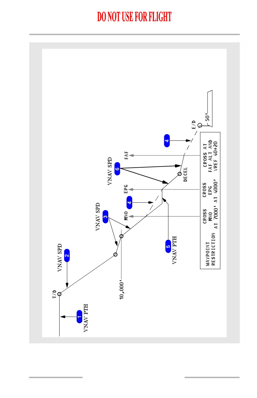
[Option - With geometric descent path]
11.31.31
Flight Management, Navigation -
Flight Management System
Operation
Boeing 737 Operations Manual
1
Cruise
Before the top of descent, FMC is in cruise mode and uses VNAV PTH and ECON
cruise speed.
2
Descent
After top of descent, FMC is in descent mode and VNAV changes to economy
descent speed and descends in VNAV SPD.
3
Speed Restriction Deceleration
Before the speed restriction altitude, VNAV decelerates to commanded speed
using VNAV SPD.
When at restricted speed, VNAV commands decreased pitch and descends in
VNAV SPD.
4
VNAV Path
During a speed descent, VNAV may not maintain the FMC computed VNAV path.
However, if E/D shows, a VNAV path is available.
5
Altitude Restrictions
VNAV conforms to altitude restrictions at MNO and EPG. After MNO VNAV
continues an idle thrust descent using VNAV SPD.
Upon reaching the next altitude restriction, VNAV commands level flight using
VNAV PTH. The thrust mode changes to FMC SPD.
6
Descent and Approach
After EPG, VNAV continues the idle thrust descent using VNAV SPD.
Prior to the approach, VNAV decelerates to approach speed. The FMC prompts
manual flap extension.
11.31.32
Flight Management, Navigation -
Flight Management System
Operation
Boeing 737 Operations Manual
Vertical Angle
A vertical angle can be assigned to a waypoint from the navigation database. This
vertical angle defines a VNAV path between the waypoint and the waypoint
preceeding it. This feature can be available in approaches, approach transitions,
and STARs. For example, the vertical angle for the glidepath of an ILS approach
would typically be 3 degrees. This angle is displayed on the ACT RTE LEGS page
above the speed/altitude line for the associated waypoint. Vertical angles may be
expected in any approach ending at RWXXX or MAXXX. The E/D will be
RWXXX or MAXXX, and the E/D altitude will be either threshold crossing
height (TCH - typically 50 feet above the touchdown zone elevation) or the
altitude specified at MAXXX.
If a path (VNAV PTH) descent is active when a vertical angle leg becomes active,
the path mode will remain active, but VNAV will follow the vertical angle rather
than the idle thrust descent path.
If the vertical angle leg becomes active during a speed descent, the VNAV mode
will change to VNAV PTH automatically, and there will be no SPEED prompt on
the descent page.
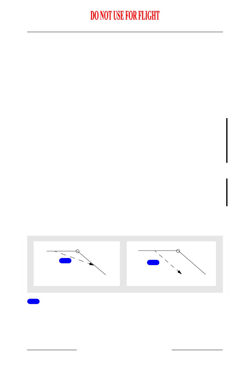
Early Descent
A descent in VNAV started before the top of descent point is an early descent. If
a path descent is planned, VNAV commands a 1000 fpm descent until the idle
descent path is intercepted. If a speed descent is planned, VNAV commands an
idle thrust descent.
To start an early descent, use DES NOW prompt on the DES page.
[Option - With speed and altitude intervention]
An early descent can also be started by pushing the altitude intervention switch.
T/D
T/D
1
2
DES NOW (VNAV PTH)
DES NOW (VNAV SPD)
1
DES NOW (VNAV PTH)
With a VNAV path descent planned, VNAV starts an early descent at 1000 fpm
and captures the idle descent path. VNAV uses FMC SPD for the autothrottle
mode and VNAV PTH for the pitch mode.
11.31.33
Flight Management, Navigation -
Flight Management System
Operation
Boeing 737 Operations Manual
2
DES NOW (VNAV SPD)
With a VNAV speed descent planned, VNAV starts an idle thrust early descent.
VNAV does not attempt to capture the VNAV descent path. VNAV uses VNAV
SPD for the pitch mode and the autothrottle commands IDLE, followed by ARM.
Approach
The FMC transitions to “on approach” when the airplane is within:
•
2 NM of the first approach waypoint (including approach transitions such
as arcs and procedure turns), or
•
2000 feet of airport elevation, whichever occurs first.
When the FMC is “on approach”, the following features are available:
• UNABLE RNP alerting levels are higher
• when preparing for a missed approach and the MCP altitude is set at least
300 feet above the current airplane altitude, VNAV will continue to
command a descent
• if the airplane is more than 200 feet below the vertical path, VNAV
commands zero vertical speed until intercepting the path.
Note: Display of a specified path angle is not limited to approaches. A path angle
may be defined for a leg in a STAR and displays on the RTE LEGS page
for the procedure.
The FMC transitions out of “on approach” under the following conditions:
• selecting TO/GA
• the airplane lands
• the waypoint cycles to the first waypoint of the missed approach
• executing a direct-to waypoint in the missed approach.
The following situations are generally encountered during approach operations,
but are not determined by “on approach” logic:
• If speed intervention is engaged:
• during a path descent with flaps up on an idle leg, VNAV switches to
VNAV SPD
• with flaps down, VNAV remains in VNAV PTH
• when a point to point (geometric path) leg is active, VNAV remains in
VNAV PTH
• while a vertical angle leg (GP x.xx on RTE LEGS page) is active,
VNAV remains in VNAV PTH
• if a vertical angle leg (GP x.xx on RTE LEGS page) becomes active,
VNAV switches to VNAV PTH without pilot action
• if on a vertical angle leg, and cross track exceeds two times the RNP
value, while LNAV is not engaged, VNAV will disengage.
11.31.34
Flight Management, Navigation -
Flight Management System
Operation
Boeing 737 Operations Manual
VNAV will remain engaged at all flap settings, allowing approaches to be flown
using the vertical angle guidance. Speed for final approach can be set on the
APPROACH REF page.
[Option - FMC U10.3 and later]
If an ILS approach is flown in VNAV using vertical angle guidance, VNAV will
disconnect when passing the GS-XXX point if G/S is armed, but it can be
reengaged. If the GS-XXX point is deleted, VNAV will remain engaged
throughout the approach.
For an approach without a runway waypoint on the RTE LEGS page, the VNAV
path is calculated to the MDA or a calculated altitude at the missed approach
point. The calculated altitude may be below the MDA to ensure a flight path angle
and normal threshold crossing height.
Note: It is the flight crew’s responsibility not to descend below the MDA until
adequate visual contact is achieved.
Go-Around
Below 2000 feet radio altitude, a go-around can be initiated by any of the
following methods:
• pushing either TO/GA switch while in a descent
• selecting Go-Around Thrust Limit when below MCP altitude with N1
autothrottle mode engaged
• executing a direct-to waypoint in the missed approach (other than the
missed approach point)
• automatically while in a decent and the last waypoint of the approach
cycles to the first waypoint of the missed approach.
Once the go-around is initiated:
• the thrust limit changes to go-around thrust
• the FMC transitions from active descent to active climb
• all descent altitude constraints below the current airplane altitude are
deleted and replaced with predicted altitudes
• the original destination airport (airport from which the go-around was just
initiated) becomes the new origin airport allowing SID selection if a
diversion to another airport is required.
Note: VNAV and LNAV can only be engaged when the airplane climbs above
400 feet radio altitude, unless the loaded missed approach procedure is
from the navigation database in which case VNAV and LNAV can be
engaged below 400 feet radio altitude.
11.31.35
Flight Management, Navigation -
Flight Management System
Operation
Boeing 737 Operations Manual
If the go-around was initiated by pushing a TO/GA switch or selection of
go-around thrust, the CRZ ALT will change to the highest of:
• the highest constraint in the missed approach
•
1500 feet above airport elevation
• the MCP altitude.
Note: If the MCP altitude is the lowest of the three, the autopilot, if engaged, will
level off at the MCP altitude.
If the go-around was initiated by direct-to or waypoint sequencing, the CRZ ALT
will change to the highest of:
• the highest constraint in the missed approach
•
1500 feet above airport elevation.
If VNAV is engaged to fly the missed approach, the thrust limit changes to climb.
Refer to section NP20.xx, Go-Around Procedure and section 4.20, Go-Around for
additional information.
11.31.36
Flight Management, Navigation -
Flight Management System
Operation
Boeing 737 Operations Manual
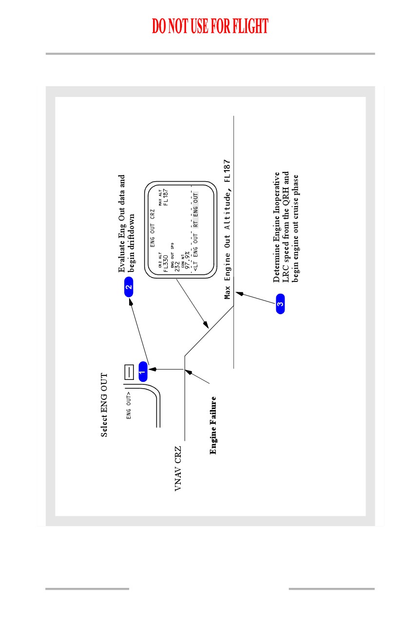
VNAV Cruise (Engine Out Above Eng Out Max Alt)
[Option - FMC U10.3 and later]
11.31.37
Flight Management, Navigation -
Flight Management System
Operation
Boeing 737 Operations Manual
1
Engine Out Modification
Select the ENG OUT prompt on the CRZ page. The ENG OUT page displays the
appropriate engine out driftdown performance data to enable the airplane to
descend to the engine out maximum altitude. Refer to FMC Cruise, section 11.42
for a complete description of the ENG OUT CRZ page.
2
Drift Down Execution
After selecting the left or right ENG OUT mode, perform the driftdown as
follows:
• disconnect A/T
• set maximum continuous thrust on operating engine (N1 line)
[Option - FMC U10.3 and later]
• set MCP speed to ENG OUT SPD
• set MCP altitude to MAX ALT or lower altitude as required
• select LVL CHG.
The airplane then descends at CON thrust and the driftdown airspeed to the MAX
ALT. As the driftdown proceeds and airplane gross weight decreases, the
maximum altitude may increase.
Note: The engine out cruise page provides advisory performance data for
operating with one engine.
3
Engine Out Cruise
Engine out cruise operates like normal cruise with engine out cruise speeds. If
range is a factor, determine Engine Inoperative LRC speed from the QRH. Thrust
limit remains in CON.
Required Time of Arrival (RTA)
VNAV controls cruise speed to achieve a flight crew specified arrival time at a
specified waypoint. After the appropriate waypoint and RTA are input to the FMC,
the FMC will compute a recommended takeoff time, speeds required to comply
with the RTA, and progress information for the flight. If the RTA is not achievable,
the RTA UNACHIEVABLE scratchpad message is displayed.
Data Entry Rules
Altitude Entry
Altitudes can be entered into the FMC as three digit (xxx), four digit (xxxx), five
digit (xxxxx), or flight level (FLxxx) numbers. The FMC automatically displays
altitude or flight level entries in the proper form based on the transition altitude.
Some data lines further restrict the valid entry forms.
11.31.38
Flight Management, Navigation -
Flight Management System
Operation
Boeing 737 Operations Manual
Three digit entries represent altitude or flight levels in increments of 100 feet.
Leading zeros are required.
Examples of three digit (xxx, FLxxx) entries with transition altitude = 10,000 feet:
•
800 feet is entered as 008 or FL008 and displayed as 800
•
1,500 feet is entered as 015 or FL015 and displayed as 1500
•
11,500 feet is entered as 115 or FL115 and displayed as FL115
•
25,000 feet is entered as 250 or FL250 and displayed as FL250.
Four digit entries represent feet, rounded to the nearest ten feet. Leading zeros are
required. This form is used when the altitude does not exceed 9,994 feet.
Examples of four digit (xxxx) entries with transition altitude = 18,000 feet:
•
50 feet is entered as 0050 and displayed as 50
•
835 feet is entered as 0835 and displayed as 840
•
1,500 feet is entered as 1500 and displayed as 1500
•
8,500 feet is entered as 8500 and displayed as 8500
•
9,994 feet is entered as 9994 and displayed as 9990.
Five digit entries represent feet, rounded to the nearest ten feet. This form is used
when the altitude exceeds 9,994 feet.
Examples of five (xxxxx) digit entries with transition altitude = 4,000 feet:
•
50 feet is entered as 00050 and displayed as 50
•
835 feet is entered as 00835 and displayed as 840
•
1,500 feet is entered as 01500 and displayed as 1500
•
8,500 feet is entered as 08500 and displayed as FL085
•
9,995 feet is entered as 09995 and displayed as FL100
•
11,500 feet is entered as 11500 and displayed as FL115
•
25,000 feet is entered as 25000 and displayed as FL250.
Negative altitude entries are allowed to -1000 feet.
Airspeed Entry
Airspeeds can be entered into the FMC as calibrated airspeed or Mach number.
Calibrated airspeeds are entered as three digits (xxx) in knots. Mach numbers are
entered as one, two, or three digits following a decimal point.
11.31.39
Flight Management, Navigation -
Flight Management System
Operation
Boeing 737 Operations Manual
Data Pairs
Many CDU pages display data in pairs separated by a slash “/.” Examples of these
pairs include wind direction/speed and waypoint airspeed/altitude restrictions.
When entering both values in a pair, the slash is inserted between the values. When
it is possible to enter only one value of the pair, the slash may not be required.
When entering only the outboard value of a pair, the trailing or leading slash may
be entered, but is not required before transferring to the data line. When entering
the inboard value of a pair, the trailing or leading slash must be entered before
transferring to the data line. Omission of the required slash normally results in an
INVALID ENTRY message.
Bearing Entry
Entry of a bearing value requires three digits. For example, key 090, not 90. A
bearing entry of 360 is displayed as 000.
Plus/Minus Signs
When entering temperature or an along-track displacement distance, positive
values are assumed by the FMC and + signs are not required. For negative values,
key in the - sign.
11.31.40
Boeing 737 Operations Manual
Flight Management, Navigation
Chapter 11
Flight Management Computer
Section 32
FMC Databases
The FMC contains two databases:
• performance database
• navigation database.
The performance database eliminates the need for the flight crew to refer to a
performance manual during flight, and provides the FMC with the information
required to calculate pitch and thrust commands. All information normally
required can be displayed on the CDU. The database includes:
• airplane drag and engine characteristics
• maximum and optimum altitudes
• maximum and minimum speeds.
Maintenance personnel can refine the database by entering correction factors for
drag and fuel flow.
The navigation database includes most information normally determined by
referring to navigation charts. This information can be displayed on the CDU or
navigation display. The database contains:
• the location of VHF navigation aids
• waypoints
• airports
• runways
• other airline selected information, such as SIDs, STARs, approaches, and
company routes.
If the permanent database does not contain all of the required flight plan data,
additional airports, navaids, and waypoints can be defined by the crew and stored
in either a supplemental or a temporary navigation database. Use of these
additional databases provides world-wide navigational capability, with the crew
manually entering desired data into the FMC via various CDU pages. Information
in the supplemental navigation database is stored indefinitely, requiring specific
crew action for erasure; the temporary navigation database is automatically erased
at flight completion.
The supplemental and temporary databases share storage capacity for forty
navaids and six airports, the entries being stored in either database on a first come,
first served basis. For the waypoint category, exclusive storage is reserved in the
temporary database for twenty entries (including those created on the RTE or RTE
LEGS pages). An additional twenty waypoints (up to a maximum of forty) can be
stored in either the temporary or supplemental database on a first come, first
served basis.
11.32.1
Flight Management, Navigation -
Flight Management Computer
Boeing 737 Operations Manual
When any storage capacity is full, entries which are no longer required should be
deleted by the crew to make space for additional new entries. Created waypoints
cannot be stored in the database runway category.
The FMC contains two sets of navigation data, each valid for 28 days. Each set
corresponds to the normal navigation chart revision cycle. The FMC uses the
active set for navigation calculations. The contents of the navigation database are
periodically updated and are transferred to the FMC before the expiration date of
the current data.
Thrust Management
The autothrottle operates in response to flight crew mode control panel inputs or
to automatic FMC commands. Reference thrust can be selected on the N1 LIMIT
page. Automatic FMC autothrottle commands are made while VNAV is engaged.
The autothrottle system:
• uses reference thrust limits calculated by the FMC
• commands the thrust levers
• commands thrust equalization through the electronic engine controls.
Thrust limits are expressed as N1 limits. Thrust equalization references N1.
The FMC calculates a reference thrust for the following modes:
• takeoff
• reduced climb
• derated takeoff
• cruise
• assumed temperature takeoff
• continuous
• climb
• go-around.
[Option - With takeoff bump thrust]
The FMC calculates a reference thrust for the following modes:
• takeoff
• reduced climb
• derated takeoff
• cruise
• assumed temperature takeoff
• continuous
• takeoff bump
• go-around.
• climb
[Option -With takeoff bump thrust and quiet climb]
The FMC calculates a reference thrust for the following modes:
• takeoff
• reduced climb
• derated takeoff
• cruise
• assumed temperature takeoff
• continuous
• takeoff bump
• go-around
• climb
• noise abatement (cutback).
11.32.2
October 15, 2001
Flight Management, Navigation -
Flight Management Computer
Boeing 737 Operations Manual
The thrust reference mode automatically transitions for the respective phase of
flight. These modes can be selected on the N1 LIMIT page. The selected thrust
reference mode is displayed on the thrust mode display.
[Option - FMC U10.1 and later, with automatic thrust reduction after takeoff]
The flight crew can specify the thrust reduction height where the transition from
takeoff to climb thrust takes place by making an entry on TAKEOFF REF page 2.
Allowable entries are 800 feet to 15,000 feet.
[Option - FMC U10.3 and later]
The default value is determined by the airline and is stored in the model/engine
database.
[Option - With quiet climb]
With cutback mode selected ON, the flight crew can specify the thrust reduction
and restore altitudes on TAKEOFF REF page 2. The FMC calculates and
commands a cutback thrust rating based on data provided through the
model/engine database. In addition the FMC uses the reduction altitude to
calculate the required cutback altitude. A new N1 is calculated during climb and
normal climb thrust is restored at the RESTORE altitude.
Reduced Thrust Takeoff
Reduced thrust takeoffs lower EGT and extend engine life. They are used
whenever performance limits and noise abatement procedures permit.
Takeoff Derate
[Option - FMC U10.1 and later]
Fixed derates can be selected on the N1 LIMIT page. Performance data for these
derates is provided in the Airplane Flight Manual (AFM).
With derated takeoff selected, the thrust setting parameter is considered a
limitation for takeoff; therefore, thrust levers should not be advanced further
except in an emergency. A further thrust increase following an engine failure
could result in a loss of directional control while on the ground. Use the takeoff
speeds supplied by the FMC or specified in Chapter PI, Performance-Inflight, for
the selected derate condition.
Derated takeoff rating can be further reduced by assumed temperature.
[Option - With FMC computed QRH takeoff speeds]
Use the takeoff speeds provided by the FMC or specified in Chapter PI,
Performance-Inflight, for the selected derate or variable takeoff rating condition.
Use the takeoff speeds specified in Chapter PI, Performance-Inflight, for the
selected derate or variable takeoff rating condition.
11.32.3
Flight Management, Navigation -
Flight Management Computer
Boeing 737 Operations Manual
Assumed Temperature Thrust Reduction Takeoff
[Option - FMC U10.1 and later]
A takeoff thrust less than the full rated thrust may be achieved by using an
assumed temperature that is higher than the actual temperature. The desired thrust
level is obtained through entry of a SEL TEMP value on the N1 LIMIT page or
TAKEOFF REF page 2. Use approved sources for selecting the assumed
temperature.
The maximum thrust reduction authorized is 25 percent below any certified rating.
Do not use assumed temperature reduced thrust if conditions exist that affect
braking, such as slush, snow, or ice on the runway, or if potential windshear
conditions exist.
If the assumed temperature method is applied to a fixed derate, application of
additional power should not exceed the fixed derate N1 limit as loss of directional
control could occur while on the ground.
When the assumed temperature method is used with full rate, the reduced thrust
setting is not considered a limitation. If conditions are encountered where
additional thrust is desired, the crew can manually apply full thrust.
Takeoff Bump Thrust
[Option]
Takeoff bump thrust may be used to meet extra thrust requirements for takeoff at
certain airports. Takeoff bump thrust provides thrust above normal maximum
takeoff thrust. The takeoff thrust bump setting may be selected on the N1 LIMIT
page. Takeoff thrust bump is only available for takeoff, and cannot be applied to
go around, max continuous, or climb thrust ratings. If takeoff thrust bump is
selected, assumed temperature reduced thrust is not available.
Derated Thrust Climb
Two fixed climb thrust derates can be selected on the N1 LIMIT page. CLB-1
provides a climb limit reduced by 3% N1 (approximately 10% thrust). CLB-2
provides a climb limit reduced by 6% N1 (approximately 20% thrust). The
reduced climb setting gradually increases to full rated climb thrust by 15,000 feet.
In cruise, the thrust reference automatically changes to CRZ. The reference can be
manually selected on the N1 LIMIT page.
Use of an assumed temperature reduced thrust takeoff or takeoff derate affects the
FMCs climb derate computation. If a reduced thrust takeoff has been specified on
the TAKEOFF REF page, the FMC will re-compute CLB-1 and CLB-2 values as
required to avoid a climb N1 value greater than the reduced thrust takeoff N1
value.
Use of derated climb thrust reduces engine maintenance costs, but increases total
trip fuel.
11.32.4
Flight Management, Navigation -
Flight Management Computer
Boeing 737 Operations Manual
Fuel Monitoring
The FMC receives fuel data from the fuel quantity indicating system. Fuel
quantity values show on the PERF INIT page and on PROGRESS page 1/3.
The scratchpad message VERIFY GW AND FUEL shows if total fuel quantity
data is invalid. The PERF INIT page FUEL line changes to dashes. The FMC uses
the last valid fuel quantity for performance predictions and VNAV operation. The
flight crew should manually enter estimated fuel weight. Periodic fuel weight
update is required for the remainder of the flight to keep gross weight current. The
FMC does not update the manual fuel weight entry. The scratchpad message
VERIFY GW AND FUEL shows again each 30 minutes if subsequent entries are
not performed. The scratchpad message does not show during descent with Vref
selected.
The scratchpad message CHECK FMC FUEL QUANTITY shows if the FMC has
detected an unexpected drop in fuel quantity.
The FMC continually estimates the amount of fuel that will remain when the
destination airport is reached if the active route is flown. The CDU message
USING RSV FUEL is displayed if the estimate is less than the fuel reserve value
entered on the PERF INIT page. The CDU message INSUFFICIENT FUEL is
displayed if predicted fuel at destination will be 2000 lb (900 kg) or less.
Loss of FMC Electrical Power
The FMC requires continuous electrical power to operate. When the electrical
power is interrupted for less than ten seconds:
• LNAV and VNAV disengage
• all entered data is retained by the FMC
• the FMC resumes normal operation when power is restored.
If power is lost for ten seconds or more on the ground, all preflight procedures and
entries must be done again when power is restored.
If power is lost for more than ten seconds in flight:
• LNAV and VNAV disengage
• all entered data is retained by the FMC, and when power is restored the
RTE LEGS page is displayed with the scratchpad message
SELECT ACTIVE WPT/LEG.
Before LNAV can engage, the FMC must be instructed how to return to the route.
Select the desired active waypoint and proceed direct or intercept a course to the
waypoint.
11.32.5
Flight Management, Navigation -
Flight Management Computer
Boeing 737 Operations Manual
FMC Failure
[Option - Dual FMC]
Single FMC Failure
The FMC/CDU is designed to automatically preserve the most capable modes of
navigation and guidance that can be maintained with the equipment and
navigation aids available. If an error or system failure results in reduced capability,
then the FMC may generate a crew message for display in the CDU scratchpad. If
other system inputs to the FMC should fail, affected CDU displays are blanked to
prevent the display of misleading or erroneous data. For example, loss of the total
fuel input causes some performance related data to be blank. The messages and
FMC internal responses provide an orderly transition from full FMC guided flight
to less automated capability.
If the right FMC fails, the FMC alert light and the FMC message light will
illuminate. The message SINGLE FMC OPERATION will be displayed in both
scratchpads. VTK will display on the right navigation display. LNAV and VNAV
will disengage if autopilot B is in use (can be reengaged if autopilot A is selected).
After
25 to
30 seconds, the right navigation display will display failure
information. The right navigation display may be restored by placing the FMC
source select switch to BOTH ON L.
Note: If the above indications are observed with no VTK on the right navigation
display, there is a disagreement between left and right FMC data. Moving
the FMC Source Select Switch to BOTH ON L should allow the two FMCs
to resynchronize. The switch may then be returned to NORMAL when the
message DUAL FMC OP RESTORED is displayed on both scratch pads.
[Option - MCDU]
If the left FMC fails, the FMC alert light will illuminate. The MENU page will
appear on both CDUs. VTK will appear on the left navigation display. LNAV and
VNAV will disengage, but can be reengaged if autopilot B is in use or is selected.
After 25 to 30 seconds, the left navigation display will display failure information.
To restore full operation, the FMC source select switch must be moved to BOTH
ON R.
[Option - FMC U10.2 and later]
Note: During an FMC software restart, the navigation display map track may
rapidly slew to 0 degrees then to the correct value.
11.32.6
Flight Management, Navigation -
Flight Management Computer
Boeing 737 Operations Manual
Dual FMC Failure
[Option - MCDU]
If both FMCs fail, the FMC alert light will illuminate. The MENU page will
appear on both CDUs. VTK will appear on both navigation displays. LNAV and
VNAV will disengage. After 25 to 30 seconds, both navigation displays will
display failure information.
FMC Failure
[Option - Single FMC]
[Option - CDU]
If the FMC fails, the FMC alert light will illuminate. The FMC/CDU FAIL light
will appear on both CDUs, and both CDUs will display failure modes. VTK will
appear on both navigation displays. LNAV and VNAV will disengage. After 25 to
30 seconds, both navigation displays will display failure information.
[Option - MCDU]
If the FMC fails, the FMC alert light will illuminate. The MENU page will appear
on both CDUs. VTK will appear on both navigation displays. LNAV and VNAV
will disengage. After 25 to 30 seconds, both navigation displays will display
failure information.
[Option - FMC U10.2 and later]
Note: During an FMC software restart, the navigation display map track may
rapidly slew to 0 degrees then to the correct value.
11.32.7