PGEV and PGE Locomotive Governors. Manual - part 11
 

  Index      Locomotives - books     PGEV and PGE Locomotive Governors - manual 1990


Search            


Content   ..  9  10  11  12   ..


PGEV and PGE Locomotive Governors. Manual - part 11


Manual 36703 

PGEV and PGE Locomotive Governors 


Woodward 

33 


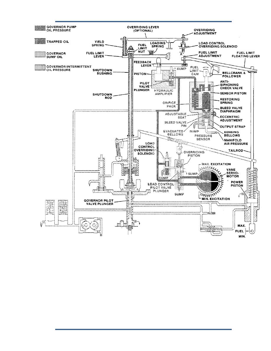
Figure 3-6a. Schematic Diagram, Fuel Limiter and Linkage 


When these opposing forces balance, the bleed-valve diaphragm floats just off of 
its seat bypassing oil to sump. This rate of oil flow maintains a constant volume 
of oil in the area under the sensor piston. 
 
Assume that the governor speed setting is advanced to a higher speed setting 
and a higher manifold-air pressure. The governor power piston moves upward 
supplying the additional fuel required for engine acceleration. Since manifold air 
pressure lags engine acceleration, the fuel-limiter cam and bellcrank initially 
remain stationary until manifold air pressure rises. 

PGEV and PGE Locomotive Governors 

Manual 36703 


34 

Woodward 

As the governor power piston moves upward increasing fuel, the fuel-limit floating 
lever pivots about the upper leg of the bellcrank and depresses the right end of 
the feedback lever on the hydraulic amplifier. This pushes the amplifier pilot-
valve plunger below center, allowing pressured oil to flow into the area under the 
amplifier piston, causing the piston to rise. As the piston rises, it simultaneously 
lifts the left ends of both the fuel-limiter lever and the feedback lever. 
 
When the fuel limit lever contacts the fuel-limit nut on the shutdown bushing, it 
begins lifting the shutdown rod to re-center the governor pilot-valve plunger. The 
upward movements of the fuel-limit and feedback levers continue until the left 
end of the feedback lever raises far enough to re-center the amplifier-pilot-valve 
plunger and stop the flow of oil to the amplifier piston. At this point, the fuel-limit 
lever re-centers the governor pilot-valve plunger, stopping the upward movement 
of the governor power piston. This limits the amount of fuel to provide a proper 
fuel/air ratio for efficient burning. Although the governor flyweights are in an 
underspeed condition at this time, the power piston remains stationary until 
manifold air pressure rises. 
 
As engine speed and load increase, manifold air pressure rises after a short time 
lag. The increase in manifold air pressure produces a proportionate increase in 
the sensing-bellows force. The bellows force, now greater than the restoring-
spring force, causes the bleed-valve diaphragm to move further off its seat. This 
allows a greater flow of oil to sump than is admitted through the orifice pack. 
Governor oil pressure acting on the upper side of the sensor piston forces the 
piston (and cam) downward and, in the process, further compresses the restoring 
spring. The piston continues its downward movement until the net increase in 
restoring-spring force equals the net increase in bellows force. This restores the 
bellows and bleed-valve diaphragm to their original positions. At this point, the 
outflow of oil is again equal to the inflow, and the piston stops moving. 
 
As the sensor piston and cam move downward in response to a rise in manifold 
air pressure, the bellcrank rotates in a cw direction. This allows the floating-lever 
pivot point, the left end of the lever, and in turn the hydraulic-amplifier pilot-valve 
plunger to rise. 
 
The loading spring under the pilot-valve plunger maintains a positive contact 
between the plunger, levers, bellcrank, and cam. When the pilot-valve plunger 
rises above center, the oil under the amplifier piston bleeds to sump through a 
drilled passage in the center of the plunger. The passage in the plunger restricts 
the rate of oil flow to sump and decreases the rate of movement of the amplifier 
piston to minimize hunting. As the amplifier piston moves downward, the left end 
of the fuel-limit lever also moves downward. This lowers the shutdown rod which 
in turn lowers the governor pilot-valve plunger and increases engine fuel. 
 
The above events occur in continuous and rapid sequence. Normal governor 
operation is overridden during an acceleration transient and engine fuel is 
scheduled as a function of manifold air pressure, regardless of governor speed 
setting. To prevent interference with normal governing action during steady-state 
operation, the sensor piston and cam continue their downward movement until 
sufficiently below the effective limiting point. 

Manual 36703 

PGEV and PGE Locomotive Governors 


Woodward 

35 

Conversely, a drop in manifold air pressure rotates the bellcrank ccw. This lowers 
the fuel-limit lever, depressing the pilot-valve plunger, and releases pressured oil 
to the underside of the amplifier piston. The shutdown rod and governor pilot-
valve plunger are raised, releasing oil from the power-piston cylinder to sump, 
and decreasing fuel to the engine. The left end of the fuel-limit floating lever 
pivots upwards releasing the hydraulic amplifier pilot-valve plunger upward. As 
the control land of the pilot-valve plunger opens the port from the piston cylinder, 
oil is bled to sump through a hole in the pilot-valve-plunger shaft. The shutdown 
rod is lowered, allowing the governor pilot-valve plunger to re-center. 


Load Control Override Linkage 

 
The load-control-override linkage (Figure 3-6a) consists of an overriding lever 
which connects the left end of the fuel-limit lever to the load-control-overriding 
solenoid through a pin-and-yield spring combination. The overriding solenoid 
adjustment set screw must be adjusted to fully depress the overriding-solenoid 
plunger completely, at a point just before the fuel-limit lever contacts the fuel limit 
nut. Pressured oil is released to the underside of the overriding piston, lifting the 
load-control pilot-valve plunger in the decrease-load direction. During 
acceleration transients, when fuel limiting occurs, the integral-vane servomotor 
begins to unload prior to an acceleration lag, reducing overload and poor 
acceleration. Depending on engine and turbo supercharger characteristics, 
premature unloading can permit the engine to accelerate quickly and raise the 
manifold air pressure rapidly enough to prevent any fuel limiting from taking 
place. 


On this governor application, load on the engine is adjusted through 
a servomotor-operated rheostat in the field excitation circuit of a 
generator. The servomotor, in turn, is controlled through the 
governor's load-control system. 

 
As engine speed nears the new setting, and manifold air pressure rises, a 
downward movement of the fuel-limit lever permits the overriding-solenoid 
plunger to rise. Oil is released from under the load-control-overriding piston to 
sump, lowering the load-control pilot-valve plunger. The load-control pilot-valve 
plunger moves down, releasing pressured oil to the vane servomotor, and 
increases excitation. This increases load in proportion to the increase in engine 
speed. 


LVDT Load Control System 

 
The secondary purpose of the governor is to maintain a definite horsepower 
output of the engine for a specific speed setting of the governor. To achieve this 
objective, the LVDT (Linear Variable Differential Transformer), adjusts (through 
external circuitry) the generator field excitation current to keep the traction motor 
load at a set point. 

PGEV and PGE Locomotive Governors 

Manual 36703 


36 

Woodward 

The LVDT provides a linear output voltage over a displacement measuring range 
of 1.000 inch (25.40 mm). It consists of a primary coil and two separate 
secondary windings of enameled copper wire wound on a common cylindrical, 
resin bonded, glass fiber core. A ferromagnetic stainless-steel case houses the 
coil assembly and provides full electromagnetic and electrostatic shielding. All 
internal voids are filled with epoxy resin. The spring-loaded captive core is 
manufactured from nickel iron alloy and moves freely in its guides. The device 
requires an excitation of 6 Vac (RMS) at 2.5 KHz. The device has a resolution of 
25 mV per 0.001 inch (0.03 mm) displacement. 
 
The excitation voltage is applied to the primary winding. The two secondary 
windings are wound in opposite directions to each other. When the movable core 
is centered, the secondary voltages are equal in amplitude, but opposite in 
phase. At other core positions the secondary voltages will still be opposite in 
phase but no longer equal in amplitude. The amount of amplitude difference is 
proportional to the distance of the core from center. 
 
A rectifier assembly connected to the secondary windings of the LVDT converts 
the secondaries' ac voltages to a dc voltage. The amplitude of the dc voltage is 
proportional to core distance from center and the polarity of the dc indicates the 
core direction from center. The rectified dc voltage has a resolution of 10 mV per 
inch (0.39 mV/mm). 
 
The LVDT core center position depends on the governor speed setting. The core 
is positioned by a plunger which senses engine load and governor speed setting. 
A change in engine load (horsepower) moves the core from center position. 
When the engine load increases, the LVDT core moves to cause a decrease in 
generator excitation voltage to decrease load. Since the load is reduced, the 
governor decreases fuel and, at the same time, the LVDT core position. This 
continues until the engine speed is that called for by the governor speed setting 
and the LVDT core is once again centered. 
 
The horsepower is now at the designed value for the present speed setting. The 
governor has 
responded to an increase in load without a long term change in speed. When 
engine load decreases the response is similar, but in opposite directions. 


Start Fuel Limiter 

 
The Starting Fuel Limiter minimizes the tendency of engines to flood when 
starting and minimizes excessive smoking during engine cranking. The starting 
fuel-limiter linkage consists of a fuel limit lever, an adjustable limit screw, and a 
lever spring. Figure 3-6b shows the limiter linkage arrangement. 
 
The limit lever extends over the floating lever between the speed-setting servo 
piston and the power piston tailrod. The tailrod is positioned as a function of the 
fuel setting. The speed-setting servo piston is positioned as a function of speed 
setting. When the tailrod moves up (as fuel increases) sufficiently far, the floating 
lever lifts the free end of the fuel limit lever. The lever spring continually urges the 
limit lever down in the direction to contact the floating lever. 
 
The adjustable limit screw attaches to a lug in the fuel-limit lever. The head of the 
limit screw fits under the shutdown nuts. The limit screw is adjusted so that the 
shutdown nuts (and shutdown rod) are lifted as the tailrod reaches the point 
corresponding to the desired maximum starting fuel. Lifting the shutdown nuts 
and shutdown rod prevents the governor from increasing fuel further. 


Content   ..  9  10  11  12   ..