Power Cab System Reference. Manual - part 6
 

  Index      Locomotives - books     Power Cab System Reference - service manual


Search            


Content   ..  4  5  6  7   ..


Power Cab System Reference. Manual - part 6


22

Power Cab

TM

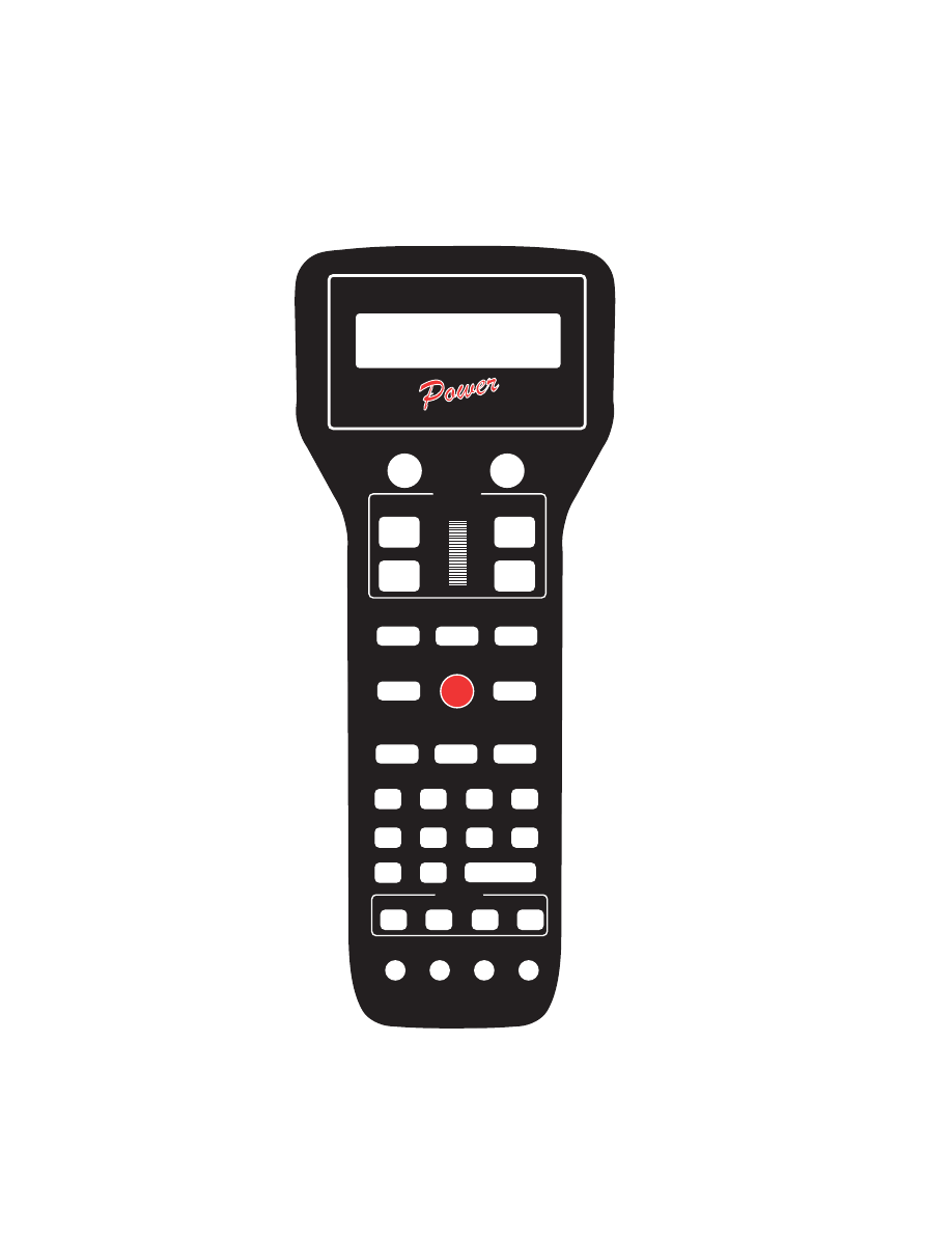
 BUTTON NUMBERING SCHEME

DCC COMPATIBLE COMMAND CONTROL

1

2

3

4

5

6

7

8

9

LOC:1234

FWD: 000

12:00AM

L1-3---

10

11

12

13

14

15

16

17

18

19

20

21

22

23

24

25

26

27

28

29

30

31

32

9

NCE

CAB

23

TABLE OF FACTORY DEFAULT VALUES
FOR “SHIFTED” KEYS

Key # Value ..... Description

Key # Value ... Description

1 ...... 67 ........ Direction

17 .... 96 ...... Assign Loco -> Cab

2 ...... 94 ........ Brake

18 .... 98 ...... Set Clock

3 ...... 90 ........ Increment 4/10 steps

19 .... 99 ...... Use Program Track

4 ...... 74 ........ Increment 1 Step

20 ... 100 ..... Setup Command Station

5 ...... 91 ........ Decrement 4/10 steps

21 ... 101 ..... Setup Cab Parameters

6 ...... 75 ........ Decrement 1 Step

22 ... 118 ..... Reserved

7 ..... 123 ....... reserved

23 ... 102 ..... Setup Macros

8 ...... 81 ........ Headlight

24 ... 108 ..... Reserved

9 ..... 122 ....... reserved

25 ... 119 ..... Reserved

10 .... 125 ....... reserved

26 ... 103 ..... Setup Old Consist

11 .... 116 ....... reserved

27 ... 108 ..... Reserved

12 .... 109 ....... reserved

28 ... 120 ..... Reserved

13 .... 121 ....... reserved

29 ... 115 ..... Reserved

14 .... 117 ....... reserved

30 ... 112 ..... Function 10

15 .... 111 ....... Momentum

31 ... 113 ..... Function 11

16 ..... 97 ........ Program on Main

32 ... 114 ..... Function 12

6 WIRE CAB BUS CABLE WITH RJ-12 CONNECTORS

Pin #

Color

Description

Pin 1 ...... White .............. Power to track
Pin 2 ...... Black .............. Ground
Pin 3 ...... Red ................ - RS-485
Pin 4 ...... Green ............ + RS-485
Pin 5 ...... Yellow ............ +12 volts
Pin 6 ...... Blue ................ Power to track

White

Black

Red

Green

Yellow

Blue

Cab bus cable

Pin 1

Pin 1

General RJ type cable connection

24

4 WIRE CAB BUS CABLE WITH RJ-12 CONNECTORS

**To prevent potential damage, ALWAYS use 4 wire cables when your Power
Cab is used as a Pro Cab. This keeps Power Cab track power from interferring
with the NCE cab bus.

Pin #

Color

Description

Pin 1 ...... White .............. Unused
Pin 2 ...... Black .............. Ground
Pin 3 ...... Red ................ - RS-485
Pin 4 ...... Green ............ + RS-485
Pin 5 ...... Yellow ............ +12 volts
Pin 6 ...... Blue ................ Unused

NOTE: Pro Cab mode cables only need the center four wires for proper operation.

Black

Red

Green

Yellow

Cab bus cable

Pin 1

Pin 1

General RJ type cable connection

Power Cab

TM

 Specifications:

Power Input Requirements: 10-15V regulated DC, 3A maximum
Power Connector: 5.5mm x 2.5mm center positive
Track Power Output: Voltage input minus (-) .5 Volt 2 Amps peak
Cabs: 2 maximum plus USB Interface and/or Mini Panel
Number of simultaneous trains: 12
Number of consists: 16 advanced consists of unlimited number of
locomotives each. Plus 4 old style consists up to 2 locos each.
Range of locomotive addresses: 0-9999
Range of consist addresses: 112-127
Range of accessory addresses: 1-2044
Range of signal addresses: 1-2044
Computer interface: USB optional

Pro Cab

TM

 Mode Specifications:

When the Power Cab is used as a Pro Cab, the following specifications
apply.
Size: 8-3/4 x 3-5/8” x 1”
Power Requirements: 8 VDC 40mA (backlight off) 8 VDC 120mA
(backlight on)
Replacement Encoder: Bournes or Digikey part #3315C-1-006
Speed control: Thumbwheel operated digital encoder with adjustable
ballistic tracking rate. Pushbutton speed control with adjustable auto-repeat
rate (4 pulses per second to one pulse per 4 seconds).
Backlit LCD Display: 2 line by 16 characters/line. Two extra display lines
available for display of additional information when used with computer
dispatcher programs.

25

OPERATING PROCEDURES

THE “NORMAL” DISPLAY

LOC:1234  2:00PM

FWD:108  L1-3---

TOP ROW OF DISPLAY

LOC: Indicates that a locomotive is being operated.
CON: Indicates that a consist is being operated.
2:00PM: Scale Time in either 12 hour or 24 hour format.

BOTTOM ROW OF DISPLAY

FWD: or REV: Indicates the current direction of loco or consist
108 - Indicates the speed step to which the active loco/consist is presently set.
L123456 or - - - - - - -
Indicates which function outputs are ON. Those outputs that are OFF are displayed
as dashes (-). The example above indicates that the Headlight, Function #1 and
Function #3 are on.
Other status information may temporarily be displayed is this area.

SELECTING A LOCOMOTIVE OR

CONSIST

First a word about locomotive addresses. A decoder can have 2 different addresses,
the Short Address (values from 1-127) and the Long Address (sometimes called 4
digit with a range of 0000-9999). A decoder can use one or the other but not both at
the same time. Some entry level decoders can only use the Short Address.

As you can see above there is an overlap in the address ranges between the short
and long address. You can have a Long Address of 6 and a Short Address of 6.
They are not the same. To use a short address (range 1-127) it is selected on the
cab by entering only the significant digits (no zeros before you get to the numbers).
To enter a long address in the range of 0-127 put a zero before the digits. A long
address between 0 and 127 will have an asterisk (*) before the loco address on the
cab display as below:

LOC:*006 2:00PM

LOC:*006 2:00PM

LOC:*006 2:00PM

LOC:*006 2:00PM

LOC:*006 2:00PM

ENTER LOCO:   _

ENTER LOCO:   _

ENTER LOCO:   _

ENTER LOCO:   _

ENTER LOCO:   _

NOTE: You will notice that the short address 0 is not available but the long address 0
is listed as a valid address. Short address 0 is the “broadcast” address for DCC. If
you were to send commands to short address 0 all locomotives on the layout would
respond causing chaos. For this reason we don’t allow use of short address 0. Long
address 0 can be used just like any other locomotive address.

Loco or consist
currently being
controlled

Speed step
and direction
of current
loco

Current time
from system
fast clock or
display of
track current

Status of locomotive
decoder functions


Content   ..  4  5  6  7   ..