Power Cab System Reference. Manual - part 3
 

  Index      Locomotives - books     Power Cab System Reference - service manual


Search            


Content   ..  1  2  3  4  ..


Power Cab System Reference. Manual - part 3


10

INSTALLING HARD WIRED DECODERS

Locomotive decoders come as convenient plug-in models (usually designed for one
specific loco or family of locomotives) or as lower cost “hard wired” types that can be
wired directly to many different locomotives. Below is a description of a typical hard
wired installation.

Read the following section on decoders before starting. There are shortcuts to
temporary installations of the other components, but do not shortcut the decoder. We
recommend you get your first decoder installed by a dealer or locomotive
manufacturer just so you have a good example of how it’s done.

The most important part of a successful decoder installation is proper isolation of
both motor brushes from the track so that they are driven only by the decoder.
Failure to isolate will definitely damage the decoder. Damage caused by failure to
isolate the motor is not covered by the guarantee or warranty.

We find it preferable to mount the decoder with 1/2" wide 3M photo-mount double
sided foam tape (we get ours at the local supermarket).

Before test running your newly converted locomotive on full power double check
your wiring to make sure the motor is fully isolated and that there are no pinched or
broken wires. We see many decoders returned due to wires getting pinched between
the body shell and frame causing shorts.

Due to the high in-rush current of incandescent grain-of-wheat type bulbs (about 10
times the normal operating current) we have rated the decoder function outputs at
100mA each. We recommend Miniatronics part number 18-014-10 (2.4mm diameter
14 volt/30mA) bulbs for good results. If you are running higher voltages you will need
to use 16 or 18 volt bulbs.

Note 1: The function common (blue wire) is the positive lead providing rectified DC voltage. If you
elect to NOT use the common, power the light or other device from either track power pickup for
“half-wave” operation (approx. 1/2 voltage).

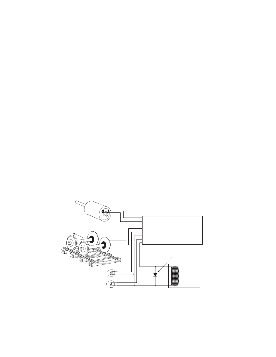
Relay, Smoke

unit, etc.

-

+

Note: If a function controlled device presents
inductive load (such as a relay), always use
a suppression diode (such as 1N4004 or 1N914)
across the device.

Motor -

Motor +

Right Track Power Pickup

Left Track Power Pickup

Forward Light

Light or Function Common (see note 1)

Reverse Light

Function 1 (not on all decoders)

Gray

Orange

Red

Black

White

Blue

Yellow

Green

Blue

Left Rail
Fireman’s Side

Right Rail
Engineer’s Side

Motor

WARNING: To prevent decoder damage,
ALWAYS make sure the motor brushes are
properly isolated before applying power.

Forward

11

If you need to use higher current lamps (50-150mA) we recommend a 22 ohm 1/4
Watt resistor in series with each bulb (this will also greatly extend bulb life). The
function outputs are rated at 150mA continuous if used with LEDs or other low in-
rush devices.
Always make sure the motor is isolated from the frame. Always make sure
metal couplers are isolated from the frame.

PRECAUTIONARY NOTES FOR DECODERS

MAKE SURE NO METAL PART OF THE LOCOMOTIVE TOUCHES ANY METAL

PART OF THE DECODER. APPLY ELECTRICAL TAPE TO THE INTERIOR OF
THE LOCO AT ANY QUESTIONABLE POINTS.

THERE MUST BE NO ELECTRICAL CONNECTION BETWEEN THE MOTOR

AND THE RAILS. BOTH MOTOR TERMINALS MUST BE ELECTRICALLY
ISOLATED FROM THE MOTOR FRAME AND BODY.

IF YOU USE METAL COUPLERS MAKE SURE THE COUPLERS ARE

INSULATED FROM THE FRAME. THIS CAN CAUSE MYSTERIOUS PROBLEMS
WHEN RUNNING TWO OR MORE LOCOMOTIVES COUPLED TOGETHER.

DO NOT USE CONVENTIONAL (older) DECODERS WITH CORELESS

MOTORS.

NCE decoders that are designated SR (Silent Running) are high frequency motor
drive decoders. These will not harm coreless motors.

Test the locomotive to assure good analog (DC) operation. Poor running

locomotives will not run well with DCC either. Test the loco under a “stalled”
condition. First connect ammeter between the DC power supply and the track.
Remove the loco’s shell. Increase power to the loco until it reaches at least 12
Volts. Now stall the motor by squeezing the flywheel until it stops. With locomotives
without flywheels, push down on the mechanism until the wheels stop turning. Note
the reading on the meter. The decoder rating needs to exceed the highest
amperage reading otherwise the decoder will cause the loco to have intermittent
stops when operating at the decoders’ rated amperage.

We suggest installing the wiring harnesses with plugs for all leads being used in

order to facilitate decoder removal in the future.

Lights and motor stall current should not exceed the values listed for each

decoder. Nor should their total exceed the amount of current remaining after
testing the loco motor “stalled”. The Function common (blue wire), is track voltage.

Make a wiring diagram of your locomotive’s motor power and lighting. Copy it and

show how you are going to insulate the motor from the frame, if it is not already
insulated, and where you are going to cut the wires from the track pickups to the
motor and lights. LGB locomotives can be tricky here.

The power for the Functions normally is connected to the Blue wire. This will

supply the lights with 14-15 volts (for the NORMAL setting). If you connect one
wire of a light bulb to one of the rails (Red or Black) and the other wire to the
function wire, the voltage to the lights will be cut to half  the normal voltage (7 - 8
volts).

Place the loco on the programming track and refer to the section

“PROGRAMMING ON THE PROGRAMMING TRACK”. Almost all decoders come
from the factory with the short address “3”.

When wiring, the right hand rail is the rail to the right of the observer standing
between the rails with their back to the front of the locomotive, also referred to as the
“engineers side”. For traction systems, the overhead wire is considered the right
hand rail.

12

GENERAL SYSTEM INSTALLATION

DEVICE LOCATIONS

The physical locations for the Power Cab

TM

 can be anywhere. We suggest a location

where the LED on the front of the Power Panel can be easily seen should there be a
problem. Cab Bus panels such as the UTP or UTP-DIN are set up to use prewired
four or six wire RJ12 telephone type cables to connect from panel to panel behind
the layout fascia. Page 21 has a diagram of the proper wiring for these cables. We
recommend placing the panels about 7-8 feet apart. In yard areas closer spacing
may be needed. We suggest that a plug be no more than three feet from any siding
where an operator would most likely stop and spend some time. Consider that
operators will tend to gather at these panels so placement in crowded aisles may
require care.

A SEPARATE PROGRAMMING TRACK

The programming track is a separate section of track where programming (setting
the locomotive address and/or other internal parameters) takes place. The
programming track must be electrically separate from the main trackage. The end of
a convenient spur track will work fine. Install insulated joiners in both rails, directly
across the track from each other. Allow enough length for your longest locomotive.

If desired, the programming track can be connected with a double-pole double-throw
switch that is used to isolate this segment from the rest of your layout. This track is
needed to complete the necessary start up programming for most decoder-equipped
locos.

When the switch is set to use the programming track, the remainder of the layout is
stopped. With NCE decoders, all parameters can be changed on the mainline using
the “Programming on the Main” feature, without shutting down the whole layout.
Some other manufacturer’s decoders do not support “Programming on the Main” so
a programming track is required. Some owners have setup their shop loop to be DC,
DCC, and programming track, then they can do all the testing in their shop and have
only ready-to-run loco’s on the layout.

Insulated
joiners in

BOTH rails

Power Cab

track connector

MAIN TRACK

PROGRAMMING TRACK

13

MAIN  PROG

DCC

NCE

AUTO-SW

POWER

PCAB-PP

TRACK

Double Gaps

Program Track

Main Track

Power Cab

Power Supply

Track Out

DCC

Program

Main

Power Cab

Power Panel

Auto SW

You can use the optional NCE Auto SW to automatically turn off your mainline track
and let you program one locomotive at a time on your program track. Part number
524-226 is the Auto SW. When the Auto-SW is set to mainline, the program track will
be off.

REVERSE BLOCKS, WYES, AND CROSSOVERS

Reversing loops/sections still present the same potential for short circuits as
conventional DC layouts. You can use commercial auto-reverse loop modules such
as the MRC AD520 or Tony’s Trains Auto Reverser.

WIRING

If you already have a layout, your existing wiring most likely can be used without
problems as long as it can handle a continuous 2 amp current. We suggest a “bus”
of two large gauge (18 AWG) wires that follow the general track route of your layout
with feeder wires to the track about every 3-6 feet. For the most trouble free
operation we suggest a feeder to EVERY piece of rail. Don’t rely on the rail joiners to
handle 2 Amps of current. To prevent voltage drop over long runs a chart of
recommended track bus wire sizes is found below.

For the hobbyist wiring up a new layout our suggested wire sizes based on voltage
drop are:

Runs to twenty-five feet ...... #18
Runs to fifty feet ................... #16

For best results on long runs (over 20 feet), twist the bus wires about three turns per
foot.

If you are planning a layout expansion that will require more power (more trains) in
the future, we suggest using #16 for runs to 25 feet and #14 for longer runs.

There is no special requirement for routing the power conductors with DCC. If you
are going to have long runs of cab bus cabling along the front of the layout you
should run the track bus wires nearer the rear to prevent potential “crosstalk”
between the track signal and the cab bus.

Installation of the Auto-SW to the Power Cab

TM

 System


Content   ..  1  2  3  4  ..