GENERAL MOTOR DIESEL LOCOMOTIVE. Manual - part 7
 

  Index      Locomotives - books     GENERAL MOTOR DIESEL LOCOMOTIVE - manual 2006 year


Search            


Content   ..  5  6  7  8   ..


GENERAL MOTOR DIESEL LOCOMOTIVE. Manual - part 7


IRCAMTECH/2006/M/D/GM loco/1.0                                                                                   

19


Introduction hand book on GM locomotive                                                       February 2006 


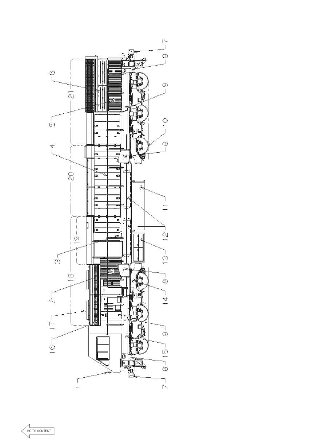
1)

 H

ead l

ight


2)

 I

ner

ti

al

 Fi

lt

er

 A

ir

 I

nl

et


3)

 S

ta

rt

ing

 Fuse

 and

 B

at

ter

K

ni

fe

 S

w

it

ch


4)

 H

andr

ai

ls


5)

 C

ool

ing S

yst

e

m

 A

ir

 I

nl

et


6)

 R

adi

at

o

r and

 Fan A

cc

ess


7)

 C

oupl

er

 “

E

/F

” T

yp

e


8)

 S

andi

ng B

ox

 (

8

9)

 Ja

c

ki

ng P

ads 

(4)


10)

W

heel

(6

11)

Fuel

 Tank


12)

C

om

pr

esse

d

 A

ir

 S

y

st

e

m

 M

ai

n R

ese

rvo

ir

s


13)

B

at

ter

B

ox


14)

Tr

ucks

 (

3

 axl

e 3 

m

o

tor

 H

TS

C

 t

yp

e)

 Q

ty

. 2


15)

U

nder

 f

ram

e


16)

D

yn

am

ic 

B

rake

 G

ri

ds


17)

D

yn

am

ic 

B

rake

 Fans

 (

2


IRCAMTECH/2006/M/D/GM loco/1.0                                                                                   

20


Introduction hand book on GM locomotive                                                       February 2006 


1)

 E

lect

ri

ca

l C

ont

rol

 C

abi

net


2)

 Fuel

 P

u

m

p


3)

 E

ngi

ne S

ta

rt

ing

 M

o

tor

s


4)

 Tr

act

ion C

on

tr

ol

 C

abi

net


5)

 Tr

act

ion 

M

o

tor

 C

ool

ing A

ir

 B

lo

we

6)

 M

ai

n G

ener

a

tor

/C

om

p

ani

on 

A

lt

er

nat

o

B

low

er


7)

 E

ngi

ne E

xh

aus

t S

tack


8)

 E

ngi

ne E

xh

aus

M

ani

fol

d


9)

 16

-710G

3B

 D

iese

l E

ngi

ne


10)

 G

ove

rno

11)

 E

ngi

ne 

room

 V

ent


12)

 E

ngi

ne 

W

at

e

r Tank


13)

 Lube

 O

il C

ool

er


14)

 P

ri

m

ar

y

 Fuel

 Fi

lt

er


15)

 A

ir

 C

om

pr

e

sso

16

R

adi

at

o

rs


17)

 A

C

 R

adi

at

o

r C

ool

ing 

Fans 

(2

18)

 D

ra

ft

 G

ear


19)

 A

ir

 C

om

pr

e

sso

r A

ir

 F

ilt

er


20)

 Lube

 O

il Fi

lt

er

 Tank


21)

 Lube

 O

il S

tr

ai

ner


22)

 Lube

 O

il S

u

m

p


23)

 M

ai

n G

ener

a

tor

C

o

m

pani

on 

A

lt

er

na

tor


24)

 E

lect

ri

ca

l C

ont

rol

 C

abi

net

 A

ir

 Fi

lt

e

r B

ox


25)

 T

ract

ion M

ot

o

rs

 (

6)


IRCAMTECH/2006/M/D/GM loco/1.0                                                                                   

21


Introduction hand book on GM locomotive                                                       February 2006 

1)

 A

ir

 B

rake

 R

ack


2)

 E

ngi

neer

s

 C

ont

rol

 C

o

nso

le


3)

 C

ab D

oo

4)

 Tr

act

ion C

on

tr

ol

 C

abi

net

s


5)

 I

ner

ti

al

 A

ir

 Fi

lt

er

s


6)

 TC

C

 E

lect

roni

cs 

B

low

er


7)

 E

ngi

ne A

ir

 Fi

lt

er


8)

 R

adi

at

o

rs


9)

 E

ngi

ne


10)

 A

C

 A

uxi

liar

G

ene

rat

or


11)

 I

ner

ti

al

 Fi

lt

er

 D

us

t B

in B

lo

w

er

 and M

o

tor


12)

 E

lect

ri

ca

l C

ont

rol

 C

abi

net


13)

 C

ab S

ea

t


IRCAMTECH/2006/M/D/GM loco/1.0                                                                                   

22


Introduction hand book on GM locomotive                                                       February 2006 


FUEL OIL SYSTEM 


The fuel oil system is designed to supply fuel to the 

engine in correct quantity and at the right time according to 
the engine requirements. The fuel oil system draws fuel from 
fuel tank, filter the fuel, pressurise the fuel, and inject the fuel 
into the engine in correct quantity in atomised condition. 

•  Fuel oil system consist of  

1.  Fuel feed system  
2.  Fuel injection system 


Fuel feed system: -  

Fuel is drawn from the fuel oil tank through a suction 

strainer by the fuel pump. The strainer separates foreign 
particles from the fuel oil, and protects the fuel pump. The 
pump is designed to supply adequate quantity of fuel to the 
engine at various speeds and load conditions. 


LINE DIAGRAM OF THE FUEL OIL SYSTEM 


Content   ..  5  6  7  8   ..