Lotus Eleven/Elise/Exige. Manual - part 36


  Index      Lotus     Lotus Eleven/Elise/Exige (engine 1ZZ/2ZZ/1ZR) - service repair manual 2004 year


Search            


Content   ..  34  35  36  37   ..


Lotus Eleven/Elise/Exige. Manual - part 36


Page 19


Lotus Service Notes   


     Section EH

VALVEMATIC System

  The principle of the VALVEMATIC system is that a conventional inlet camshaft with a single (rotary) cam 

for each cylinder operates a roller arm on a pivot shaft.  On each side of the roller arm is an oscillating cam, 

each of which opens, via a finger follower, one of two conventional inlet valves for that cylinder.  The two valves 

are operated at all times as a pair.  The connection between the roller arm and the two oscillating cams is made 

via a common pivot sleeve machined with three separate sections of helical splines, which correspond with 

splines in the bores of the roller arm and oscillating cams.  By sliding the sleeve axially, within the roller arm 

and cams, the opposite helix angle used for the cams compared with that for the roller arm, results in a phase 

shift between arm and cams.  

A 'lost motion' damper ensures that the roller arm stays in contact with the rotary cam profile at all times.  

The position of the oscillating cams at the start of a valve opening event however, is dependent on their phasing 

with the roller arm.  In the low lift mode, where the cams are phased counterclockwise in relation to the roller 

arm as viewed from the rear, the finger follower roller is in contact with the base circle of the oscillating cam, 

which must turn through a large part of its range before the cam starts to lift the valve, resulting in only the first 

portion of the cam profile being used.  In high lift mode, the oscillating cams are phased clockwise in relation to 

the roller arms such that the cam profile immediately starts to lift the valve as soon as the roller arm is depressed 

by the rotary cam, continuing then to utilise the full profile of the oscillating cam for maximum lift.

The concomitant variation in valve timing as the lift changes, is managed by the separate VVT-i system 

(see earlier).

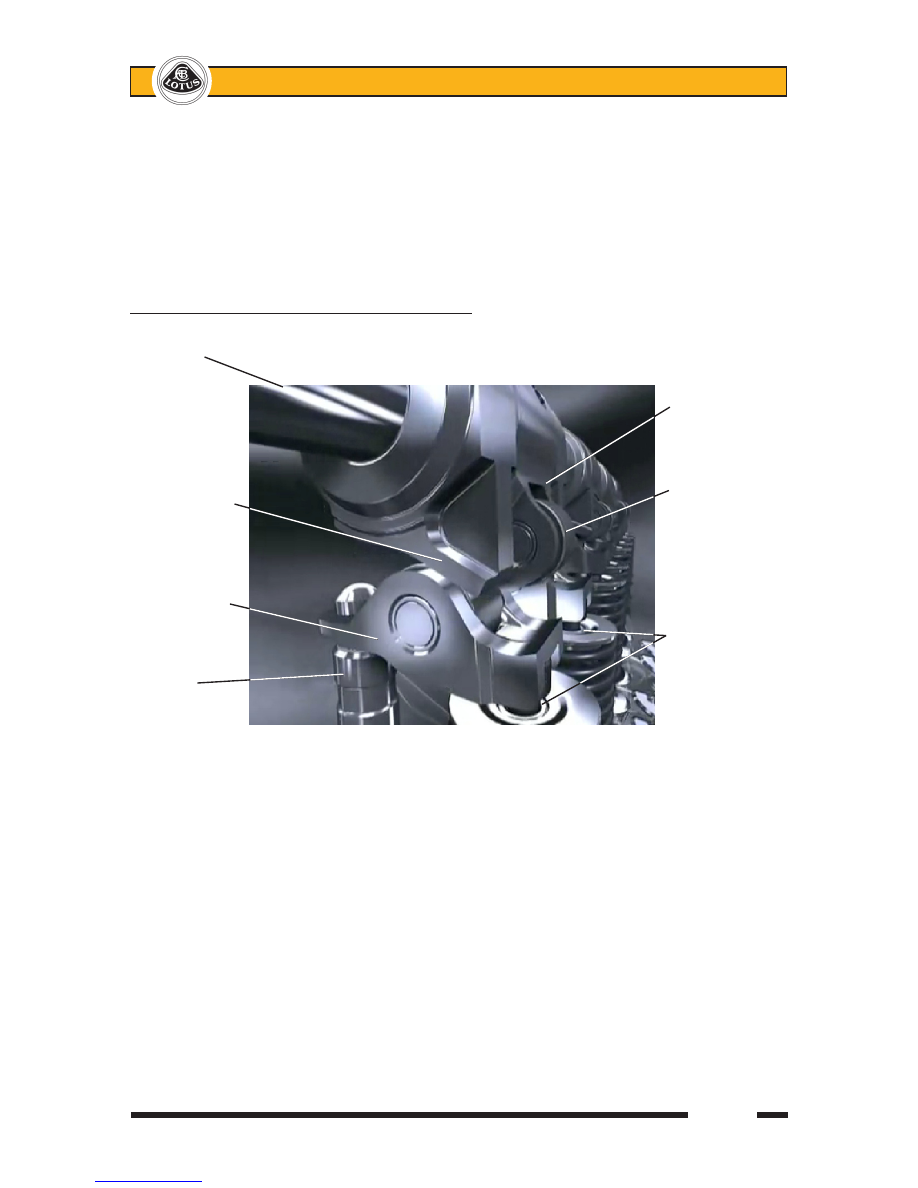
Valves shown at full lift (camshaft omitted for clarity)

Pivot shaft

                                                        Roller arm

                                                        Camshaft 

Oscillating cam                                              operates against

                                                        this roller

Finger follower

                                                        Inlet valves

Hydraulic 

pivot post

Page 20


Lotus Service Notes   


     Section EH

Auxiliary Belt Tension

The auxiliary belt tension on the 1ZR FAE engine is set manually by adjusting the alternator position.  An 

adjusting screw for this purpose is provided on the alternator strap, and may be utilised after slackening the 

strap anchor and clamp bolts, and the alternator lower pivot bolt.

Belt tension should be set using a frequency meter between the water pump and alternator pulleys:

New belt; 110 Hz (± 5 Hz).  Used belt; 90 - 100 Hz.

Alternatively, a force meter can be used on the lower belt run between the crankshaft and water pump:

New belt; 700 - 800 N.  Used belt; 550 - 770 N.

If no meter is available, apply firm thumb pressure to the midpoint of the belt run between water pump and 

alternator, and measure the deflection:

New belt; 7 - 8 mm.  Used belt; 8 - 10 mm.

Engine Lubrication

For optimum engine protection, the oil level should be maintained towards the dipstsick top mark, not be 

allowed to fall below the mid-point. If driving on a closed circuit track, or exploiting maximum cornering capabil-

ity, it is especially important to maintain at the upper marking.  Adding approximately ½ litre will raise the level 

from the mid-point to the upper mark.  

- The oil filter is a cartridge type paper element  

similar in concept to the Evora, and is mounted 

at the right hand rear of the engine, accessible 

from  beneath  after  removal  of  the  engine  bay 

undertray.  

- Make provision for collecting the small amount of 

spilled oil before fitting adaptor tool T000T1441F 

over the cap to release the security catch, and 

allow it to be unscrewed using a 17mm wrench, 

or 3/8 inch square drive.  Release about 4 turns 

before positioning the triple rib feature on the cap 

lowermost; this will aid draining of the oil from the 

filter housing.  Then complete the removal of the 

cap, and dispose of the paper filter element and 

cap ‘O’ ring safely.

Clean the oil filter cap and inside of the filter housing.  Carefully fit a new ‘O’ ring (supplied with the new 

filter) into its groove on the cap and smear with clean engine oil before inserting a new filter element and refit-

ting the cap, taking care to avoid cross-threading, and ensuring that the ‘O’ ring is not displaced.  Using adaptor 

tool T000T1441F, tighten the cap to 25 Nm.

Engine Repair

An engine repair CD is available under part number T000T1523F.  For a technical overview, choose:

New Car Features

2008/11 Update

New Features

1ZR-FAE and 2ZR-FAE Engine

Then select from the drop-down menu as required.

For repair procedures, choose:

Repair Manual

Engine

scroll down past diagnostic codes to find 1ZR-FAE ENGINE MECHANICAL in left hand column.

                      Paper

                      element 

                    ‘O’ ring

  Adaptor    Align triple    Filter cap

  tool      rib lowermost

        to drain housing      

                    OIL FILTER (1ZR)    

ohs175


Lotus Service Notes   


  Section EMP

Page 1

ENGINE MANAGEMENT

SECTION EMP

                                                     Sub-Section   Page

    Diagnostic Trouble Code List                              EMP.1    3

    Diagnostic Scanner Tools                                 EMP.2    43

    Engine Management Component Location                      EMP.3    47

    Mechanical Throttle Setting Procedure                         EMP.4    48

    2006 Model Year Electronic Throttle Control                      EMP.5    49

    Diagnostic Trouble Code Supplement - '06 M.Y.                   EMP.6    50

    Diagnostic Trouble Code Supplement - 2011 M.Y. Elise (Euro 5)         EMP.7    58  

Page 2


Lotus Service Notes   


  Section EMP

EMP.1 - DIAGNOSTIC TROUBLE CODE LIST

DTC    Fault description                                                Page

P0011    Camshaft Position - Timing Over-Advanced or System Performance                 4

P0012   Camshaft Position - Timing Over-Retarded                                 4

P0076  Intake Valve Control Solenoid Circuit Low                                 4

P0077  Intake Valve Control Solenoid Circuit High                                4

P0101  Mass or Volume Air Flow Circuit Range/Performance                           5

P0102  Mass or Volume Air Flow Circuit Low Input                                5

P0103  Mass or Volume Air Flow Circuit High Input                                5

P0106  Manifold Absolute Pressure/Barometric Pressure Circuit Range/Performance           7

P0107  Manifold Absolute Pressure/Barometric Pressure Circuit Low Input                  7

P0108  Manifold Absolute Pressure/Barometric Pressure Circuit High Input                 7

P0111   Intake Air Temperature Sensor 1 Circuit Range/Performance                     8

P0112   Intake Air Temperature Sensor 1 Circuit Low                                8

P0113   Intake Air Temperature Sensor 1 Circuit High                               8

P0116   Engine Coolant Temperature Circuit Range/Performance                        10

P0117   Engine Coolant Temperature Circuit Low                                  10

P0118   Engine Coolant Temperature Circuit High                                 10

P0121  Throttle Position Sensor 'A' Circuit Range/Performance                         12

P0122  Throttle Position Sensor 'A' Circuit Low                                   12

P0123  Throttle Position Sensor 'A' Circuit High                                   12

P0128  Coolant Thermostat (Coolant Temperature Below Thermostat Regulating Temperature)    14

P0131  O2 Sensor Circuit Low Voltage (Pre Catalyst)                              15

P0132  O2 Sensor Circuit High Voltage (Pre Catalyst)                              15

P0133  O2 Sensor Circuit Slow Response (Pre Catalyst)                            15

P0134  O2 Sensor Circuit No Activity Detected (Pre Catalyst)                          15

P0135  O2 Sensor Heater Circuit (Pre Catalyst)                                  15

P0137  O2 Sensor Circuit Low Voltage (Post Catalyst)                              18

P0138  O2 Sensor Circuit High Voltage (Post Catalyst)                              18

P0139  O2 Sensor Circuit Slow Response (Post Catalyst)                            18

P0140  O2 Sensor Circuit No Activity Detected (Post Catalyst)                         18

P0141  O2 Sensor Heater Circuit (Post Catalyst)                                  18

P0171  System Too Lean                                                20

P0172  System Too Rich                                                20

P0201  Injector Circuit/Open – Cylinder 1                                      21

P0202  Injector Circuit/Open – Cylinder 2                                      21

P0203  Injector Circuit/Open – Cylinder 3                                      21

P0204  Injector Circuit/Open – Cylinder 4                                      21

P0300  Random/Multiple Cylinder Misfire Detected                                22

P0301  Cylinder 1 Misfire Detected                                          22

P0302  Cylinder 2 Misfire Detected                                          22

P0303  Cylinder 3 Misfire Detected                                          22

P0304  Cylinder 3 Misfire Detected                                          22

P0324  Knock Control System Error                                         24

P0327  Knock Sensor 1 Circuit Low                                          24

P0328  Knock Sensor 1 Circuit High                                         24

P0335  Crankshaft Position Sensor “A” Circuit Range/Performance                      25

P0340  Camshaft Position Sensor “A” Circuit                                    26

P0351  Ignition Coil “A” Primary/Secondary Circuit                                27

P0352  Ignition Coil “B” Primary/Secondary Circuit                                27

P0353  Ignition Coil “C” Primary/Secondary Circuit                                27

P0354  Ignition Coil “D” Primary/Secondary Circuit                                27

P0420  Catalyst System Efficiency Below Threshold                               28

P0441  Evaporative Emission System Incorrect Purge Flow                          29

P0442  Evaporative Emission System Leak Detected (small leak)                       29


Content   ..  34  35  36  37   ..