Lotus Eleven/Elise/Exige. Manual - part 34


  Index      Lotus     Lotus Eleven/Elise/Exige (engine 1ZZ/2ZZ/1ZR) - service repair manual 2004 year


Search            


Content   ..  32  33  34  35   ..


Lotus Eleven/Elise/Exige. Manual - part 34


Page 11


Lotus Service Notes   


     Section EH

Remove the filter by  turning in a counterclock-

wise direction, if necessary using an oil filter 

wrench, and dispose of safely.  

Ensure that only a Lotus specified filter is 

fitted, as parts with identical outward appear-

ance  can  contain  different  internal  features.  

Before  fitting  a  new  filter,  clean  the  mating 

face on the engine, and smear the new seal 

on the filter with clean oil.  Add a small amount 

of clean engine oil into the filter, screw onto 

its  spigot  and  tighten  BY  HAND  sufficiently 

to  make  a  secure  seal,  typically  2/3  to  3/4 

of a turn after the sealing faces have made 

contact.  

Overtightening using a filter wrench may damage the canister and/or complicate subsequent removal.  

Start the engine and check for oil leaks.  Re-check the security of the filter, further tightening by hand if 

necessary.  Check the oil level (see above) when the engine is fully warm.

Oil Coolers

The foregoing oil change procedure does not disturb the oil quantity contained in the twin oil coolers and 

associated pipework, but is considered perfectly satisfactory for routine maintenance operations.  In instances 

of major engine failure where the oil system may be contaminated with metallic debris, all oil cooler lines should 

be thoroughly flushed out and the oil cooler radiators replaced.

If the oil cooler circuit is drained or re-

placed,  the  following  procedure  should  be 

adopted to fill the cooler system before starting 

the engine: 


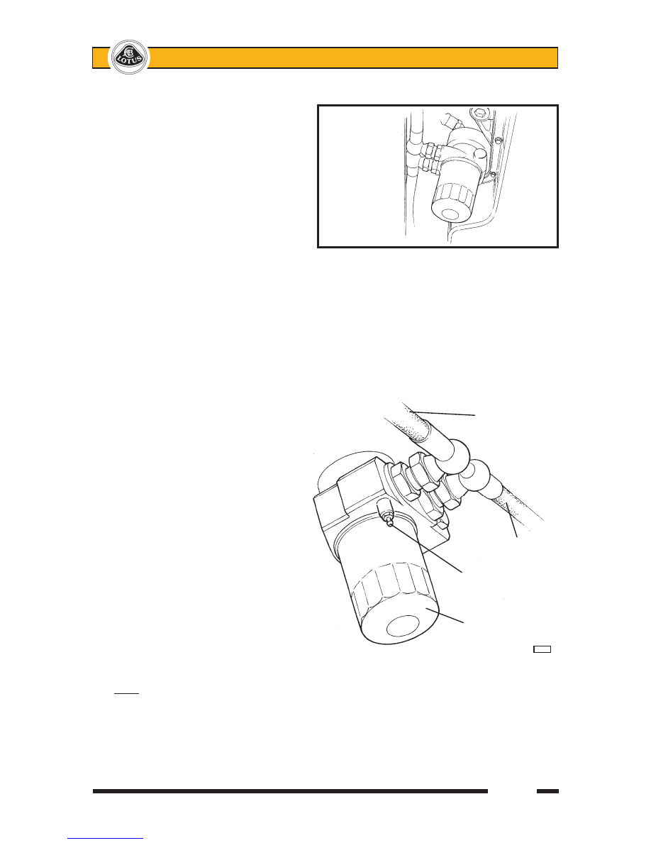
1.  Attach a tube to the bleed nipple on the 

sandwich  plate  between  oil  filter  and 

engine block, and lead into a catch tank.  

Open the bleed nipple.

2.  Disconnect the outlet hose from the top of 

the LH oil cooler, and pour engine oil into 

the cooler until oil reaches the bleed nip-

ple (approx. 2.5 litres).  Close the bleed 

nipple, tightening to 8 Nm.

3.  Connect  the  LH  cooler  outlet  hose  and 

tighten to 40 Nm.

4.  Add a further 0.7 litres of oil into the engine 

to accommodate the volume of the return 

hose between LH oil cooler and engine.

5.  After starting the engine, restrict running to 

idle speed for a minimum of 5 minutes, to 

allow the oil cooler lines to be purged of 

air.  Stop engine and re-check oil level.

Note: For cars fitted with an Accusump pressurised oil storage canister, refer to section 'Exige SC'.


                          Oil cooler 

                          feed hose

                            Oil cooler    

                            return hose


                        Sandwich plate

                        bleed nipple


                       Oil filter canister


e228

OIL FILTER 

(Viewed

from 

beneath)


 ohs129


Lotus Service Notes   


     Section EH

Page 12

Air Cleaner Element

The air filter should be inspected at intervals dependent on the operating conditions.  When the vehicle is 

operated in a relatively clean environment, the element should be renewed at intervals specified in the Main-

tenance Schedule,  but where a dusty or smog laden atmosphere prevails, or other factors contribute to filter 

contamination, more frequent replacement will be required dependent on the level of pollution.


A  disposable  folded  paper  type  air 

cleaner element is fitted in a housing at the 

left hand front of the engine bay.  For access 

to the element, the left hand rear wheel and 

wheelarch liner must first be removed.  Before 

opening the air cleaner housing, the wheelarch 

area should be cleaned to reduce the possibil-

ity of filter or housing contamination with road 

dirt. 


To open the filter housing, release the 

two  spring  clips  at  the  outboard  end  of  the 

housing, and hinge open sufficiently to allow 

the element to be withdrawn.  

Clean the inside of the housing, including the joint faces, taking care not to contaminate the ‘clean’ engine 

side of the assembly.  Fit the new filter element into position with the shallow side facing the 'clean', engine 

side of the housing.  Ensure that the hinge lugs at the inboard end of the housing are correctly engaged before 

closing the housing and securing with the two spring clips.  Refit the wheelarch liner and rear wheel. 

Auxiliary Drive Belt

A single multi-rib serpentine type belt is used to transmit drive from the crankshaft to the water pump, 

alternator and a.c. compressor, with a slave pulley fitted in place of the power steering pump used in other 

applications.  A hydraulically damped, spring loaded tensioner arm applies tension to the back of the belt, and 

is maintenance free.  The belt itself should be inspected for condition at each service interval, and if it exhibits 

any evidence of physical damage, cracking, fraying, perishing, abrasion or contamination, it should be replaced.  

In the case of oil or coolant contamination, the cause must be identified and rectified, and each of the pulleys 

must be thoroughly degreased before the new belt is fitted.

For further details, refer to section CH in the Engine Repair Manual, but note that only a six-sided socket 

should be used on the cast boss on the tensioner arm.  Due to the manufacturing draft angle of the casting, a 

twelve point socket is liable to cause damage.

Spark Plugs

The ignition system uses a distributorless ignition system (DIS) which employs an individual high tension 

coil for each of the four spark plugs.  Each coil is mounted directly onto its spark plug using an integral connector 

and is secured to the cam cover with a single screw.  The spark plugs use small diameter centre electrodes made 

of iridium for long life and high performance, and require changing only at 54,000 mile (90,000 km) intervals.

For further details, refer to section IG in the Engine Repair Manual.

AIR CLEANER

ELEMENT


   ohs146

Page 13


Lotus Service Notes   


     Section EH

EH.4 - ENGINE REMOVAL/REPLACEMENT

It is recommended to remove the rear clamshell prior to powertrain removal in order to improve access, 

and to reduce the possibility of paint damage.  The engine may be removed from above, with or without the 

transmission.  The following procedure applies to the engine/transmission assembly, but to avoid disturbing 

the suspension, refer to sub-section FJ.5 to separate the engine from the transmission before withdrawing the 

engine alone. 

Fuel Pressure Relief Procedure

This procedure should be used prior to disconnecting any part of the fuel line.  

Pull out the fuel pump fuse (on the left 

hand side of the engine bay bulkhead, as 

shown), start the engine, and run until it 

stops from starvation.  Crank the engine 

for a further few seconds.

If the engine is a non-runner, pull out the 

fuel  pump  fuse,  and  crank  the  engine 

for 20 seconds to minimise residual fuel 

pressure.

Disconnect the battery.


It  is  recommended  first  to  release  the 

quick fit connector located to the rear of 

the coolant header tank:

Release the retaining clip securing the 

pipe joint to the header tank bracket.

Slide the orange coloured safety lock to 

allow  access  to  the  connector  release 

buttons.

Surround the pipe joint with a shop towel 

to absorb fuel contained in the pipework 

before pressing the release buttons and 

separating the joint. 


WARNING: Be aware of the possibility of full pressure retention in the fuel line caused by a system 

fault.

Before re-making the joint, ensure that the or-

ange safety lock is fitted onto the pipe connector 

in the orientation shown in the illustration.

Push the male pipe end fully into the female 

connector until a click is heard.  Pull on the pipe 

to ensure complete engagement.

Slide the orange safety lock over the connector 

to prevent accidental pressing of the release 

buttons.

Secure the pipe/connector using the pipe clip 

on the header tank bracket.


Fuel pump 

fuse (20A)


ohs136


Fuel pipe to 

Orange   


engine

safety lock

Fuel pipe 

from tank


Release


button

L64


Lotus Service Notes   


     Section EH

Page 14

1.  Remove the engine bay undertray and diffuser, both rear road wheels and the rear clamshell (see sub-

section BR.7).

2.  On a.c. cars, recover refrigerant and disconnect both a.c. hoses from the pipes at the rear of the RH 

sill.


From beneath the car:

3.  Drain coolant, transmission oil and, if necessary, engine oil.  Diconnect the coolant inlet hose from the 

thermosat housing and cap both apertures.  Disconnect the two oil cooler hoses from the sandwich plate 

and cap all ports and hoses. 

4.  Disconnect the exhaust manifold from the downpipe.

5.  Release the gear cable routing clips from beneath the engine.  Disconnect the earth braid between chas-

sis and transmission.

6.  Release the clutch slave cylinder from the transmission housing and support aside.

7.  Release the steady mounting between the front of the engine and the chassis, and between the rear of 

the engine and the subframe.


From above:

8.  Release the gearchange cables from the transmission by removing the 'R' clips retaining the inner cable 

eyes, and the 'C' clips retaining the outer cables.

9.  Disconnect the air intake hose between air cleaner and intake plenum, and release the brake servo vacuum 

hose from the intake plenum.

10.  Disconnect the throttle cable.  Disconnect the radiator feed hose and heater feed hose from the rear end of 

the cylinder head.  Disconnect the heater return hose from the water rail, and the two hoses and electrical 

connector from the header tank.  Disconnect the re-circ. pump hose to the chassis pipe, and release the 

electrical connector.  Unplug the engine harness.  Release the header tank bracket from the subframe, 

and remove the bracket complete with tank and recirc. pump.  Release the purge pipe from the throttle 

body.

11.  Remove the LH driveshaft from the transmission:


Release the top ball joint plinth from the LH hub carrier noting and retaining the camber adjustment shims, 

and separate the toe-link ball joint separated from the carrier.  The driveshaft inboard joint is retained in 

the transmission by a round section circlip.  The joint may be removed by applying a shock pull to the C.V. 

joint body using a slide hammer with a forked end.  Take great care not to damage the output oil seal on 

withdrawal.


CAUTION:  Do NOT attempt to remove the inboard C.V. joint from the transmission by pulling on the 

driveshaft.  The balls of the inboard joint are restrained for transit purposes only, by a circlip at the end 

of the ball tracks.  Applying an extension force to the joint will damage the balls and require joint replace-

ment.  Apply pressure only to the outer body of the joint.  Do not allow the brake hose to be stetched or 

stressed, and support the driveshaft after withdrawal to protect the shaft joints and hub carrier.  Cap the 

driveshaft aperture in the transmission.

12.  Remove the RH driveshaft from the transmission:


Release the top ball joint plinth from the RH hub carrier noting and retaining the camber adjustment shims, 

and separate the toe-link ball joint separated from the carrier.  The right hand driveshaft incorporates 

a bearing for the extension shaft and it is this which retains the shaft in the transmission.  Remove the 

two bolts ecuring the bearing bracket, and withdraw the complete shaft assembly taking great care not 

to damage the ouput oil seal.  Do not allow the brake hose to be stetched or stressed, and support the 

driveshaft after withdrawal to protect the shaft joints and hub carrier.  Cap the driveshaft aperture in the 

transmission.


Content   ..  32  33  34  35   ..