Seat Mii. Service Manual - part 2


  Index      Seat     Seat Mii. Service Manual


Search            copyright infringement  


Content      ..      1      2      3      ..


Seat Mii. Service Manual - part 2


-------------------------------------------------------------------------------------------------------------------------------------------------------------
The essentials

Lights and visibility

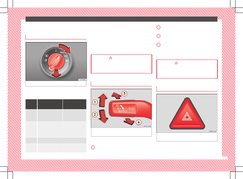
Light switch

Fig. 29 

Dash panel: light control.

Turn the switch to the required position

››› 

Fig. 29

.

Sym-

bol

Ignition switched
off

Ignition is
switched on

Fog lights, dipped
beam and side lights
off.

Light off or daytime
driving light on.



The “Coming Home”
and “Leaving Home”
guide lights may be
switched on.

Automatic control of
dipped beam and
daytime running
light.

Side light on.

Dipped beam head-
light off

Dipped beam
switched on.

 Front fog lights: move the switch to the

first position, from positions ,  or .

 Rear fog light: move the switch completely

from positions ,  or .

Switching off fog lights: Push the switch or
turn it to the  position.

››› 

 in Switching lights on and off on

page 104

››› 

page 103

Turn signal and main beam lever

Fig. 30 

Turn signal and main beam lever in

their initial position

More the lever to the required position:

Right turn signal: Right-hand parking
light (ignition switched off).

1

Left turn signal: Left-hand parking light
(ignition switched off).
Main beam switched on: Control lamp 
lit up on the instrument panel.
Headlight flasher: lit up when the lever is
pushed. Control lamp  lit up.

Lever all the way down to switch it off.

››› 

 in Turn signal and main beam lever

on page 105

››› 

page 105

Hazard warning lights

Fig. 31 

Dash panel: switch for hazard warn-

ing lights.

Switched on, for example:

When approaching a traffic jam

»

2

3

4

21

-------------------------------------------------------------------------------------------------------------------------------------------------------------

-------------------------------------------------------------------------------------------------------------------------------------------------------------

The essentials

In an emergency

The vehicle has broken down

When towing or being towed

››› 

 in Hazard warning lights on

page 106

››› 

page 106

Interior lights

Side lights: Function

Switching off the reading light.

Switching on the reading light.

Switches door contact control on (central po-
sition).
The reading light comes on automatically
when the vehicle is unlocked, a door is
opened or the key is removed from the igni-
tion.
The light goes off a few seconds after all the
doors are closed, the vehicle is locked or the
ignition is switched on.

Note

The reading lights go out when the vehicle is
locked, or a few minutes after the key is re-
moved from the ignition. This prevents the
vehicle's battery from discharging.

Windscreen wipers and window wiper
blade

Fig. 32 

Operating the windscreen wiper and

rear wiper

More the lever to the required position:

0



Windscreen wiper off.

1

Windscreen interval wipe.

2



Slow wipe.

3



Continuous wipe.

4



Brief wipe - short wipe. Hold the lever
down for more time to increase the wipe
frequency.

5

Automatic wipe for cleaning wind-
screens with the lever up.

6

Interval wipe for rear window. The wiper
will wipe the window approximately ev-
ery six seconds.

More the lever to the required position:

7

Automatic wipe for cleaning rear win-
dows with the lever pressed.

››› 

page 108

››› 

page 45

SEAT information system

Introduction

With the ignition switched on it is possible to
access different messages via the display on
the instrument panel display.

The number of messages displayed on the in-
strument panel display will vary according to
the vehicle electronics and equipment.

A specialised workshop will be able to pro-
gramme or modify additional functions, ac-
cording to the vehicle equipment. SEAT rec-
ommends taking your car in for technical
service.

WARNING

Any distraction may lead to an accident, with
the risk of injury.

22

-------------------------------------------------------------------------------------------------------------------------------------------------------------

-------------------------------------------------------------------------------------------------------------------------------------------------------------

The essentials

Do not consult the messages on the instru-

ment panel screen when driving.

Management of indications on the
display

Fig. 33 

Windscreen wiper lever: control but-

tons.

Calling up options

Switch the ignition on.

If a message or vehicle symbol is dis-

played, press 

OK/RESET

 (

››› 

Fig. 33


A

).

Press the top or bottom part of the rocker

switch 

››› 

Fig. 33


B

 until the desired option

appears.

Multifunction display (MFI)

The multifunction display (MFD) has two au-
tomatic memories: 

1 - Partial memory and 2 -

Total memory. The selected memory will be
shown in the lower right-hand corner of the
display.

With the ignition switched on, and memory 1 or
2 displayed, briefly press 

OK

 to change from

one memory to another.

1

Trip memo-
ry (for a
single jour-
ney).

The memory stores the values for the
journey and the consumption from
the moment the ignition is switched
on until it is switched off again.
If the journey is broken for more than
2 hours, the memory is automatically
erased. If the journey is continued in
less than 2 hours after the ignition is
switched off, the new data is added to
the data already stored in the memo-
ry.

2

Total mem-
ory (for all
journeys).

The memory stores the values of any
number of journeys, until it counts a
total of 19 hours and 59 minutes of
driving, or 1999.9 km or miles of driv-
ing, depending on the type of instru-
ment panel fitted. On reaching either
of these limits, the memory is auto-
matically erased and starts to count
from 0 again.

Possible displays

Menu

Function

Time

Current time in hours (h) and minutes
(min).

Travelling
time

This indicates the hours (h) and mi-
nutes (min) since the ignition was
switched on.

Current
fuel con-
sumption

The current fuel consumption display
operates throughout the journey, in
l/100 km; with the engine running
and the vehicle stopped, in l/hour.

Average
fuel con-
sumption

After turning on the ignition, average
fuel consumption in litres/100 km will
be displayed after travelling about
100 metres. Otherwise horizontal
lines are displayed. The value shown
is updated approximately every 5 sec-
onds.

Operating
range

Approximate distance in km that can
still be travelled with the fuel remain-
ing in the tank, assuming the same
style of driving is maintained. This is
calculated using the current fuel con-
sumption.

Distance
covered

Distance travelled, after ignition is
switched on, in km.

Average
speed

The average speed will be shown after
a distance of about 100 metres has
been travelled. Otherwise horizontal
lines are displayed. The value shown
is updated approximately every 5 sec-
onds.

»

23

-------------------------------------------------------------------------------------------------------------------------------------------------------------

-------------------------------------------------------------------------------------------------------------------------------------------------------------

The essentials

Menu

Function

Digital
display of
speed

Current speed displayed digitally.

Liquid
coolant
temperature
digital
display

Digital display of the current tempera-
ture of the engine liquid coolant.

Warning at
--- km/h

If the stored speed is exceeded (be-
tween 30 - 250 km/h, or 18 -
155 mph), an audible warning is giv-
en together with a visual warning.

Changing between display modes

Press the rocker switch in the windscreen

wiper lever.

Storing a speed for the speed warning

Select the display 

Speed warning at

--- km/h

.

Press 

OK

 on the windscreen wiper lever to

store the current speed and switch off the
warning.

In addition, set the required speed by

pressing the rocker switch on the windscreen
wiper lever or 

 or 

 buttons on the multi-

function steering wheel for 5 seconds. Next,
press 

OK

 again or wait a few seconds. The

speed is stored and the warning activated.

To switch off, press 

OK

. The stored speed is

deleted.

Manually erasing memory 1 or 2

Select the memory to be erased.

Press and hold the eject button 

OK

 for ap-

proximately 2 seconds.

Cruise control

Operating the cruise control system
(CCS)*

Fig. 34 

Switches and controls for operating

the CCS

Switching on the CCS: Move switch

››› 

Fig. 34


1

 to . The system is on. If no

speed has been programmed, the system will
not control it.

Activating the CCS: Press button 

››› 

Fig. 34

2

 in the  area. The current speed is

memorised and controlled.

Temporarily switching off the CCS: Move

switch 

››› 

Fig. 34


1

 to  or push the

brake. The cruise control system is switched
off temporarily.

Reactivating the CCS: Press button

››› 

Fig. 34


2

 in . The memorised speed

is saved and controlled again.

Increasing stored speed during CCS regula-

tion: press button 

2

 in . The vehicle ac-

celerates until the new stored speed.

Reducing stored speed during CCS regula-

tion: press button 

2

 in  to lower the

speed by 1 km/h (1 mph). Speed is reduced
until reaching the new stored speed.

Switching off the CCS: Move switch

››› 

Fig. 34


1

 to . The system is disconnec-

ted and the memorised speed is deleted.

››› 

 in Cruise control operation on

page 156

››› 

page 155

Warning lamps

On the instrument panel

The control and warning lamps are indicators
of warnings, 

››› 

, faults 

››› 

 or certain func-

tions. Some control and warning lamps come
on when the ignition is switched on, and

24

-------------------------------------------------------------------------------------------------------------------------------------------------------------

-------------------------------------------------------------------------------------------------------------------------------------------------------------

The essentials

switch off when the engine starts running, or
while driving.

When certain control and warning lamps are
lit, an audible warning is also heard.

Handbrake applied.

››› 

page 

137


Do not continue driving!

The brake fluid level is too low or
there is a fault in the brake system.

it lights up: 


Do not continue

driving!
The liquid coolant level is too low,
the engine liquid coolant tempera-
ture is too high or
there is a fault in the liquid coolant
system.

››› 

page 

191

flashes: engine coolant system
faulty.

››› 

page 

191


Do not continue driving!

Engine oil pressure too low.

››› 

page 

188



lights up or flashes: 


Do not con-

tinue driving!
Fault in the steering.

››› 

page 

133

On the instrument panel: driver or
passenger has not fastened seat
belt.

››› 

page 

52

Faulty generator.

››› 

page 

196

Vehicles with the Start-Stop sys-
tem: it is necessary to start the en-
gine manually.

››› 

page 

161

it lights up: ESC* faulty or switched
off by the system. 

ALTERNATIVELY:

flashes: ESC* or ASR regulating.

››› 

page 

137

it lights up: Traction Control* faulty
or switched off by the system. 

AL-

TERNATIVELY:
flashes: Traction Control* regulator
operating.

ABS faulty or does not work.

Rear fog light switched on.

››› 

page 

103

lights up or flashes: fault in the
emission control system.

››› 

page 

151



Fault in engine management.



lights up or flashes: fault in the
steering system.

››› 

page 

133

Fuel tank almost empty.

››› 

page 

182

The natural gas tank is almost
empty.

››› 

page 

182

Fault in airbag system and seat
belt tensioners.

››› 

page 

59

Tyre pressure* too low

››› 

page 

205

Left or right turn signal.

››› 

page 

103

Hazard warning lights on.

››› 

page 

70

Cruise control operating.

››› 

page 

155

Main beam on or flasher on.

››› 

page 

103

The natural gas engine coolant
temperature is too low.

››› 

page 

192

Lamps on the instrument panel display

A passenger in the rear seats
has fastened their seatbelt.

››› 

page 

52

A passenger in the rear seats
has not fastened their seat
belt.

››› 

page 

52

flashes quickly: the City Safety
Assist system function* brakes
automatically or has braked au-
tomatically. 

Or:

flashes slowly: City Safety As-
sist function is not currently
available.

››› 

page 

156

 

The City Safety Assist* function
has been connected manually.
It switches off after 5 seconds.

››› 

page 

156

 

flashes: The City Safety Assist*
function has been manually
disconnected.

››› 

page 

156



after the ignition is switched
on: indication that the end of
the period for an inspection to
be performed is approaching.

››› 

page 

88

»

25

-------------------------------------------------------------------------------------------------------------------------------------------------------------

-------------------------------------------------------------------------------------------------------------------------------------------------------------

The essentials

it lights up: the Start-Stop sys-
tem is enabled. 

ALTERNATIVE-

LY:
flashes: the Start-Stop system
is not available.

››› 

page 

161

The Start-Stop system is ena-
bled but the engine cannot be
automatically stopped.

flashes in addition to the rest
of the segments of the fuel
gauge: Fuel tank almost empty.

››› 

page 

182

WARNING

If the warning lamps are ignored, the vehicle
may stall in traffic, or may cause accidents
and severe injuries.

Never ignore the warning lamps.

Stop the vehicle safely as soon as possible.

Park the vehicle away from traffic and en-

sure that there are no highly flammable ma-
terials under the vehicle that could come into
contact with the exhaust system (e.g. dry
grass, fuel).

A faulty vehicle represents a risk of acci-

dent for the driver and for other road users. If
necessary, switch on the hazard warning
lamps and put out the warning triangle to ad-
vise other drivers.

Before opening the bonnet, switch off the

engine and allow it to cool.

In any vehicle, the engine compartment is a

hazardous area and could cause severe inju-
ries 

››› 

page 186

.

CAUTION

Failure to heed the warning lamps when they
appear may result in faults in the vehicle.

Gearbox lever

Manual gearbox

Fig. 35 

Gear shift pattern of a 5-speed man-

ual gearbox

The position of each of the gears is shown on
the gear stick 

››› 

Fig. 35

.

Keep the clutch pedal pushed all the way

down.

Move the gearbox lever to the required po-

sition 

››› 

 in Manual gear change on

page 145

.

Release the clutch pedal to engage clutch.

Selecting reverse gear

Engage reverse gear only when the vehicle

is stopped.

Keep the clutch pedal pushed all the way

down 

››› 

 in Manual gear change on

page 145

.

Place the gearbox lever into neutral and

push the lever downwards.

Slide the gearbox lever to the right, and

then backward as shown on the lever.

Release the clutch pedal to engage clutch.

››› 

 in Manual gear change on page 145

››› 

page 145

Automatic gearbox

Fig. 36 

Automatic gearbox diagram of gears

26

-------------------------------------------------------------------------------------------------------------------------------------------------------------

-------------------------------------------------------------------------------------------------------------------------------------------------------------

The essentials

Reverse gear
Neutral (idling)
Drive (forward)

R
N
D

Tiptronic mode: pull the lever forwards
(

+) to go up a gear or backwards () to

go down a gear.

M

››› 

 in Automatic gear change on

page 146

››› 

page 145

Air conditioning

How does Climatronic work*?

Fig. 37 

At the top of the centre console: Clima-

tronic controls

Switching off

The system disconnects by pushing the lower button several times  

››› 

Fig. 37



Cooling mode
The cooling mode is connected and disconnected with the  button.



Automatic mode
The automatic mode is connected and disconnected with the  button. The automatic mode is initiated by maintaining a constant temperature in
the passenger compartment. Air temperature, amount and distribution is automatically regulated. The automatic mode is disconnected, if the venti-
lation is manually changed.

Temperature

Buttons 

1

 and 

2


››› 

Fig. 37

 regulate the temperature. The set temperature is shown on the screen.

»

27

-------------------------------------------------------------------------------------------------------------------------------------------------------------

-------------------------------------------------------------------------------------------------------------------------------------------------------------

The essentials

Blower
The speed of the blower is set with the button  

››› 

Fig. 37

.

Air distribution

The air distribution ,  or  

››› 

Fig. 37

 is set with the buttons

Air distribution towards the upper part of the body through the air vents on the dash panels

Air distribution to footwells

Air distribution towards the windscreen and the footwell

Air distribution towards the windscreen

Removing ice from the windscreen
The ice is removed from the windscreen  

››› 

Fig. 37

 the fastest possible way and it is also cleaned with the button (defrosting/demisting

function). When the temperature is above +3 °C (+38 °F), the air is dehumidified and increases the blower speed.

Air recirculation
The air recirculation  

››› 

Fig. 37

 is connected and disconnected with the button 

››› 

page 130

.

Rear window defroster
The rear  window defroster located on the top of the centre console, is connected and disconnected while the engine is in gear. The rear window
defroster is automatically disconnected after a maximum of 10 minutes have lapsed.

››› 

 in Introduction on page 130

››› 

page 130

28

-------------------------------------------------------------------------------------------------------------------------------------------------------------

-------------------------------------------------------------------------------------------------------------------------------------------------------------

The essentials

How does the manual air conditioning and heating and fresh air system work?

Fig. 38 

At the top of the centre console: manual

air conditioning and heating and fresh air system
controls.

Switching off

it is disconnected by turning the main control 

2

 to position  

››› 

Fig. 38



Cooling mode

a)

The cooling mode is connected and disconnected with the  button.

Temperature

The temperature is set with left rotary control 

1


››› 

Fig. 38

.

Blower
The speed of the blower is set with main rotary control 

2


››› 

Fig. 38

.

Air distribution

With right rotary control 

3


››› 

Fig. 38

 the air distribution is set

Air distribution towards the upper part of the body through the air vents on the dash panels

Air distribution to footwells

Air distribution towards the windscreen and the footwell

Air distribution towards the windscreen

»

29

-------------------------------------------------------------------------------------------------------------------------------------------------------------

-------------------------------------------------------------------------------------------------------------------------------------------------------------

The essentials

Removing the ice from the windscreen
The ice is removed  

››› 

Fig. 38

 from the windscreen and cleans the windscreen the quickest possible way with the right rotary control (defrost-

ing/demisting function).

Air recirculation
With scrollable control 

4


››› 

Fig. 38

 the air distribution is connected and disconnected 

››› 

page 130

.

Rear window defroster
The rear  window defroster located on the top of the centre console, is connected and disconnected while the engine is in gear. The rear window
defroster is automatically disconnected after a maximum of 10 minutes have lapsed.

a)

Valid for vehicles with manual air conditioning.

››› 

 in Introduction on page 130

››› 

page 130

30

-------------------------------------------------------------------------------------------------------------------------------------------------------------

-------------------------------------------------------------------------------------------------------------------------------------------------------------

The essentials

Fluid Level control

Filling the fuel tank

Fuel tank capacity

Petrol engines

Around 35.0 l,

of which approximately 4.0 are the

reserve.

Natural gas en-
gine

Natural gas: approx. 11 kg; of which

max. 1.5 kg reserve

Petrol: approx. 10 l; of which approx.

5 l reserve

Windscreen washer tank capacity

The washer bottle capacity is approximately 3 litres.

Fuel

Fig. 39 

Open fuel tank flap with tank cap in

the holder

Opening the fuel tank cap
The tank flap is at the rear of the vehicle on
the right.

Pull the rear zone of the fuel tank flap to

open.

Unfold the key shaft if necessary

››› 

page 92

.

Insert the vehicle key into the lock cylinder

of the fuel tank plug and turn the key in an
anticlockwise direction.

Take out the fuel tank plug by turning it in

an anticlockwise direction and rest it on the
upper part of the fuel tank flap 

››› 

Fig. 39

.

Closing the fuel tank cap

Screw on the fuel tank filler plug in a clock-

wise direction until it is fully inserted with a
click.

Insert the vehicle key into the lock cylinder

of the fuel tank plug, turn the key in a clock-
wise direction and remove the key.

Press the tank flap until you hear it click in-

to place. The tank flap must be flush with the
body contour.

››› 

 in Introduction on page 183

››› 

page 185

Oil

Fig. 40 

Engine oil dipstick.

Fig. 41 

In the engine compartment: Engine

oil filler cap.

The level is measured using the dipstick loca-
ted in the engine compartment.

The oil should leave a mark between zones

A

 and 

C

. It should never exceed zone 

A

.

Zone 

A

: Do not add oil.

»

31

-------------------------------------------------------------------------------------------------------------------------------------------------------------

-------------------------------------------------------------------------------------------------------------------------------------------------------------

The essentials

Zone 

B

: You can add oil but keep the level

in that zone.

Zone 

C

: Add oil up to zone 

B

.

Topping up engine oil

Unscrew cap from oil filler opening.

Add oil slowly.

At the same time, check the level to ensure

you do not add too much.

When the oil level reaches at least zone 

B

,

unscrew the engine oil filler cap carefully.

Specifications of engine oil with a service de-
pendent on time/distance travelled

44 kW - 55 kW Petrol en-
gines

VW 504 00, VW 502 00

Natural gas engine

VW 502 00

››› 

 in Topping up engine oil on

page 191

››› 

page 188

Coolant

Fig. 42 

Engine compartment: coolant expan-

sion tank cap.

The coolant tank is located in the engine
compartment.

When the engine is cold, replace the coolant
when the level is below .

Coolant specifications
The engine cooling system is supplied from
the factory with a specially treated mixture of
water and at least 40 % of the additive 

G13

(TL-VW 774 J), purple. This mixture gives the
necessary frost protection down to -25 °C
(-13 °F) and protects the light alloy parts of
the engine cooling system against corrosion.
It also prevents scaling and considerably rai-
ses the boiling point of the coolant.

To protect the cooling system, the percentage
of additive must always be at least 40 %,

even in warm climates where anti-freeze pro-
tection is not required.

If for weather reasons further protection is
necessary, the proportion of additive may be
increased, but only up to 60 %; otherwise an-
tifreeze protection will diminish and this will
worsen cooling.

When the coolant is topped up, use a mixture
of 

distilled water and at least 40 % of the

G13 or G12 plus-plus (TL-VW 774 G) additive
(both are purple) to obtain an optimum anti-
corrosion protection 

››› 

 in Checking the

coolant level and topping up on page 194

.

The mixture of G13 with G12 plus (TL-VW 774
F), G12 (red) or G11 (green-blue) engine cool-
ants will significantly reduce anti-corrosion
protection and should therefore be avoided

››› 

 in Checking the coolant level and top-

ping up on page 194

.

››› 

 in Checking the coolant level and

topping up on page 193

››› 

page 191

32

-------------------------------------------------------------------------------------------------------------------------------------------------------------

-------------------------------------------------------------------------------------------------------------------------------------------------------------

The essentials

Brake fluid

Fig. 43 

Engine compartment: brake fluid res-

ervoir cap

The brake fluid reservoir is located in the en-
gine compartment.

The level should be between the  and 
marks. If it is below , please visit a Techni-
cal Service.

››› 

 in Checking the brake fluid level on

page 194

››› 

page 194

Windscreen washer

Fig. 44 

In the engine compartment: wind-

screen washer reservoir top.

The windscreen washer reservoir is located in
the engine compartment.

To top up, mix water with a product recom-
mended by SEAT.

In cold temperatures, add anti-freeze for the
windshield cleaner.

››› 

 in Checking and topping up the

windscreen washer reservoir with water
on page 195

››› 

page 195

Battery

The battery is located in the engine compart-
ment. It does not require maintenance. It is
checked as part of the Inspection Service.

››› 

 in Introduction on page 196

››› 

page 196

33

-------------------------------------------------------------------------------------------------------------------------------------------------------------

-------------------------------------------------------------------------------------------------------------------------------------------------------------

The essentials

Emergencies

Fuses

Fuse location

Fig. 45 

On the driver-side dash panel: fuse

box cover

Fig. 46 

In the engine compartment: fuse box

cover

Underneath the instrument panel
The fuse box is located underneath the dash
panel on the driver side 

››› 

Fig. 45

.

In the engine compartment
Press the locking tabs to release the fuse box
cover 

››› 

Fig. 46

.

Identifying fuses situated below the dash
panel by colours

Colour

Amp rating

Purple

3

Light brown

5

Brown

7.5

Red

10

Blue

15

Yellow

20

White or transparent

25

Green

30

Orange

40

››› 

 in Introduction on page 78

››› 

page 78

Replacing a blown fuse

Fig. 47 

Image of a blown fuse

Preparation

Switch off the ignition, lights and all elec-

trical equipment.

Open the corresponding fuse box

››› 

page 79

.

Identifying a blown fuse
A fuse is blown if its metal strip is ruptured

››› 

Fig. 47

.

Point a lamp at the fuse to see if the fuse has
blown.

To replace a fuse

Remove the fuse.

Replace the blown fuse by one with an

identical amperage rating (same colour and
markings) and identical size.

34

-------------------------------------------------------------------------------------------------------------------------------------------------------------

-------------------------------------------------------------------------------------------------------------------------------------------------------------

The essentials

Replace the cover again or close the fuse

box lid.

Bulbs

Bulbs (12 V)

Light source used for each function

Halogen headlights

Type

Daytime running light/side
light

W21/5W

Dipped beam headlights

H4 LL

Main beam headlights

H4 LL

Turn signal

PY21W NA

Front fog light

Type

Fog/cornering lights*

HB4

Rear bulb light

Type

Brake/side lights

P21/5W LL

Side lights

P21/5W LL

Turn signal

PY21W NA LL

Retro fog light

P21W

Reverse lights

R10W

Action in the event of a punc-
ture

What to do first

Park the vehicle on a horizontal surface

and in a safe place as far away from traffic as
possible.

Apply the handbrake.

Switch on the hazard warning lights.

Manual gearbox: select the 1st gear.

Automatic gearbox: position the selector

lever to 

D or R.

If you are towing a trailer, unhitch it from

your vehicle.

Have the vehicle tool kit 

››› 

page 71

and the spare wheel* ready

››› 

page 206

.

Observe the applicable legislation for each

country (reflective vest, warning triangles,
etc.).

All occupants should leave the vehicle and

wait in a safe place (for instance behind the
roadside crash barrier).

WARNING

Always observe the above steps and pro-

tect yourself and other road users.

If you change the wheel on a slope, block

the wheel on the opposite side of the car with

a stone or similar to prevent the vehicle from
moving.

Repairing a tyre with the anti-punc-
ture kit

Fig. 48 

Standard representation: contents of

the anti-puncture kit.

The anti-puncture kit is located under the
floor panel in the luggage compartment.

Sealing the tyre

Unscrew the tyre valve cap and insert. Use

the 

››› 

Fig. 48


1

 tool to remove the insert.

Place it on a clean surface.

Shake the tyre sealant bottle vigorously

››› 

Fig. 48


10

.

»

35

-------------------------------------------------------------------------------------------------------------------------------------------------------------

-------------------------------------------------------------------------------------------------------------------------------------------------------------

The essentials

Screw the inflator tube 

››› 

Fig. 48


3

 into

the sealant bottle. The bottle's seal will break
automatically.

Remove the lid from the filling tube

››› 

Fig. 48


3

 and screw the open end of the

tube into the tyre valve.

With the tyre sealant bottle upside down,

fill the tyre with the contents of the sealant
bottle.

Remove the bottle from the valve.

Place the insert back into the tyre valve us-

ing the tool 

››› 

Fig. 48


1

.

Inflating the tyre

Screw the compressor tyre inflator tube

››› 

Fig. 48


5

 into the tyre valve.

Check that the air bleed screw is closed

››› 

Fig. 48


7

.

Start the engine and leave it running.

Insert the connector 

››› 

Fig. 48


9

 into the

vehicle's 12-volt socket 

››› 

page 121

.

Turn the air compressor on with the ON/OFF

switch 

››› 

Fig. 48


8

.

Keep the air compressor running until it

reaches 2.0 to 2.5 bar
(29-36 psi/200-250 kPa). 

A maximum of 8

minutes.

Disconnect the air compressor.

If it does not reach the pressure indicated,

unscrew the tyre inflator tube from the valve.

Move the vehicle 10m so that the sealant is

distributed throughout the tyre.

Screw the compressor tyre inflator into the

valve.

Repeat the inflation process.

If the indicated pressure still cannot be

reached, the tyre is too badly damaged. Stop
and request assistance from an authorised
technician.

Disconnect the air compressor. Unscrew

the tyre inflator tube from the tyre valve.

When the tyre pressure is between 2.5 and

2.0 bars, continue driving without exceeding
80 km/h (50 mph).

Check the pressure again after 10 minutes

››› 

page 74

.

››› 

 in TMS (Tyre Mobility System)* on

page 73

››› 

page 72

Changing a wheel

Vehicle tool kit

Fig. 49 

Components of the vehicle tool kit

Screwdriver with hexagon socket in the
handle
Adapter for anti-theft bolt.
Towline anchorage, removable.
Wire hook for removing the hub caps.
Jack.
Wheel spanner.
Wheel bolt cap clips.

››› 

 in What to do first on page 35

››› 

page 70

1

2

3

4

5

6

7

36

-------------------------------------------------------------------------------------------------------------------------------------------------------------


Content      ..      1      2      3      ..