Seat Mii. Service Manual - part 1


  Index      Seat     Seat Mii. Service Manual


Search            copyright infringement  


Content      ..       1      2      ..


Seat Mii. Service Manual - part 1


-------------------------------------------------------------------------------------------------------------------------------------------------------------

The essentials

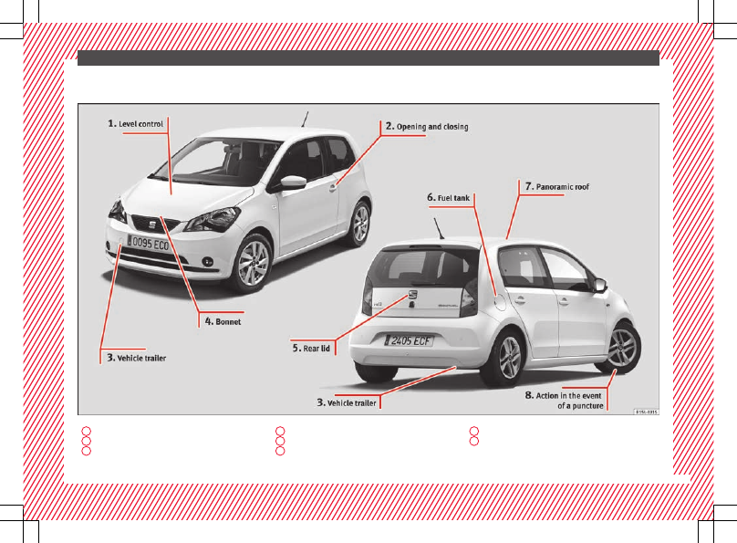
Exterior view

1


››› 

page 31

2


››› 

page 8

3


››› 

page 42

4


››› 

page 10

5


››› 

page 9

6


››› 

page 31

7


››› 

page 11

8


››› 

page 35

5

-------------------------------------------------------------------------------------------------------------------------------------------------------------

-------------------------------------------------------------------------------------------------------------------------------------------------------------

The essentials

Exterior view

1


››› 

page 31

2


››› 

page 33

3


››› 

page 33

4


››› 

page 34

5


››› 

page 31

6


››› 

page 32

7


››› 

page 33

8


››› 

page 36

9


››› 

page 35

6

-------------------------------------------------------------------------------------------------------------------------------------------------------------

-------------------------------------------------------------------------------------------------------------------------------------------------------------

The essentials

Interior view (left guide)

1


››› 

page 13

2


››› 

page 21

3


››› 

page 21

4


››› 

page 24

5


››› 

page 24

6


››› 

page 22

7


››› 

page 22

8


››› 

page 21

9


››› 

page 8

10


››› 

page 15

11


››› 

page 20

12


››› 

page 27

13


››› 

page 26

14


››› 

page 11

15


››› 

page 34

16


››› 

page 10

17


››› 

page 14

18


››› 

page 12

7

-------------------------------------------------------------------------------------------------------------------------------------------------------------

-------------------------------------------------------------------------------------------------------------------------------------------------------------

The essentials

How it works

Unlocking and locking

Doors

Fig. 1 

Remote control key: buttons.

Fig. 2 

In the driver door: central locking but-

ton

Locking and unlocking the vehicle using the
key

Locking: press the  

››› 

Fig. 1

 button.

Unlocking: press the  

››› 

Fig. 1

 button.

Unlocking the rear lid: hold down the 

››› 

Fig. 1

 button for at least 1 second.

Locking and unlocking with the central lock-
ing switch

Locking: press the  

››› 

Fig. 2

 button. None

of the doors can be opened from the outside.
The doors can be opened from the inside by
pulling the inside door handle.

Unlocking: press the  

››› 

Fig. 2

 button.

››› 

 in Introduction on page 94

››› 

page 94

››› 

page 9

Locking and unlocking the driver door
manually

Fig. 3 

Driver door release lever with lock cyl-

inder.

As a general rule, when the driver door is
locked all other doors are locked. Unlocking
manually only opens the driver door.

Unfold the key shaft if necessary

››› 

page 92

.

Insert the key shaft into the lock cylinder to

unlock or lock the vehicle 

››› 

Fig. 3

.

8

-------------------------------------------------------------------------------------------------------------------------------------------------------------

-------------------------------------------------------------------------------------------------------------------------------------------------------------

The essentials

Locking the passenger door manually

Fig. 4 

To the front of the passenger side door:

Emergency lock, hidden by a rubber cap.

Fig. 5 

Emergency locking of the vehicle using

the vehicle key

The passenger door can be manually locked.

Open the door.

Remove the rubber cap to the front of the

door. The rubber cap is marked with a lock
symbol  

››› 

Fig. 4

.

Unfold the key shaft if necessary

››› 

page 92

.

Insert the key shaft horizontally into the

opening and moved the coloured lever for-
ward 

››› 

Fig. 5

.

Replace the rubber cap and close the door.

Check if the door is locked.

Have the vehicle checked by a specialised

workshop.

Note

The doors can be opened and unlocked indi-
vidually from the inside by pulling the inside
door handle. If necessary, pull the inner door
release lever twice 

››› 

page 94

.

Rear lid

Fig. 6 

Rear lid open: hand grip

Opening

Press the button 

 on the vehicle key

››› 

Fig. 1

 for about one second to unlock the

boot hatch.

Insert the vehicle key into the lock cylinder

of the driver door and turn the key 

in an anti-

clockwise direction 

››› 

page 94

.

Closing

Grab the handgrip inside the rear lid

››› 

Fig. 6

 (arrow).

Push the rear lid downwards until it locks

into place in the lock.

Ensure that it is correctly closed by pulling

on it firmly.

››› 

 in Introduction on page 99

››› 

page 99

››› 

page 10

9

-------------------------------------------------------------------------------------------------------------------------------------------------------------

-------------------------------------------------------------------------------------------------------------------------------------------------------------

The essentials

Emergency unlocking the boot hatch

Fig. 7 

From the luggage compartment: Emer-

gency unlocking of the booth hatch.

If necessary, fold the rear seat bench back-

rest forward 

››› 

page 12

.

Remove equipment to access the inside of

the rear lid.

Unfold the key shaft 

››› 

page 92

.

Insert the key shaft into the rear lid open-

ing 

››› 

Fig. 7

 and press the release lever in the

direction of the arrow to unlock the rear lid.

Bonnet

Fig. 8 

A: Release lever in the footwell on the

driver side B: Release lever on the bonnet

Fig. 9 

C: Bonnet securing rod in the bonnet.

D: Bonnet supported by the bonnet securing
rod

Opening the bonnet

Before opening the bonnet, make sure that

the windscreen wiper arms are in place
against the windscreen 

››› 

 in Working in

the engine compartment on page 188

.

10

-------------------------------------------------------------------------------------------------------------------------------------------------------------

-------------------------------------------------------------------------------------------------------------------------------------------------------------

The essentials

Pull the release lever 

1

 in the direction of

the arrow 

››› 

Fig. 8


A. The bonnet is released

from the lock carrier by a spring mechanism

››› 

 in Working in the engine compartment

on page 188

.

Lift the bonnet up slightly while pressing

the release lever 

2


B in the direction of the

arrow to completely open the bonnet.

Take out the bonnet support rod from its

clip in the direction of the arrow 

3


C and

place it in the corresponding open position

4


D (arrow).

Closing the bonnet

Slightly lift the bonnet 

››› 

 in Working in

the engine compartment on page 188

.

Take out the bonnet support rod from the

opening catch 

4


D and insert it into its clip

3


C in the opening catch.

Let the bonnet fall from a height of 30 cm

into its clip; Do not apply pressure!

If the bonnet is not correctly closed, open it
once again and close it correctly.

The bonnet is correctly closed when it is flush
with the corresponding parts on the body-
work.

››› 

 in Working in the engine compart-

ment on page 186

››› 

page 186

Electric windows*

Fig. 10 

In the driver door: buttons for the

front electric windows

Opening the window: Press the  button.

Closing the window: Pull the  button.

Window on the front left door
Window on the front right door

››› 

 in Opening and closing the electric

windows on page 101

1

2

Panoramic sunroof*

Fig. 11 

In the interior roof: turn the knob to

open and close

Fig. 12 

In the interior roof: press or pull the

knob to raise the sunroof and close it.

To raise the sliding/tilting sunroof, the knob
must be in the basic position 

1

.

Opening: Turn the switch to position

››› 

Fig. 11


3

.

»

11

-------------------------------------------------------------------------------------------------------------------------------------------------------------

-------------------------------------------------------------------------------------------------------------------------------------------------------------

The essentials

Convenience position: Turn the switch to

position 

››› 

Fig. 11


2

.

Closing: Turn the switch to position

››› 

Fig. 11


1

.

To tilt open: Push the switch to position

››› 

Fig. 12


4

. For an intermediate position,

hold down the switch until you reach the de-
sired position.

Lowering: Pull the switch to position

››› 

Fig. 12


5

. For an intermediate position,

hold down the switch until you reach the de-
sired position.

››› 

 in Opening and closing the panor-

amic sunroof on page 102

››› 

page 102

Before driving

Manually adjusting the seats

Fig. 13 

Front left seat controls

The front seat head restraints are integrated
in the backrests and adjusting them is not
possible.

Forward/back: pull the lever and move
the seat forwards. The front seat must be
engaged when the lever is released!
Raising/lowering: pull the lever up or
push down (several times if necessary)
from its home position.
Tilting the backrest: pull the lever and
adjust the backrest seat angle until you
reach the desired position. The seat back-
rest must be engaged.
Folding/Raising (Easy Entry only in 3-
door vehicles): to fold, pull the lever and
at the same time move the seat forward.

1

2

3

3

To raise it, move the seat back until the
catch engages. Pull the lever and tilt
open the backrest. The backrest must en-
gage in the upright position.

››› 

 in Manual front seat adjustment on

page 112

12

-------------------------------------------------------------------------------------------------------------------------------------------------------------

-------------------------------------------------------------------------------------------------------------------------------------------------------------

The essentials

Adjust the seat belt

Fig. 14 

Positioning and removing the seat

belt buckle.

Fig. 15 

Correct seat belt and head restraint

positions, viewed from front and the side.

To adjust the seat belt around your should-
ers, adjust the height of the seats.

The shoulder part of the seat belt should be
well centred over it, never over the neck. The
seat belt lies flat and fits comfortably on the
upper part of the body.

The lap part of the seat belt lies across the
pelvis, never across the stomach. The seat
belt lies flat and fits comfortably on the pel-
vis.

››› 

 in Introduction on page 52

››› 

page 56

Seat belt tensioners

During a frontal collision, the seat belts on
the front seats retract automatically.

The tensioner can be triggered only once.

››› 

 in Service and disposal of belt ten-

sion devices on page 58

››› 

page 58

Adjusting the exterior mirrors

Fig. 16 

In the driver door: rotary control for

the exterior electric mirrors

Adjusting the exterior mirrors: Turn the knob
to the corresponding position:

Turning the knob to the desired posi-
tion, adjust the mirrors on the driver

»

L/R

13

-------------------------------------------------------------------------------------------------------------------------------------------------------------

-------------------------------------------------------------------------------------------------------------------------------------------------------------

The essentials

side (L, left) and the passenger side (R,
right) to the direction desired.
Depending on the equipment fitted on
the vehicle, the mirrors may be heated
according to the outside temperature.

››› 

 in Exterior mirrors on page 111

››› 

page 111

Adjusting the steering wheel

Fig. 17 

Mechanical steering wheel adjust-

ment

Push the lever 

››› 

Fig. 17


1

 downwards.

Adjust the steering wheel so that you can

hold onto the steering wheel with both hands
on the outside of the ring at the 9 o'clock and

3 o'clock positions and your arms slightly
bent.

Push the lever firmly upwards until it is

flush to the steering column 

››› 

 in Adjust-

ing the steering wheel position on
page 49

.

››› 

 in Adjusting the steering wheel po-

sition on page 49

››› 

page 49

Airbags

Front airbags

Fig. 18 

Location and deployment area of the

front airbag for the driver.

14

-------------------------------------------------------------------------------------------------------------------------------------------------------------

-------------------------------------------------------------------------------------------------------------------------------------------------------------

The essentials

Fig. 19 

Location and deployment area of the

front airbag for the passenger.

In conjunction with the seat belts, the front
airbag system gives the driver and the front
passenger additional protection for the head
and chest in the event of a severe frontal col-
lision. Always remain as far away as possible
from the front airbag 

››› 

page 48

. This

way, in the event of an accident, the front air-

bags can deploy fully when triggered, provid-
ing maximum protection.

The front airbag for the driver is located in
the steering wheel 

››› 

Fig. 18

 and the airbag

for the front passenger is located in the dash
panel 

››› 

Fig. 19

. Airbags are identified by the

word “AIRBAG”.

When the front airbags are triggered they fill
the zones marked in red 

››› 

Fig. 18

 and 

››› 

Fig. 19

 (radius of action). Therefore, ob-

jects should never be placed or mounted in
these areas 

››› 

 in Front airbags on

page 62

, Factory-fitted accessories are out-

side the range of the front airbag for the driv-
er and the front passenger, e.g. the base-
plate for the mobile phone support.

The airbag covers fold out of the steering
wheel 

››› 

Fig. 18

 and the dash panel

››› 

Fig. 19

 when the driver and front passen-

ger airbags, respectively, are triggered.

››› 

 in Front airbags on page 62

Disabling the front passenger front
airbag

Fig. 20 

On front passenger side: Key switch

for enabling and disabling the front passen-
ger front airbag.

The front passenger front airbag must be dis-
abled when a rear-facing child seat is moun-
ted.

Disabling the front passenger front airbag

Switch the ignition off.

Open the door on the front passenger side.

Unfold the vehicle key blade

››› 

page 92

.

Using the vehicle key, turn the key switch to

OFF 

››› 

Fig. 20

.

Close the door on the front passenger side.

The      control lamp on

the dash panel will remain lit while the igni-
tion is switched on 

››› 

page 63

.

»

15

-------------------------------------------------------------------------------------------------------------------------------------------------------------

-------------------------------------------------------------------------------------------------------------------------------------------------------------

The essentials

››› 

 in Manual disabling and enabling of

the front passenger front airbag with the
key switch
 on page 64

››› 

page 63

Side airbags

Fig. 21 

On the side of the front seat: location

of the side airbag

Fig. 22 

On the left side of the vehicle: deploy-

ment area of side airbag

The side airbags are located in the outer
cushion of the driver and front passenger
seat backrests 

››› 

Fig. 21

Their position is in-

dicated by the word “AIRBAG”. The area
marked in red 

››› 

Fig. 22

 indicates the side

airbag deployment zone.

In the event of a side-on collision, the side
airbag will deploy in the side of the vehicle
affected 

››› 

Fig. 22

, thus reducing the risk of

injuries to passengers on the side of the
body and the head facing the accident side.

››› 

 in Side airbags* on page 62

Child seats

Important information regarding the
front passenger's airbag

Fig. 23 

Passenger's side sun visor: airbag

sticker.

Fig. 24 

On the rear frame of the passenger

side door: airbag sticker.

16

-------------------------------------------------------------------------------------------------------------------------------------------------------------

-------------------------------------------------------------------------------------------------------------------------------------------------------------

The essentials

A sticker with important information about
the passenger airbag is located on the pas-

senger's sun visor and/or on the passenger
side door frame.

››› 

 in Important information regarding

the front passenger's airbag on page 65

››› 

page 64

Mounting systems

Fig. 25 

On the rear seats: Possible installations

for the child seat.

Always secure child seats properly and safely
in the vehicle according to the child seat
manufacturer's installation instructions.

Mounted child seats must rest correctly on
the vehicle's seat and must not move or rock
more than 2.5 cm.

Child seats equipped for a Top Tether strap
must also be secured using the Top Tether re-

taining strap in the vehicle 

››› 

page 19

. At-

tach the retaining strap to the corresponding
retaining rings only. Not all rings can be used
with the Top Tether system. Always tighten
the Top Tether retaining strap so that the
child seat fits snugly against the correspond-
ing seat in the vehicle.

Specific mounting systems for each country
Attachment variants
 

››› 

Fig. 25

:

Europe: ISOFIX retaining rings and upper
retaining strap 

››› 

page 18

 and

››› 

page 19

.

Three-point seat belt and upper retaining
strap 

››› 

page 18

.

»

A

B

17

-------------------------------------------------------------------------------------------------------------------------------------------------------------

-------------------------------------------------------------------------------------------------------------------------------------------------------------

The essentials

The systems include the child restraint sys-
tem mounting with an upper retaining strap
(Top Tether) and lower anchoring points on
the seat.

Securing child seats with the seat belt

The seat belt may be used to secure child
seats with the 

universal marking (on the or-

ange label) to the vehicle seats marked with

u in the table below.

Category

Front passen-

ger

a)

Rear seats

Group 0

Up to 10 kg

u

u

Category 0+

Up to 13 kg

u

u

Group 1

9 to 18 kg

u

u

Group 2

15 to 25 kg

u

u

Group 3

22 to 36 kg

u

u

a)

Compliance with current national legislation and the manu-

facturer's instructions is required when using or installing child
seats.

Securing the child seat using the seat belt

Please read and observe the child seat

manufacturer's handling instructions.

Move the front passenger seat, or the rear

seat bench back as far as possible and, in
the case of an adjustable backrest, set it in
the upright position 

››› 

page 48

.

Positioning the child seat on the seat ac-

cording to the manufacturer's instructions.

Fasten the seat belt or pass it around the

child seat structure in the manner described
in the manufacturer's instructions.

Make sure the seat belt is not twisted.

Insert the latch plate into the buckle for the

appropriate seat and push it down until it is
securely locked with an audible click.

Ensure that the upper belt web lies tightly

on the child seat.

Pull the belt (it must be no longer possible

to pull the lower belt webbing out).

Removing the child seat
The seat belt must not be unfastened until
the vehicle has come to a standstill.

Press the red button on the buckle. The

latch plate is released from the buckle.

Guide the belt back by hand so that it rolls

up easily and the trim will not be damaged.

Remove the child seat from the vehicle.

››› 

 in Safety instructions on page 66

Setting up a child seat with the ISO-
FIX system

Fig. 26 

On the vehicle seat: identification var-

iants of the anchor points for the child seats

Each seat of the rear seat bench has 

two re-

tainers named lower anchor points.

Synoptic display for the ISOFIX system in-
stallation
Installation options of the ISOFIX or i-Size
child seats on the ISOFIX anchor points of the
various vehicle seats.

18

-------------------------------------------------------------------------------------------------------------------------------------------------------------

-------------------------------------------------------------------------------------------------------------------------------------------------------------

The essentials

Age group

Class

based on

size

Front pas-

senger

seat

Places for

rear seat

Group 0: up
to 10 kg

E

X

IL-SU

Group 0+:
up to 13 kg

E

X

IL-SU

D

X

C

X

Group 1:
from 9 to
18 kg

D

X

IL-SU

IUF

C

X

B

X

B1

X

A

X

Group 2:
from 15 to
25 kg

X

IL-SU

Group 3:
from 22 to
36 kg

X

IL-SU

i-Size child
restraint
system

X

X

Class based on size: indication of the class

based on the size corresponds to the author-
ized body weight for child seats. The class
based on the size is indicated on child seats
with universal or semi-universal certification

on the ECE certification label. Indication of
the class based on size appears on the corre-
sponding child seat.

X: seat not suitable for installation of an

ISOFIX or i-Size child seat from this group.

IL-SU: suitable seat for installation of an

ISOFIX child seat with a semi-universal certifi-
cate. Please note the list of vehicles from the
child seat manufacturer.

IUF: suitable seat for installation of an ISO-

FIX child seat with a universal certificate.

Child seats with rigid mounting
For the installation of a child seat with rigid
mounting auxiliary introduction elements can
be used. These elements facilitate fitting and
protect the upholstery. They form part of the
supply volume of the child seat or can be ac-
quired at a SEAT dealership. If necessary,
these elements are inserted in both anchor
points of the vehicle 

››› 

 in Safety instruc-

tions on page 66

.

Observe the manufacturer's instructions

when installing and removing the child seat

››› 

 in Safety instructions on page 66

.

Press the child seat onto the retaining rings

››› 

Fig. 26

 in the direction of the arrow. The

child seat must be safely engaged and click
audibly into place.

Pull on both sides of the child seat to en-

sure that it is secure.

Child seat with adjustable retaining straps

Observe the manufacturer's instructions

when installing and removing the child seat

››› 

 in Safety instructions on page 66

.

Place the child seat on the seat cushion

and attach the retaining strap hooks to the
retaining rings 

››› 

Fig. 26

.

Tighten the straps evenly using the corre-

sponding adjustment device. The child seat
must sit flush against the vehicle seat.

Pull on both sides of the child seat to en-

sure that it is secure.

››› 

 in Safety instructions on page 66

Securing a child seat with the Top
Tether retaining strap

Fig. 27 

Example of an upper retaining strap

connected.

»

19

-------------------------------------------------------------------------------------------------------------------------------------------------------------

-------------------------------------------------------------------------------------------------------------------------------------------------------------

The essentials

Observe the manufacturer's instructions

when installing and removing the child seat

››› 

 in Safety instructions on page 66

.

Unlock the seat backrest and fold it gently

forward 

››› 

page 12

.

Remove the head restraints situated be-

hind the child seat and store them safely in
the vehicle 

››› 

page 48

.

Guide the upper retaining strap from of the

child seat back to the luggage compartment,
feeding it through the seat backrest and the
rear shelf.

Fold back the seat backrest and push it

firmly into the lock.

Secure the child seat to the lower anchor

points 

››› 

page 18

Hook the upper retaining strap in the lug-

gage compartment, to the corresponding re-
taining ring 

››› 

Fig. 27

.

Tighten the strap so that the top of the

child seat rests on the seat backrest.

››› 

 in Safety instructions on page 66

Starting the vehicle

Ignition lock

Fig. 28 

Ignition key positions.

Switch ignition on: Place the key in the igni-
tion and start the engine.

Locking and unlocking the steering wheel

Engaging the steering wheel lock: Remove

the key from the ignition and turn the wheel
until it locks. In vehicles with an automatic
gearbox, the gear lever must be in 

N position

in order to remove the key. If necessary,
press the locking key on the selector lever
and release it again.

Unlocking the steering wheel: Put the key

into the ignition and turn it at the same time
as the steering wheel in the direction indica-
ted by the arrow. If it is not possible to turn
the steering wheel, it may be because it is
locked.

Turning on/switching off the ignition, glow
plugs reheating

Switch ignition on: Turn the key to the 

2

position.

Switch ignition off. Turn the key to the 

1

position.

Diesel vehicles : The glow plugs reheat

when the ignition is switched on

Starting the engine

Manual gearbox: press the clutch pedal all

the way down and move the gearbox lever in-
to neutral.

Automatic gearbox: step on the brake ped-

al and put the selector lever in 

N.

Turn the key to the 

3

 position. The key au-

tomatically returns to the 

2

 position. Do not

press the accelerator.

Start-Stop System*
When you stop and release the clutch pedal,
the Start-Stop system* turns off the engine.
The ignition remains switched on.

››› 

 in Switching on the ignition and

starting the engine on page 135

››› 

page 135

20

-------------------------------------------------------------------------------------------------------------------------------------------------------------


Content      ..       1      2     ..