Haima S5 1.5T. Chassis System. Service Manual - part 6


  Index      Haima     Haima S5 1.5T. Chassis System. Service Manual


Search            copyright infringement  


Content      ..     4      5      6      7     ..


Haima S5 1.5T. Chassis System. Service Manual - part 6


Brake system 2F-30 


ABS system parts are correctly connected, 
jammed or slashed. 

  The wires shall be arranged near to high-

voltage or high-current device, e.g.high-voltage 
power or part, generator, motor, and 
stereophonic amplifier attached after sale. 
Note:  the high-voltage or high-current device 
may make the circuit noisy, thus it will disturb 
the normal operation of circuit. 

  ABS parts are very sensitive for 

electromagnetic interference(EMI). In case of 
suspecting the intermittent faults, check 
whether the thief-proof devices, lamps or 
mobile telephones attached after sale are 
correctly installed. 

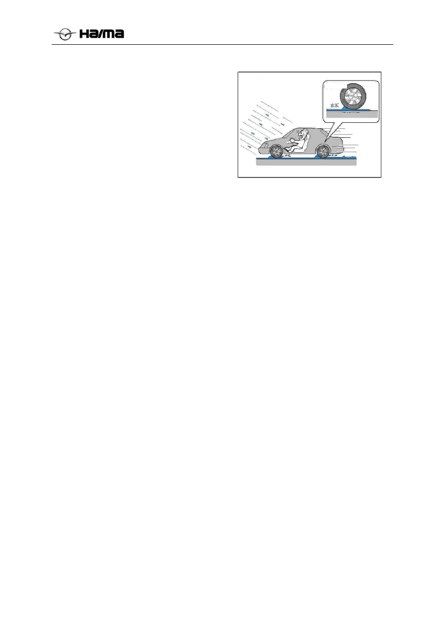
8.  ABS is an active safety system. Its main 

purpose is to adopt the maximum ground 
adhering moment, and keep the steer ability of 
vehicle and drive stability. However, in case of 
exceeding its physical limit or driving on the 
wet and slippery road at high speed, ABS can’t 
prevent the vehicle from slipping fully, too.  

9.  In case of too much noise of ABS, it may be 

caused by the following cases: 

  Loosened fixation of ABS assembly and 

ABS support. 

  Loosened fixation of ABS support and 

vehicle body. 

 

Loss or damages of plastic washers on ABS 
support.


Hydroplaning

Don’t cling

Hydroplanin

-------------------------------------------------------------------------------------------------------------------------------------------------------------


Brake system 2F-31 


Introduction of ABS 9 system 

I.  Composition of ABS 9 system 

As shown in the figure below, ABS 9 consists of hydraulic module with an electronic control unit and 
wheel speed sensor . 


 Wheel speed sensor 

 ABS hydraulic control module of electronic control unit  

Note: this drawing is only for reference. For the detailed positions of elements, please refer to the vehicle 
maintenance manual. 

II.  Hydraulic diagram for Haima S5 ABS 9 X-type arrangement  

The brake system is arranged in X shape. As shown in the figure below, ABS 9 hydraulic regulator 
includes a motor, two return pumps, two energy accumulators and eight solenoid valves.


-------------------------------------------------------------------------------------------------------------------------------------------------------------


Brake system 2F-32 


The following meanings of English abbreviations in Fig.: 

MC1  First circuit of brake master cylinder 

RR 

Right rear wheel 

MC2  Second circuit of brake master cylinder 

FLEV

left front wheel oil inlet valve 

motor 

FLAV

left front wheel oil outlet valve 

RP1 

return pump 1 

FREV

right front wheel oil inlet valve 

RP2 

return pump 2 

FRAV

right front wheel oil outlet valve 

A1 

Energy accumulator 1 

RLEV

Left rear wheel oil inlet valve 

A2 

Energy accumulator 2 

RLAV

Left rear wheel oil outlet valve 

FL 

left front wheel 

RREV

Right rear wheel oil inlet valve 

FR 

right front wheel 

RRAV

Right rear wheel oil outlet valve 

RL 

Left rear wheel 


-------------------------------------------------------------------------------------------------------------------------------------------------------------


Brake system 2F-33 


III.  Haima S5 ABS 9 ECU interface circuit 

3.1  Haima S5 circuit diagram 


-------------------------------------------------------------------------------------------------------------------------------------------------------------


Brake system 2F-34 


3.2  Definitions of Haima S5 pins 

Pin Function 

Motor power terminal(positive) 

Wheel speed output(right front) 

3 EBD 

warning 

lamp 

4  wheel speed sensor signal terminal(right 

front) 

5 Undefined 

Diagnostic K line 

7 Undefined 

8  wheel speed sensor signal terminal(left 

front) 

9 Undefined 

10 Undefined 

11 Undefined 

12 Undefined 

13 Motor 

ground 

terminal 

14  CAN L (unused) 

15 Undefined 

16  wheel speed sensor power terminal (right 

front) 

17  wheel speed sensor power terminal (right 

rear) 

18  wheel speed sensor signal terminal (left 

rear) 

19  wheel speed sensor power terminal (left 

front) 


Pin

Function 

20

Undefined 

21

Undefined 

22

Undefined 

23

Undefined 

24

Undefined 

25

Power end of valve relay 

26

CAN H (unused) 

27

ABS warning lamp 

28

ECU power terminal (ignition power line) 

29

wheel speed sensor signal terminal (right 
rear) 

30

brake lamp switch 

31

wheel speed sensor power terminal (left 
rear) 

32

Undefined 

33

Speed output 

34

Undefined 

35

Undefined 

36

Undefined 

37

Undefined 

38

ECU ground terminal 


-------------------------------------------------------------------------------------------------------------------------------------------------------------


Brake system 2F-35 


ABS 9 Fault diagnosis 

I. Diagnostic 

flow 

The vehicle enters into the repair factory.


Analysis of customers’ problems


3


Reading of fault codes


Faults 


Go to Step 4


No faults 


Go to Step 6


4


Record the fault codes, and then remove the fault codes.


Certification and reproduction of faults: accelerate the vehicle speed up to at least 15 km/h, 
simulate the reproduction of faults, and read the faults again.


Faults 


Current fault code. Go 
to Step 9. 


No faults 


Historical fault code. 
Go to Step 9. 


For the faults without fault codes, repair and go to Step 9. 


Remove the faults as per the list of fault codes, and then go to Step 9. 


Remove the faults as per the list of fault symptoms, and then go to Step 9. 


Confirm the removal of faults, perform the repair and test on completion.


10 

Avoid the regeneration of faults.


Conclusion


-------------------------------------------------------------------------------------------------------------------------------------------------------------


Brake system 2F-36 


II. For the faults without fault codes, repair it. 

If the faults occur to the brake system, but ABS has no stored fault codes, and this fault is called as a fault 
without fault codes. The fault without fault codes is generally caused by basic faults of brake system. E.g.: 

  Leakage of brake fluid (it may cause the softening of brake, overlong stroke of brake pedal, and even 

serious failure of brake) 

  Application of poor brake fluid(the use of poor brake fluid will corrode the brake pipe and elements 

inside ABS hydraulic control module, and lead to the serious failure of brake) 

  Existence of air in brake pipe (it may cause the softening of brake and even brake failure) 

  Blockage of brake pipe (it may cause the hardening of brake and even brake failure) 

  Excessive wears of brake disc (it may cause the softening of brake and even brake failure) 

  Faults of booster (it may cause the hardening or softening of brake, overlong stroke of brake pedal and 

even still brake failure seriously) 

  Wrong connection of brake pipe (it may cause the reduction of ABS performances, whipping and long 

braking distance,etc. For the correct installation methods, please refer to the marks near to oil holes in 
ABS hydraulic control module: MC1 stands for #1 master cylinder oil pipe; MC2 stands for #2 master 
cylinder oil pipe; FL stands for left front wheel cylinder oil pipe; FR stands for right front wheel 
cylinder oil pipe; RL stands for left rear wheel cylinder oil pipe; RR stands for right rear wheel 
cylinder oil pipe) 

Note: no power or power failure of ABS will lead to the constant illumination of ABS warning lamp, but it 
has no fault codes.  

Suggestions for fault removal: check the corresponding parts as per the fault symptoms, and remove the 
faults as per the vehicle maintenance manual.  

III.  Repair of occasional faults 

In the electronic system, the instant poor contact may appear in the electric circuit and input/output signals, 
thus it may cause the occasional faults. Sometimes, the fault causes will disappear automatically, so it’s not 
easy to check these problems. In case of meeting the occasional faults, first read the historical fault codes 
with a diagnostic unit, check the conditions related to fault codes, simulate the faults as per the following 
modes, and check whether the faults are regenerated. 

If no fault is regenerated at this time, its diagnosis and repair must be performed after the regeneration of 
next fault. Generally speaking, the occasional fault will become a reproducible fault gradually, and it won’t 
disappear automatically. 


S/N 

Possible causes of 

faults 

Simulated faults 

Remarks 

When the vibration 
may be a major 
cause 

1. Shake ABS ECU connector lightly 
up, down, left or right. 
2. Shake ABS wire lightly up, down, 
left or right. 
3. Shake the sensor lightly up, down, 
left or right. 
4. Shake other moving parts(e.g. 
wheel bearing) lightly. 

If the wire is twisted off or broken 
due to its excessive tension, it must 
be renewed. 
The wheel speed sensor wire will 
become shortly open-
circuited/short-circuited due to 
upward/downward movement of 
suspension system during the 
movement of vehicle. Therefore, 
the actual driving test of vehicle 
must be performed while checking 
the sensor wires. 

-------------------------------------------------------------------------------------------------------------------------------------------------------------


Brake system 2F-37 


S/N 

Possible causes of 

faults 

Simulated faults 

Remarks 

When the 
temperature may be 
a major cause 

1. Heat the parts with possible faults 
with an air blower. 
2. Check them for cold welding with 
cold spraying agent. 


When the excessive 
electricity load may 
be a major cause 

1. Turn on all the switches of electric 
appliances, including the lamp and 
wiper, to make the power supply of 
vehicle work at high load. 


IV.  Analysis of fault codes 

4.1  List of fault codes 

DTC fault code


Description of fault codes


C190004


High supply voltage of ECU 


C190104


Low supply voltage of ECU


C100004


ECU fault(hardware, tiny errors of controller)


C101008


ECU fault(software error)


C006B06


Inappropriate ABS control(overlong control time)


C003108


Faults of left front wheel speed sensor signals: off-limit, loss, noises, intermittent 
interruptions


C003200


Fault of left front wheel speed sensor wire: open-circuit


C00A000


Fault of left front wheel speed sensor wire: shorted to ground


C00A100


Fault of left front wheel speed sensor wire: shorted to power supply


C00A900


Fault of left front wheel speed sensor: its fault causes can’t be definitely known.


C003408


Faults of right front wheel speed sensor signals: off-limit, loss, noises, intermittent 
interruptions


C003500


Fault of right front wheel speed sensor wire: open-circuit


C00A200


Fault of right front wheel speed sensor wire: shorted to ground


C00A300


Fault of right front wheel speed sensor wire: shorted to power supply


C00AA00


Fault of right front wheel speed sensor: its fault causes can’t be known.


C003708


Faults of left rear wheel speed sensor signals: off-limit, loss, noises, intermittent 
interruptions


C003800


Fault of left rear wheel speed sensor wire: open-circuit


C00A400


Fault of left rear wheel speed sensor wire: shorted to ground


-------------------------------------------------------------------------------------------------------------------------------------------------------------


Brake system 2F-38 


DTC fault code


Description of fault codes


C00A500


Fault of left rear wheel speed sensor wire:shorted to the power supply


C00AB00


Faults of Left rear wheel speed sensor:its fault causes can’t be definitely known.


C003A08


Faults of Right rear wheel speed sensor signals: off-limit, loss, noises, intermittent 
interruptions


C003B00


Fault of Right rear wheel speed sensor wire: open-circuit


C00A600


Fault of Right rear wheel speed sensor wire: shorted to ground


C00A700


Fault of right rear wheel speed sensor wire:shorted to the power supply


C00AC00


Faults of right rear wheel speed sensor: its fault causes can’t be definitely known.


C109904


Fault of wheel speed sensor set(interchange of wheel speed sensor, overhigh 
differences between the wheel speeds, faults of several wheel speed sensor)


C001004


Fault of left front inlet valve


C001104


Fault of left front outlet valve


C001404


Fault of right front inlet valve


C001504


Fault of right front outlet valve


C001804


Fault of left rear inlet valve


C001904


Fault of left rear outlet valve


C001C04


Fault of Right rear inlet valve


C001D04


Fault of right rear outlet valve


C109504


Fault of valve relay


C002004


Fault of return pump motor


C007208


Faults of valve set (overheat protection, disabled signals, hardware damages)


4.2  High or low supply voltage 

Fault setting conditions 

When the supply voltage of ECU conforms to any of the following conditions, this fault will be produced: 

(1)  The voltage of vehicle when starting the power-up vehicle is below 4.5V. 

(2)  When the ignition switch is in On position, the voltage is below 7.7V or above 16.8V. 

(3)  When the vehicle speed is above 6km/h, the voltage is between 7.7V and 9.2V. 

Possible fault causes 

(1)  Overhigh or overlow voltage of battery. 

(2)  Damages of ECU. 

-------------------------------------------------------------------------------------------------------------------------------------------------------------


Brake system 2F-39 


Diagnostic steps 


Step Operation 

Yes 

No 

Is the initial check performed? 

Perform Step 2.

Perform the initial 

check. (see Page 3) 

Measure the voltage of battery. Do you find out the 
faults and remove them? For the definitions of pins, 
refer to the circuit diagram of detailed items. 

Perform Step 4.

Perform Step 3. 

Cross validation of ABS (for its detailed steps, refer 
to Section “Removal and Installation”). In case of 
confirming the damages of ECU, replace ABS. Is the 
fault removed? 

Perform Step 4.

Re-diagnose it, and confirm whether its fault is 
regenerated? 

Completion of 

diagnostic work 

4.3  Faults of solenoid valve and valve set relay 

Fault codes: C001004; C001104; C001404; C001504; C001804; C001904; C001C04; C001D04; 
C109504; C007208 

Fault setting conditions 

(1)  Valve supply faults.(short circuit of power supply to ground or open circuit of earth wire) 

(2)  Overhigh temperature of solenoid valve.(overheat protection) 

(3)  Short circuit of at least 5 solenoid valves(fuses) 

(4)  Actuate the corresponding solenoid valve, but it has no feedbacks. Diagnostic steps 

(5)  Self-faults of solenoid valve. 

(6)  Faults of valve set relay. 

Possible fault causes 

(1)  Short circuit of solenoid valve to power supply or earth, open circuit of wire(poor earthing). 

(2) Fuse 

faults. 

(3)  Overheat protection of system (overlong operating time of solenoid valve, which often occurs in case 

of vacuum filling and off-line check). 

(4) ABS 

damages. 


Step Operation 

Yes 

No 

Cool the vehicle for 5 minutes, and check whether its 
faults are removed? 

Perform Step 2. 

Is the initial check performed? 

Perform Step 3. 

Perform the initial 

check. 

Measure the voltage of power supply pins of solenoid 
valve in connectors, and check the fuses, external 
relays, connectors, wires and earth wires. Are the 
faults found out and removed? For the definitions of 
pins, refer to the circuit diagrams for detailed items. 

Perform Step 5. 

Perform Step 4. 

Cross validation of ABS (for its detailed steps, refer 
to Section “Removal and Installation”). In case of 
confirming the damages of ABS, replace ABS. Is the 
fault removed?  

Perform Step 5. 

-------------------------------------------------------------------------------------------------------------------------------------------------------------


Brake system 2F-40 


Step Operation 

Yes 

No 

Stop the vehicle after increasing its speed up to 
15km/h, re-diagnose it, and confirm whether the fault 
is regenerated?  

Completion of 

diagnostic work 

4.4  Fault of pump motor 

Fault codes: C002004  

Fault setting conditions 

(1)  Overload operation of pump motor, its overhigh temperature (overheat protection) 

(2)  After the return pump motor relay works for 60ms, the return pump monitor can’t still detect any 

voltage signal. 

(3)  The return pump motor relay fails to work, and the return pump monitor detects the voltage of over 2. 

5V. 

(4)  The return pump motor relay stops its operation, the return pump monitor detects no reduction of 

voltage. 

Possible fault causes 

(1)  Poor grounding of pump motor. 

(2)  Overheat protection of system. 

(3)  Abnormality of pump motor power supply(fuse, battery terminal) 

(4)  Faults of pump motor relay. 

(5)  Faults of pump motor. 

Diagnostic steps 


Step Operation 

Yes 

No 

Cool the vehicle for 5 minutes, and check whether its 
faults are removed? 

Perform Step 2. 

Is the initial check performed? 

Perform Step 3. 

Perform the 

initial check. 

Measure the voltage of power supply pins of pump motor 
in connectors, and check the fuses, external relays, 
connectors, wires and earth wires. Are the faults found 
out and removed? For the definitions of pins, refer to the 
circuit diagrams for detailed items.  

Perform Step 5. 

Perform Step 4. 

Cross validation of ABS (for its detailed steps, refer to 
Section “Removal and Installation”). In case of 
confirming the damages of ABS, replace ABS. Is the 
fault removed? 

Perform Step 5. 

Stop the vehicle after increasing its speed up to 15km/h, 
re-diagnose it, and confirm whether the fault is 
regenerated? 

Completion of 

diagnostic work 

4.5  Wheel speed sensor wire 

Fault codes: C003200; C00A000; C00A100; C00A900; C003500; C00A200; C00A300; C00AA00; 
C003800; C00A400; C00A500; C00AB00; C003B00; C00A600; C00A700; C00AC00; C109904 

Fault setting conditions 

(1)  ECU detects that the signal line of wheel speed sensor is shorted to ground. 

-------------------------------------------------------------------------------------------------------------------------------------------------------------


Brake system 2F-41 


(2)  Open circuit of wheel speed sensor wire.  

Possible fault causes 

(1)  Disconnection, loosened connection or fracture of wheel speed sensor wires. 

(2)  Reverse connection of wheel speed sensor signal line and power line. 

(3)  Short circuit of signal line to ground. 

(4)  Damages of sensor head or connection pin. 

Diagnostic steps 


Step Operation 

Yes 

No 

Is the initial check performed? 

Perform Step 2. 

Perform the 

initial check. 

Check whether the wheel speed sensor is perfectly 
connected. Check the open circuit or short circuit of wheel 
speed sensor wires in the harness. Are the faults found out 
and removed? For the definitions of pins, refer to the 
circuit diagrams for detailed items. 

Perform Step 4.  Perform Step 3.

Cross validation of ABS (for its detailed steps, refer to 
Section “Removal and Installation”). In case of confirming 
the damages of ABS, replace ABS. Is the fault removed? 

Perform Step 4. 

Stop the vehicle after increasing its speed up to 15km/h, 
re-diagnose it, and confirm whether the fault is 
regenerated? 

Completion of 

diagnostic work

4.6  Faults of wheel speed sensor signals 

Fault codes: C003108; C00A900; C003408; C00AA00; C003708; C00AB00; C003A08; C00AC00; 
C109904 

Fault setting conditions 

(1)  ECU detects that the signal line of wheel speed sensor is shorted to the power supply. 

(2)  ECU detects that the power line of wheel speed sensor is shorted to ground. 

(3)  Abnormal signals of wheel speed sensor. 

Possible fault causes 

(1)  Disconnection, loosened connection or breakage of wheel speed sensor wires. 

(2)  The signal line of wheel speed sensor is shorted to the power supply. 

(3)  The power line of wheel speed sensor is shorted to ground. 

(4)  Non-installation of gear ring, loss of teeth, dirty gear ring, existence of strange substances, 

demagnetizing, eccentric gear ring. 

(5)  Excessive air gap between the sensor and gear ring. 

(6)  External magnetic field interference of wheel speed sensor (demagnetizing failure of wheel or axle). 

(7)  Faults of wheel speed sensor body. 

(8)  Wrong number of gear ring teeth. 

(9)  Above-normed size of tire. 

(10) Damages of ECU. 

Diagnostic steps 

Note

-------------------------------------------------------------------------------------------------------------------------------------------------------------


Brake system 2F-42 


1)  For the faults of wheel speed sensor signals, after removing the faults, be sure to start the vehicle and 

increase its speed up to about 15km/h, thus ABS warning lamp can go out. 

2)  Don’t measure the supply voltage from the wheel speed sensor to ECU. Once the open circuit of 

wheel speed sensor exists, ECU will stop its power supply automatically, until its power supply is 
recovered after the next ignition self-check.  

4.7 ECU faults 

Fault codes: C100004; C101008 

Fault setting conditions 

(1)  ECU supply fault.  

(2)  Damages of ECU. 

Possible fault causes 

ECU faults 

Diagnostic steps 


Step Operation 

Yes 

No 

Is the initial check performed? 

Perform Step 2. 

Perform the initial 

check. 

Cross validation of ABS (for its detailed steps, refer to 
Section “Removal and Installation”). In case of 
confirming the damages of ABS, replace ABS. Is the 
fault removed? 

Perform Step 3. 

Re-diagnose it, and confirm whether the fault is 
regenerated? 

Completion of 

diagnostic work 

4.8  Unreasonable control of ABS 

Fault codes:C006B06 

Fault setting conditions 

ABS receives the command of continual operation (above 1 minute).  

Possible fault causes 

(1)  Continual braking of ice. 

(2) Overlarge 

wheel 

speed difference. 

Diagnostic steps 


Step Operation 

Yes 

No 

Is the initial check performed? 

Perform Step 2. 

Perform the 

initial check. 

Check the wheel speed sensor and gear ring. Are the 
faults removed? 

Perform Step 4. 

Perform Step 3. 


Cross validation of ABS (for its detailed steps, refer to 
Section “Removal and Installation”). In case of 
confirming the damages of ECU, replace ABS. Is the 
fault removed? 

Perform Step 4. 

Re-diagnose it, and confirm whether the fault is 
regenerated? 

Completion of 

diagnostic work

-------------------------------------------------------------------------------------------------------------------------------------------------------------


Brake system 2F-43 


Removal and installation 

I.  Steps for removing ABS assembly 

1.  Make the ignition switch in OFF position, and disconnect the negative pole of battery. 

2.  Remove the wire from ABS assembly. 

3.  Step the brake pedal to bottom, fix it with a pedal support to prevent the brake fluid from flowing out 

after removing the brake pipe from the brake master cylinder. 

4.  Remove the brake pipe, block the thread hole of ABS assembly and oil hole of brake pipe to avoid the 

entry of impurities. 

5.  Take down ABS from the fixed support. 

II.  Installation steps of ABS assembly 

1.  Install ABS assembly on the support,and tighten it up to the torque of 8±2Nm. 

2.  Take down the plugs from ABS thread hole and brake pipe, connect the brake pipe into ABS assembly, 

and tighten it up to the torque of 16±2Nm. 

3.  Add the brake fluid into fluid reservoir up to Max, and bleed it as per the specified method. 

III. Cross validation 

1.  Remove ABS to install it on another vehicle with the same model and without faults (the oil pipe can’t 

be installed, and only ECU plug is connected, but you must ensure that the plug can’t be loosened 
while the vehicle is driving). 

2.  Drive the vehicle, ensure the vehicle speed is not below 20km/h, and activate the dynamic self-check 

of ABS. 

IV. Exhaust instructions 

The hydraulic unit can be manually exhausted, and any of following three exahust procedures can be 
selected during the repair: 

1.  Exhaust with a filling unit (exhaust pressure of 2bar). 

2.  Exhaust with a manual pedal. 

3.  Combined exhaustion of manual pedal and filling unit. 

 

After the customer replaces the brake system (e.g. replacement of brake fluid, brake pipe or hydraulic 
unit), or the brake pedal is soft, it must be exhausted. 

 

The hydraulic unit replaced by the customer must be a filled ABS hydraulic regulator with ECU. 

 

During the exhaustion, be sure to ensure the complete structure of brake system, and all the high-
pressure hydraulic units have been connected. 

 

It’s required to pull the parking brake before exhausting it. 

 

The brake fluid is corrosive. If it’s affixed to the skin carelessly, it must be removed. 

4.1  Exhaust with an exhaustion/filling unit (exhaust pressure of 2 bar). 

Connect the exhaust/filling unit to the fluid reservoir, confirm that the brake fluid is enough to 

turn on the switch, and set its pressure to 2bar. 


Open the bleed screw on the wheel cylinder, until all the air bubbles are drained. 


Check the stroke of pedal. 


-------------------------------------------------------------------------------------------------------------------------------------------------------------


Brake system 2F-44 


If not successful, exhaust it again at each wheel. 


Check the level of brake fluid, and ensure that it’s between the maximum and minimum 

values. 

4.2 Manual pedal exhaustion 

Fill up the fluid reservoir(up to the neck of filter) 


Repeat the following procedures for each wheel cylinder. Air exhaustion sequence: left rear, 

left front, right front, right rear 


Open the bleed screw. 


Repeat stepping the brake pedal. 


Close the exhaust screw. 


Loosen the brake pedal. 


Check the stroke of pedal. 


If not successful, exhaust it again. 


Check the level of brake fluid, and ensure that it’s between the maximum and minimum 

marks. 

4.3  Combination of manual pedal exhaustion and 2 bar exhaustion 

Connect the exhaust/filling unit to the fluid reservoir, confirm that the brake fluid is enough to 

turn on the switch, and set its pressure to 2bar. 


Open the bleed screw on the wheel cylinder, until all the air bubbles are drained. 

Sequence: left rear, left front, right front, right rear 


Repeat stepping the pedal back and forth. 

B1 


Check the stroke of pedal. 


If not successful, exhaust it again at each wheel. 


Check the level of brake fluid, and ensure that it’s between the maximum and minimum 

-------------------------------------------------------------------------------------------------------------------------------------------------------------


Brake system 2F-45 


values. 

Remarks: 

 

Recommended sequence of X circuit: Left rear, left front,right front, right rear. 

 

In the whole exhaustion, the level of brake fluid in fluid reservoir can’t be below its lowest mark.  

Technical parameters for repair 


Vehicle type 

Haima M3 

Models of brake fluid 

DOT4 

Number of front axle gear ring teeth 

43 

Number of rear shaft gear ring teeth 

44 

Tire model 

215/65 R16  or  215/60  R17 

Spare tire model 

The same as model of tire 


-------------------------------------------------------------------------------------------------------------------------------------------------------------


Content      ..     4      5      6      7     ..