Haima M3. Chassis System. Service Manual - part 5


  Index      Haima     Haima M3. Chassis System. Service Manual


Search            copyright infringement  


Content      ..     3      4      5      6     ..


Haima M3. Chassis System. Service Manual - part 5


Brake system 2F-8 


Repair instructions 

(I)  Repair on the vehicle 


Front brake hose 

Procedures for removing: 

1.  Remove the wheel. 

2.  Remove the brake hose. 

  Loosen the connector ① connected to brake 

pipe. 

  Block the opening of brake pipe, and avoid 

the loss and pollution of brake fluid. 

  Remove the snap spring ②. 

  Loosen the connecting bolt ③. 

  Remove the brake hose from the support. 

  Loosen the connecting bolt ④.  

Installation procedures: 

1.  Connect the brake hose to pipe ①. Tightening 

torque: 14 to 18N·m. 

2.  Install the snap spring ②. 

3.  Install the brake hose connecting bolt ④. 

Tightening torque: 25. 5N·m. 

Important: please apply the brake fluid 
recommended by Sino Maersk Co., Ltd. 

4.  Exhaust the brake system. Refer to manual 

exhaustion in this chapter. 

5.  Confirm whether the brake system is leaked. 

6.  Install the wheel. 
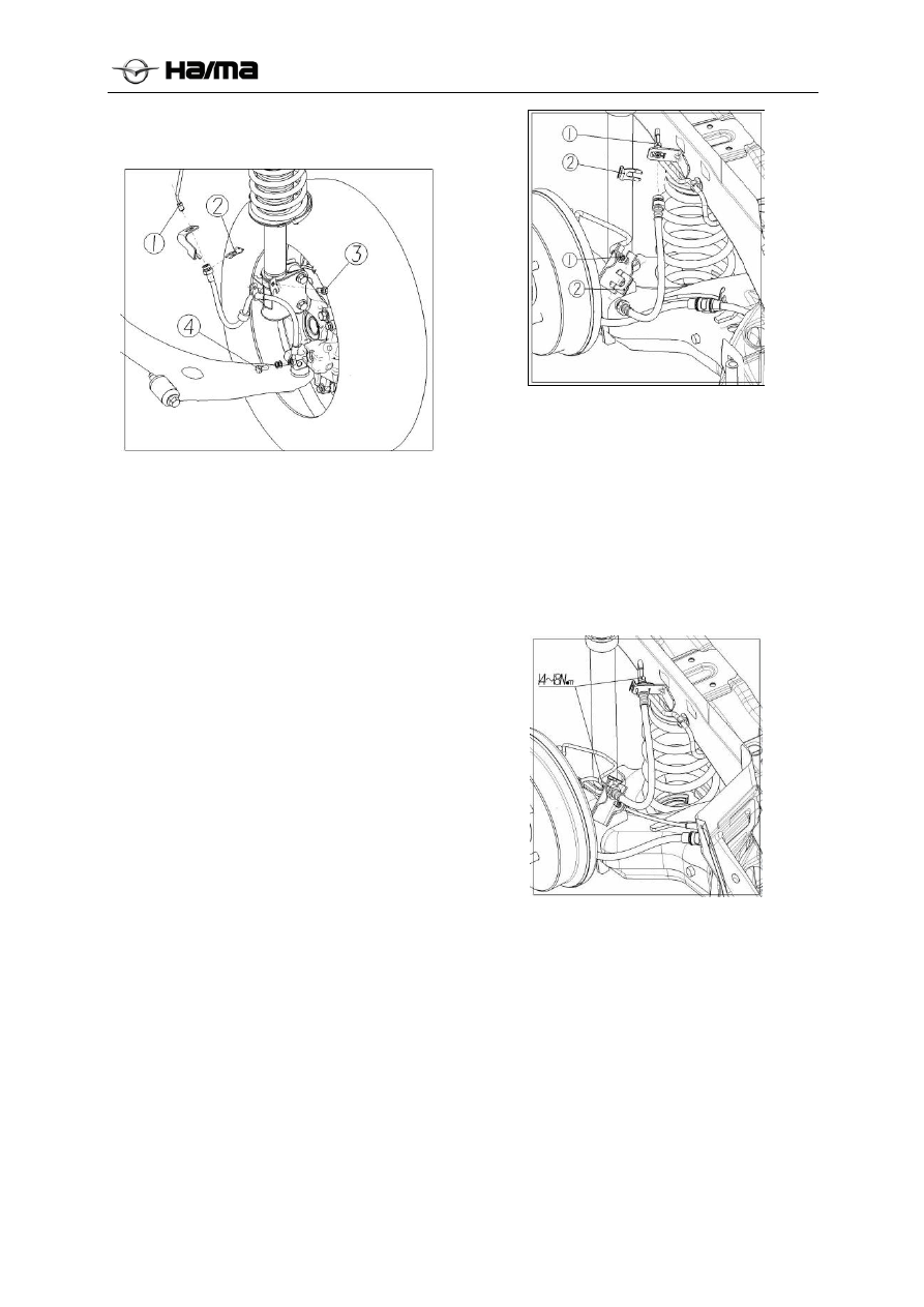
 

Rear brake hose 

Removal procedures: 

  Remove the wheel, 

  Remove the brake hose. 

  Loosen the connector connected to brake pipe 

  Remove the snap spring ②. 

  Block the opening of brake pipe, and avoid 

the loss and pollution of brake fluid. 


Installation procedures: 

1.  Connect the brake hose to the pipe. 

Tightening torque: 14 to 18N·m (12 Ib-ft). 

2.  Install the snap spring. 

Important: please apply only the recommended 

brake fluid. 

3.  Exhaust the brake system. Refer to manual 

exhaustion in this chapter. 

4.  Confirm whether the brake system is leaked. 

5.  Install the wheel. 

-------------------------------------------------------------------------------------------------------------------------------------------------------------


Brake system 2F-9 


Fig.1 


Fig.2 


Fig.3


Brake lamp switch 

Removal procedures: 

1.  Disconnect the negative cable of battery. 

2.  Remove the brake lamp switch. 

  Pull down the plug ①. 

  Turn and take down the brake lamp switch ②. 


Installation procedures: 

1.  Install the brake lamp switch. 

2. Connect 

the 

plug. 

3.  Connect the negative cable of battery. 

Important: after installing the brake lamp switch, 
be sure to pull the tie rod fully. 


Brake pedal 

Removal procedures: 

1.  Remove the brake lamp switch. 

2.  Pull out the split pin  ,

 take down the pin 

shaft ,

 and disconnect the connection of 

vacuum booster and brake pedal. 

3. Remove 

the 

bolt 

4.  Remove the lock nut, and take down the pedal 

assembly. 

5.  Removal of pedal assembly (see Fig.2) 

Loosen the lock nut  ,

 and pull out the pin shaft 

Take down the pedal arm  ,

 and pull out the 

fixing shaft sleeves ④ and ⑤. 

Take down the brake lamp lower limit cushion ⑥. 

Take down the brake pedal liner ⑦. 


Assembling procedures: 

1.  Install the pedal liner ⑦ and brake lamp 

lower limit cushion ⑥. 

2.  Install the fixing shaft sleeves  ④ and ⑤, 

pedal arm ③ and pin shaft ②. 

3.  Tighten the lock nut ①. 

Tightening torque: 22Nm(13 IB-ft). 

4.  Connect the vacuum booster and brake pedal. 

5.  Install the brake lamp switch. 

-------------------------------------------------------------------------------------------------------------------------------------------------------------


Brake system 2F-10 


Specifications 

General parameters 


Item mm 


Front brake 

Diameter of brake disc 

Thickness of brake disc  

Valid thickness of disc 

φ256 

24 
22 


Diameter of caliper cylinder 

φ54  

Rear-drum brake 

Specification 

Φ203×36. 5 


wheel cylinder diameter 

Φ19. 05/ 

Φ20. 64(proportional valve) 


Inner diameter of brake drum 

Φ203  

Rear-disc brake 

Diameter of brake disc 

φ250  

Thickness of brake disc 

10 


Valid thickness of disc 


caliper cylinder diameter 

φ34  

Vacuum booster with brake master cylinder assembly 

Assist rate 


diameter of master cylinder 

20.64 


Stroke of master cylinder 

18+18 


Brake pedal 

free stroke 

Valid stroke 

6-10 

120 


Type DOT-3 

brake fluid 

Capacity 300ml±20ml 

Tightening torque specifications of fasteners 

Application 

N·m 

Install the brake oil pipe at the joint of 
brake oil pipe. 

14 to 18 

Mounting bolt of front brake hose and 
caliper 

22 to 30  

Connecting bolt of brake pedal and pedal 
support 

19 to 25 

brake hose support tightening bolt 

8 to 14 

Connecting bolt of wheel speed sensor 
support 

8 to 14 

ABS/ESP/proportional valve support 
mounting bolt 

20 to 24 

-------------------------------------------------------------------------------------------------------------------------------------------------------------


Brake system 2F-11 


Circuit diagram 


Circuit diagram of brake warning lamp 


Battery 

ABS control unit 

Brake switch

High-mounted brake lamp 

Left brake lamp

Right brake lamp

-------------------------------------------------------------------------------------------------------------------------------------------------------------


Brake system 2F-12 


Repair of parts 

Brake master cylinder with oil cup 

General and operation 

Brake master cylinder 

The brake master cylinder is designed as per the 
shunt of system. The braking pressure of right 
front wheel brake and left rear wheel brake is 
supplied by the first chamber, and that of left front 
wheel brake and right rear wheel brake is supplied 
by the second chamber. 

Note

  During the replacement of master cylinder, 

replace the master cylinder assembly. If the 
hydraulic parts are removed or separated, the 
fluid of all or a part of brake systems must be 
drained.  

  The torque shall be achieved on the dry and 

non-lubricated fastener. 

  All the operations must be performed on clean 

platform to avoid all the mineral oils. 

Liquid level sensor 

Liquid level sensor is stuck to the liquid reservoir. 
When the brake fluid is below the liquid level line, 
this sensor activates the brake lamp. When the 
level of brake fluid becomes normal, the brake 
lamp will go out. 

Diagnostic references and procedures 


Check of brake fluid level 

1.  Check the liquid level. 

2.  If the liquid level is below MIN line, add in 

the brake fluid up to MAX. 

Brake master cylinder with brake fluid 
reservoir assembly 


Removal procedures: 

1.  Remove the brake fluid reservoir. 

  Pull out the brake fluid level alarm switch ① 

and clutch oil inlet hose ②. 

  Block the clutch oil outlet; 

  Take down the fixing screw rod ③ with a 

cross screwdriver; 

  Pull out brake fluid reservoir violently. 

2.  Remove the master cylinder. 

  Loosen the brake oil pipe joint   ;


Block the opening of master cylinder to avoid the 
outflow and pollution of brake fluid; 

  Remove the master cylinder connected to 

vacuum booster  ;


Note: the brake fluid will damage the paint. If the 
fluid overflows to the paint surface, flush it 
immediately with cold water. 

Installation procedures 

Note: apply only the specified brake fluid. 

1.  Install master cylinder assembly with a nut. 

Tightening torque: 16N·m. 

2.  Connect the fluid reservoir and brake master 

cylinder. 

3.  Connect the brake pipe and master cylinder. 

Tightening torque: 17N·m. 

4.  Exhaust the brake system. 

-------------------------------------------------------------------------------------------------------------------------------------------------------------


Brake system 2F-13 


Specifications 

General requirements 

Application Unit Value 

Master 

cylinder 

Type -  Tandem 


Hole 

diameter 

mm(in) 20.64(0.81)

Tightening torque specifications of fasteners 

Application N·m 

Fluid reservoir mounting screw  

10 

Master cylinder mounting nut 

22 

Connection of brake oil pipe 
and master cylinder 

17 

Connection of brake oil pipe 
and proportional valve 

17 

Brake oil pipe and rear wheel 
cylinder 

17 

Connection of brake oil pipe 
and front brake caliper 

17 

Vacuum booster 

Check of vacuum booster 

Check of vacuum booster functions(simple 
methods) 

Note

  Replace the vacuum booster if necessary. 

Step 1 

1.  Stop the engine, and step down the brake 

pedal several times. 

2.  Keep stepping down the brake pedal, and start 

the engine. 

3.  If the pedal moves down slightly immediately 

after starting the engine, it indicates that the 
vacuum booster is running. 

Step 2 

1.  Start the engine. 

2.  After running the engine for 1 or 2 minutes, 

stop the engine. 

3.  Step down the brake pedal with a common 

force. 

4.  If the first pedal stroke is long and the 

following stroke of stepped pedal becomes 
shortened, it indicates that the surface vacuum 
booster pump is running. 

Note:  

In case of finding out any problem, check the 
check valve and vacuum hose for damages, check 
their installation, repair and recheck them if 
necessary. 

Step 3 

1.  Start the engine. 

2.  Step down the brake pedal with a common 

force. 

3.  Keep the brake pedal in stepped position, and 

stop the engine. 

4.  Keep the brake pedal in stepped position for 

about 30s. 

5.  If the height of brake pedal is unchanged, it 

indicates that the vacuum booster is running. 

Check of vacuum booster functions (check them 
with a measuring instrument) 

1.  As shown in the figure, separately connect 

SST, vacuum gauge and pedal pressure 
detector. 

Note

  Adopt a special instrument and pedal pressure 

detector. Bleed the air out of SST at 
instrument A. 


2.  After bleeding the air out of SST, check it as 

per the following steps. 

Check of vacuum 

Leakage and non-load 

1.  Start the engine. 

2.  When the reading of vacuum gauge reaches 

66.7kPa {500mmHg}, stop the engine. 

3.  Close the vacuum gauge for15s. If the 

vacuum pressure shows 63.3-66.7kPa {475-
500mmHg}, it indicates the normal operation 
of vacuum booster. 

Loading conditions 

1.  Start the engine. 

Pedal pressure gauge

Vacuum gauge 

-------------------------------------------------------------------------------------------------------------------------------------------------------------


Brake system 2F-14 


2.  Step down the brake pedal with a force of 

196N {20kgf}. 

3.  Keep stepping down the brake pedal. When 

the reading of vacuum gauge is up to 66.7kPa 
{500mmHg}, stop the engine. 

4.  Observe the vacuum gauge for 15s. If the 

vacuum pressure indicates 63.3-66.7kPa 
{475-500mmHg}, it indicates the normal 
operation of vacuum booster. 

Check of hydraulic system 

1.  Stop the engine (vacuum pressure of 

0kPa{0mmHg}. If the pressure of fluid is 
within the specified range at this time, it 
indicates the normal operation of vacuum 
booster. 

3.  Start the engine. When its vacuum pressure 

reaches 66. 7kPa{500mmHg}, step down the 
brake pedal. 

  If the pressure of fluid is within the specified 

range at this time, it indicates the normal 
operation of brake device. 


Pedal pressure 

Fluid pressure 

196N{20kgf} 790kPa{8kgf/cm

2

}min 


 Pedal 

pressure 

Fluid pressure 

MTX

7,100kPa{72kgf/cm

2

}min

ATX

196N 
{20kgf} 

8,820kPa{90kgf/cm

2

}min


Repair instructions 


Vacuum hose and check valve:


Installation procedures 

I) Vacuum 

hose 

1. Loosen③ and ⑥ with calipers or hoop special 

tool, pull the hoses separately out of engine 
vacuum suction inlet and non-return valve 
joint; 

2.  Loosen the connecting bolt ⑤ with a wrench; 

3.  Take down the vacuum hose.  

II) Non-return 

valve. 

1. Loosen 

 and pull out the vacuum hose ④ 

with calipers or special tool; 

2.  Pull the non-return valve from the booster 

housing violently. 


Vacuum 
suction port 
of engine

-------------------------------------------------------------------------------------------------------------------------------------------------------------


Brake system 2F-15 


Vacuum booster assembly 

Removal procedures: 

1. 

First remove the air filter, 
ABS/ESP/proportional valve, support and 
relevant pipes; 

1.  Loosen the hoop, and pull out the vacuum 

power-assisting hose ⑥ and clutch oil inlet 
hose ④ with calipers; 

2.  Loosen the oil pipe connector connected to 

brake master cylinder, and block the oil outlet 
of master cylinder with a drain plug; 

3.  Pull out the split pin  ,

 take down the pin 

shaft ,

 and remove the nut ③ with a tool; 

4.  Take down the vacuum booster with master 

cylinder assembly.  

Installation procedures: 

1.  After connecting “Booster assembly-body 

inner plate-brake pedal” mounting hole, 
tighten it with lock nut, and the tightening 
torque of nut is 22 N·m; 

2.  After aligning the booster pushrod fork to the 

connecting hole of pedal arm, insert the pin 
shaft, and lock it with split pin (Install the 
vacuum booster with new split pin, U clamp 
pin and nut); 

3.  Connect the vacuum power-assisting hose and 

clutch oil inlet hose to the vacuum booster. 

4.  Connect the brake pipe and brake master 

cylinder, and tighten the oil pipe joint up to 
17N·m. 

Specifications 

Requirements for tightening torque 

Application N·m 

vacuum booster and front 
boarding mounting nut 

22 

master cylinder mounting nut 

17 

Front and rear brakes 

General and operation  

Brake caliper assembly 

This brake caliper is a single-cylinder one installed 
on the steering knuckle with two bolts. The 
hydraulic force produced by brake pedal is 
converted into braking force. This braking force 
equally acts on the piston and bottom of caliper 
chamber to make the piston move out and brake 
caliper slide in, thus an action to clamp the brake 
disc is produced, which makes the brake liner affix 
the brake disc, and produces a frictional force to 
stop the vehicle. 

-------------------------------------------------------------------------------------------------------------------------------------------------------------


Brake system 2F-16 


Note:  

During the replacement of brake caliper, please 
replace all the components. 

Lubricate the rubber parts with clean brake fluid 
for easier assembling. 

Don’t apply the lubricated compressed air to avoid 
the damages of rubber parts. 

Once the hydraulic elements are removed or 
separated, it’s required to exhaust the brake system. 

The brake liner of front brake assembly must be 
replaced in sets. 

The tightening torque is only applicable for dry or 
unlubricated fasteners. 

Repair them with clean or unpolluted wrench. 

Return clearance 

When the hydraulic pressure acts on the piston, the 
piston moves to left. At this time, the seal ring 
produces a large pressure to the piston, so it moves 
with the piston. However, the part of seal ring is 
fixed in the ring groove of brake caliper as shown 
in the figure. When the piston moves to left, the 
seal ring will be torsioned and deformed. 

After the hydraulic pressure is released, the elastic 
force stored in the seal ring makes the piston move 
to right and return to its initial position. When the 
piston moves, the brake liner will move with it, 
and the clearance between brake disc and liner will 
be gradually increased. 

After the friction block is worn, the clearance 
between the brake disc and friction block will be 
increased, and the piston stroke will be also 
increased. The seal ring has a certain deformation, 
but after its deformation exceeds the certain value, 
the seal ring will move the groove of inner end of 
cylinder body, and the elastic deformation of seal 
ring will have the specified limit. 

After the clearance is increased, the piston is 
required to move a more distance to eliminate the 

clearance. When the piston returns, its return 
stroke keeps unchanged, and the seal ring will also 
return to its initial shape, so the clearance between 
the brake disc and friction block will keep its 
initial state unchanged. 


Check of front-disc brake 

Hints for brake judder repairs  

The brake judder problems have the following 
three features: 

1.  Vibration of steering wheel: this feature is 

the most obvious when it’s braked at 100 to 
140 km/h {62 to 87 mph} if the steering 
wheel vibrates in its rotation direction; 

2.  Vibration of floor: the vehicle body shakes 

forward and back, its shaking level is not 
influenced by the vehicle speed; 

3.  Vibration of brake pedal: an impulse force 

trys to push the brake liner, and this impulse 
is transmitted to the brake pedal during the 
braking operation. 

The following are several main reasons to make 
the brake shake: 

1.  Excessive jumps of brake disc, the swing 

thickness from one side to other side is 
uneven: 

At the place 10 mm {0.39in} away from the edge 
of brake disc, if its jump exceeds 0.05mm {0.002 
in}, it indicates that the uneven wears of disc are 
caused by uneven contact of liner and disc. If its 
jump is below 0.05mm {0.002in}, it indicates that 
no uneven wears occur. 

2. 

Thermal deformation of disc:  

Repeated violent braking operations can make the 
local temperature of disc rise up to about 
1,000 {1

,832ºF}, thus it will lead to the 

deformation of disc. 

Piston 

Brake disc 

Friction block 

1. Piston 
2. Piston seal ring 
3. Friction block 
a.Clearance 

-------------------------------------------------------------------------------------------------------------------------------------------------------------


Brake system 2F-17 


3.  Due to the changes of corroded disc 

thickness and friction coefficient: 

If the vehicle parks in wet environment for a long 
time, the friction surface of disc will be corroded, 

its uneven corrosion thickness is sometimes like 
corrugations, its friction coefficient will be 
changed and produce a reaction force. 

Procedures for check and repair 


Check of transverse jump 

1.  Tighten the hub nut diagonally, and ensure 

the correct installation of disc and hub, or 
insert the washer between the hub bolt and 
hub nut. 

The thickness of washer is 10mm {0.39 in} and its 

inner diameter is over 12mm{0.47 in}. 

2.  After tightening all the hub nuts up to the 

same torque, place a dial indicator on the 
friction surface of brake disc in the position 
about 10mm{0.39in}away from the edge of 
disc. 

3.  Turn the brake disc once and measure its 

transverse jump. 

Its jump limit: 0. 05mm{0. 002 in}. 


Check of its thickness changes 

1.  Clean the friction surface of brake disc and 

brake liner with a brake cleaner. 

2.  Measure the thickness of each point shown in 

the figure with a caliper dial indicator. 

3.  Deduct the minimum value with the measured 

maximum value. If the result can’t meet the 
requirements, machine the brake disc with a 
grinding tool. 

Its thickness change limit: 0.015 mm {0.0005 in} 

Warning: 

• Don’t exceed the minimum thickness of brake 
disc. 

Certify the customer0’s 

Peform the transverse jump test. (refer 
to the transverse jump test)

Above 0.05mm {0.002in} 

Below 0.05mm 

{0.002in} 

Below 

0.05mm 

{0.002in}

Appear 

Disappear 

Confirm whether the 
brake shakes

Above 0.015mm {0.0005in} 

Below 0.015mm {0.0005in} 

Above 

0.05mm 

{0.002in}

Confirm remove the disc, install it 
in other phase position, and re-
perform the transverse jump test. 
Whether the brake shakes 

Perform the thickness change 
test (see below) 

Certify the repair conditions. 

Machine the disc with an on-
board grinder

Tighten all the hub nuts up to the 
same torque to fix the brake disc, 
and measure its transverse jump. 

Grind with an on-board grinder (below 
0.015mm{0.0005in}). 

Completion of work. 

-------------------------------------------------------------------------------------------------------------------------------------------------------------


Brake system 2F-18 


Thickness check of front or rear brake disc 

1.  Measure the thickness of brake disc. 

Caution: 

If the brake disc is removed from the vehicle for 
machining, it may cause its excessive jump. 
Therefore, it’s required to be machined when the 
brake disc is installed on the vehicle. Minimum 
thickness: front disc: 22mm {0. 87 in}. Adopt its 
minimum thickness machined on the vehicle: 22. 8 
{0. 90in} 

2.  If the thickness of brake disc is not within the 

technical requirements, replace the brake disc. 

Warning: 

 

Don’t exceed the minimum thickness of 

brake disc. 


Check of brake liner thickness 

1.  Jack up the front of vehicle, and support it 

with a safety support. 

2.  Remove the wheel. 

3.  Check the residual thickness of liner, and 

replace the sets of liners. Provided the 
thickness of one side liner of left and right 
wheels is equal to or below its minimum 
thickness, it’s required to replace left and 
right liners at the same time. Thickness of 
liner: minimum value 2. 0mm { 0. 08in}. 

4.  If the thickness of any side of left or right 

wheel is below or equal to its minimum 
thickness, replace the brake shoes from its 
both sides. 

Removal and installation of Front-disc 
brake 

1.  For its removal and installation, refer to the 

figure. 

2.  After installing it, step the brake pedal several 

times, and turn the wheel by hands to confirm 
the existence of brake drag. 

Table I: List of supply-level parts for front steering 
knuckle with brake assembly 


Table 

II: Removal of front-disc brake assembly


Caliper support bolt 

Front brake caliper assembly(left/right) 

3 Front 

brake 

disc 

Front outer friction plate 

Front inner friction plate (left/right) 

Steering knuckle assembly(left/right) 


1

Brake hose 

2

Caliper support bolt 

3

Caliper body 

4

Shaft pin bolt 

5

Guide pin rubber sleeve 

6

Guide pin 

7

Carrying support 

8

Inner and outer friction plate assembly 

9

Brake disc 


Front steering knuckle with brake assembly

Removal of front-
disc brake assembly

-------------------------------------------------------------------------------------------------------------------------------------------------------------


Brake system 2F-19 


Keypoints for removing the brake disc 

1.  Before removing it, make the marks on the 

hub bolt and brake disc for the references of 
installation.  


Keypoints for installing the brake disc 

1.  Remove any rust or dust from the contact 

surface of brake disc and hub. 

2.  Assemble the brake disc by aligning to the 

mark before removing it. 


Keypoints for installing the brake liner 

1.  Push the piston to bottom with SST. 

2.  Install the brake liner. 


Replacement of front brake liner 

1.  Remove it in the sequence shown in the 

table. 

2.  Install it in the reverse sequence of removal.

1 Bolt 

Inner and outer friction plates 

3 Support 

assembly 

4 Guide 

pin 

Guide pin dust cover 

6 brake 

caliper 

Disassembly and assembling of front brake 
caliper 

1.  Disassemble it in the sequence shown in the 

table. 

2.  Assemble it in the reverse sequence of 

removal. 

Dustproof seal ring 

Piston(refer to keypoints for 
disassembling P piston) 

Piston seal ring (refer to keypoints for 
disassembling P piston seal ring) 

Bleed screw cover 

5 Bleed 

screw 

6 brake 

caliper 

body 


Mark 

Wood 
board 

-------------------------------------------------------------------------------------------------------------------------------------------------------------


Brake system 2F-20 


Keypoints for disassembling the piston 

Note

 While blowing the compressed air into brake 
caliper, blow it slowly to avoid the sudden jump 
of piston. 

Place SST inside the brake caliper, blow the 
compressed air from the hole into brake caliper, 
to make the piston push into the brake caliper. 


Check of rear-drum brake 


Keypoints for disassembling the piston seal 
ring 

Take the brake caliper out of piston seal ring with 
SST. 


Thickness check of brake shoe friction plate 

1. Remove 

brake 

drum. 

2.  Check the thickness of residual friction 

plates. Provided the thickness of any of left 
and right friction plates is equal to below its 
minimum thickness, replace left and right 
brake shoes at the same time. 

Thickness of friction plate 

Its minimum value of 1.0 mm {0.04 in} 


Check of brake drum 

1.  Measure the inner diameter of brake drum. 

Maximum value of inner diameter 

204 mm {8. 03 in} 


  2.  Check the inner sides of brake drum for 

unflat scratches or abnormal wears. 

3.  If necessary, repair or replace the brake 

drum. 

4.  Check whether the contact of drum and 

brake shoe is good when repairing or 
replacing the brake drum. 

-------------------------------------------------------------------------------------------------------------------------------------------------------------


Brake system 2F-21 


Removal and installation of rear-drum 
brake 

1.  For its removal and installation, see the 

figure below. 


1 Wheel 

nut 

2 Wheel 

3 Countersunk 

screw 

4 Brake 

drum 

Wheel speed sensor fixing bolt 

Oil pipe joint connected to wheel 
cylinder 

Brake fixing bolt 

8 Hub 

bearing 

unit 

9 Parking 

cable 

10 Brake 

subassembly 

2.  After installing it, adjust its brake clearance 

and apply the following work. 

(1)  Step the brake pedal several times, and then 

confirm no brake drag. 

(2)  Check the clearance between the pedal and 

floor. 

(3  Check the stroke of parking brake handle. 


Disassembled components of rear-drum brake 

Rear-drum brake subassembly(left or 
right) 

2 Hexagon 

bolt 

3 Spring 

washer 

Bottom plate assembly(left or right) 

Parking wheel cylinder assembly 

Parking brake shoe assembly(left or 
right) 

Adjusting screw rod assembly 

Upper tension spring 

9 Pressure 

spring 

10

Clamping pin 

11

Sight glass plug 

12

Brake shoe assembly 

13

Lower tension spring 

14

Shifting plate 

15

Pressure spring cap 

16

Adjusting spring 

17

Rear hub bearing unit 

18

Brake drum 

19

Countersunk screw 


Removal of rear-drum brake

Components of rear-drum brake

-------------------------------------------------------------------------------------------------------------------------------------------------------------


Brake system 2F-22 


Keypoints for removing the brake drum 

Before removing the brake drum, make the marks 
on the bolt and brake drum for references of 
installation.  

Keypoints for installing the brake drum 

1.  Remove the rust and dust from the contact 

surface of drum brake. 

2.  Align the mark made before the removal, and 

assemble the brake drum. 

3.  After installing the brake drum, adjust the 

clearance of brake shoe as per the following 
steps. 

(1)  Turn the regulator on adjusting support to 

make its length L: 2mm-3 mm {0.079 in - 
0.11in}. 

(2)  Remove the rust and dust from the contact 

surface of drum brake. 

(3)  Align the mark made before the removal, and 

assemble the brake drum. 

(4)  Step the brake pedal 30 times to activate the 

automatic adjuster. 

Disassembly and assembly of wheel cylinder 

1 Dust 

cover 

Wheel cylinder piston 

Wheel cylinder rubber cup 

4 Wheel 

cylinderspring 

Bleed screw cover 

6 Bleed 

screw 

Wheel cylinder body 

Note 

  In case of finding out any problem, replace the 

wheel cylinder assembly. 

1.  Assemble it in the sequence shown in the table.

2.  Assemble it in the reverse sequence of 

removal. 


Mark 

-------------------------------------------------------------------------------------------------------------------------------------------------------------


Brake system 2F-23 


Check of rear-disc brake 

Hints for repair of brake tremor (refer to 
front-disc brake) 

Thickness check of rear brake disc 

1.  Measure the thickness of brake disc. 

Note

If the brake disc is removed from the vehicle for 
machining, it may cause its excessive jump. 
Therefore, it’s required to machine during the 
installation of brake disc on the vehicle. 


1 Wheel 

nut 

Minimum thickness: rear disc: 8mm {0.31in} 
Adopt the minimum thickness machined on the 
vehicle: 8.8 {0.35in} 

2. If the thickness of brake disc is not within the 
technical requirements, replace the brake disc. 

Warning: 

  Don’t exceed the minimum thickness of 

brake disc.  

Thickness check of brake liner 

1.  Jack up the front of vehicle with a jack, and 

tie it firmly with a safety support. 

2.  Remove the wheel. 

3.  Check the residual thickness of liner, and 

replace the liner in sets. Provided the 
thickness of any block of left and right 
wheels is below or equal to its minimum 
thickness, it’s required to replace left and 
right liners at the same time. 

Minimum thickness of rear liner: 2.0 mm {0.8in}

4.  If the thickness of any side of left and right 

wheels is below or equal to its minimum 
thickness, replace both brake shoes in sets. 


-------------------------------------------------------------------------------------------------------------------------------------------------------------


Content      ..     3      4      5      6     ..