Lancia VOYAGER. Service Manual - part 15
 

  Index      Manuals     Lancia VOYAGER. Service Manual


Search            copyright infringement  


Content      ..     13      14      15      16     ..


Lancia VOYAGER. Service Manual - part 15


KEY IGNITION PARK
INTERLOCK

This vehicle is equipped with a Key
Ignition Park Interlock which re-
quires the transmission to be in PARK
before the ignition switch can be
turned to the LOCK position. The key
fob can only be removed from the
ignition when the ignition is in the
LOCK position, and the transmission
is locked in PARK whenever the igni-
tion switch is in the LOCK position.

NOTE: If a malfunction occurs,
the system will trap the key fob in
the ignition switch to warn you
that this safety feature is inoper-
able. The engine can be started
and stopped but the key fob cannot
be removed until you obtain ser-
vice.

BRAKE/TRANSMISSION
SHIFT INTERLOCK
SYSTEM

This vehicle is equipped with a Brake
Transmission Shift Interlock System
(BTSI) that holds the shift lever in
PARK unless the brakes are applied.

To shift the transmission out of PARK,
the ignition switch must be turned to
the ON/RUN position (engine run-
ning or not) and the brake pedal must
be pressed.

SIX-SPEED AUTOMATIC
TRANSMISSION

The transmission gear position dis-
play (located in the instrument clus-
ter) indicates the transmission gear
range. You must press the brake pedal
to move the shift lever out of PARK
(Refer to Brake/Transmission Shift
Interlock System in this section). To
drive, move the shift lever from PARK
or NEUTRAL to the DRIVE position.

The electronically-controlled trans-
mission provides a precise shift sched-
ule. The transmission electronics are
self-calibrating; therefore, the first
few shifts on a new vehicle may be
somewhat abrupt. This is a normal
condition, and precision shifts will de-
velop within a few hundred kilome-
ters.

Only shift from DRIVE to PARK or
REVERSE

when

the accelerator

pedal is released and the vehicle is
stopped. Be sure to keep your foot on
the brake pedal when shifting be-
tween these gears.

The transmission shift lever has only
PARK, REVERSE, NEUTRAL, and
DRIVE shift positions. Manual down-
shifts can be made using the Elec-
tronic Range Select (ERS) shift con-
trol (described later in this section).
Moving the shift lever to the left or
right (–/ +) while in the DRIVE posi-
tion will select the highest available
transmission gear, and will display
that gear in the instrument cluster as
6, 5, 4, 3, 2, 1.

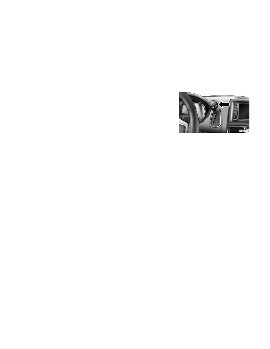
Shift Lever

237

-------------------------------------------------------------------------------------------------------------------------------------------------------------

GEAR RANGES

DO NOT race the engine when shift-
ing from PARK or NEUTRAL into
another gear range.

NOTE: After selecting any gear
range, wait a moment to allow the
selected gear to engage before ac-
celerating. This is especially im-
portant when the engine is cold.

PARK (P)

This range supplements the parking
brake by locking the transmission.
The engine can be started in this
range. Never attempt to use PARK
while the vehicle is in motion. Apply
the parking brake when leaving the
vehicle in this range.

When parking on a level surface, you
may shift the transmission into PARK
first, and then apply the parking
brake.

When parking on a hill, apply the
parking brake before shifting the
transmission to PARK, otherwise the
load on the transmission locking
mechanism may make it difficult to
move the shift lever out of PARK. As

an added precaution, turn the front
wheels toward the curb on a downhill
grade, and away from the curb on an
uphill grade.

WARNING!

• Never use the PARK position as a

substitute for the parking brake.
Always apply the parking brake
fully when parked to guard
against vehicle movement and
possible injury or damage.

• Your vehicle could move and in-

jure you and others if it is not
completely in PARK. Check by
trying to move the shift lever out
of PARK with the brake pedal
released. Make sure the transmis-
sion is in PARK before leaving the
vehicle.

(Continued)

WARNING!

(Continued)

• It is dangerous to shift out of

PARK or NEUTRAL if the engine
speed is higher than idle speed. If
your foot is not firmly pressing
the brake pedal, the vehicle could
accelerate quickly forward or in
reverse. You could lose control of
the vehicle and hit someone or
something. Only shift into gear
when the engine is idling nor-
mally and your foot is firmly
pressing the brake pedal.

• Unintended movement of a ve-

hicle could injure those in or near
the vehicle. As with all vehicles,
you should never exit a vehicle
while the engine is running. Be-
fore exiting a vehicle, always ap-
ply the parking brake, shift the
transmission into PARK, turn the
engine OFF, and remove the key
fob. When the ignition is in the
LOCK position, the transmission
is locked in PARK, securing the
vehicle against unwanted move-
ment.

(Continued)

238

-------------------------------------------------------------------------------------------------------------------------------------------------------------

WARNING!

(Continued)

• When leaving the vehicle, always

remove the key fob and lock your
vehicle.

• Never leave children alone in a

vehicle, or with access to an un-
locked vehicle.

• Allowing children to be in a ve-

hicle unattended is dangerous for
a number of reasons. A child or
others could be seriously or fa-
tally injured. Children should be
warned not to touch the parking
brake, brake pedal or the shift
lever.

• Do not leave the key fob in or near

the vehicle, (or in a location ac-
cessible to children), and do not
leave the ignition (in a vehicle
equipped with Keyless Enter-N-
Go™) in the ACC or ON/RUN
position A child could operate
power windows, other controls, or
move the vehicle.

CAUTION!

• Before moving the shift lever out

of PARK, you must place the ig-
nition from the LOCK/OFF posi-
tion to the ON/RUN position, and
also press the brake pedal. Other-
wise, damage to the shift lever
could result.

• DO NOT race the engine when

shifting from PARK or NEU-
TRAL into another gear range, as
this can damage the drivetrain.

The following indicators should be
used to ensure that you have engaged
the transmission into the PARK posi-
tion:

• When shifting into PARK, firmly

move the shift lever all the way
forward and to the left until it stops
and is fully seated.

• Look at the transmission gear posi-

tion display and verify that it indi-
cates the PARK position.

• With brake pedal released, verify

that the shift lever will not move out
of PARK.

REVERSE (R)

This range is for moving the vehicle
backward. Shift into REVERSE only
after the vehicle has come to a com-
plete stop.

NEUTRAL (N)

Use this range when the vehicle is
standing for prolonged periods with
the engine running. The engine may
be started in this range. Apply the
parking brake and shift the transmis-
sion into PARK if you must leave the
vehicle.

WARNING!

Do not coast in NEUTRAL and
never turn off the ignition to coast
down a hill. These are unsafe prac-
tices that limit your response to
changing traffic or road conditions.
You might lose control of the ve-
hicle and have a collision.

239

-------------------------------------------------------------------------------------------------------------------------------------------------------------

CAUTION!

Towing the vehicle, coasting, or
driving for any other reason with
the transmission in NEUTRAL can
cause severe transmission damage.
Refer to “Recreational Towing” in
“Starting And Operating” and
“Towing A Disabled Vehicle” in
“What To Do In Emergencies” for
further information.

DRIVE (D)

This range should be used for most
city and highway driving. It provides
the smoothest upshifts and down-
shifts, and the best fuel economy. The
transmission automatically upshifts
through all forward gears. The
DRIVE position provides optimum
driving characteristics under all nor-
mal operating conditions.

When frequent transmission shifting
occurs (such as when operating the
vehicle under heavy loading condi-
tions, in hilly terrain, traveling into
strong head winds, or while towing
heavy trailers), use the Electronic

Range Select (ERS) shift control (de-
scribed below) to select a lower gear
range. Under these conditions, using a
lower gear range will improve perfor-
mance and extend transmission life
by reducing excessive shifting and
heat buildup.

During cold temperatures, transmis-
sion operation may be modified de-
pending on engine and transmission
temperature as well as vehicle speed.
This feature improves warm up time
of the engine and transmission to
achieve maximum efficiency. Engage-
ment of the torque converter clutch is
inhibited until the transmission fluid
is warm (refer to the “Note” under
“Torque Converter Clutch” in this
section). During extremely cold tem-
peratures (-27°C or below), operation
may briefly be limited to third gear
only. Normal operation will resume
once the transmission temperature
has risen to a suitable level.

Transmission Limp Home Mode

Transmission function is monitored
electronically for abnormal condi-
tions. If a condition is detected that

could result in transmission damage,
Transmission Limp Home Mode is ac-
tivated. In this mode, the transmis-
sion remains in third gear regardless
of which forward gear is selected.
PARK, REVERSE, and NEUTRAL
will continue to operate. The Mal-
function Indicator Light (MIL) may
be illuminated. Limp Home Mode al-
lows the vehicle to be driven to an
authorized dealer for service without
damaging the transmission.

In the event of a momentary problem,
the transmission can be reset to regain
all forward gears by performing the
following steps:

1. Stop the vehicle.

2. Shift the transmission into PARK.

3. Turn the ignition switch to the
LOCK/OFF position.

4. Wait approximately 10 seconds.

5. Restart the engine.

6. Shift into the desired gear range. If
the problem is no longer detected, the
transmission will return to normal op-
eration.

240

-------------------------------------------------------------------------------------------------------------------------------------------------------------

NOTE: Even if the transmission
can be reset, we recommend that
you visit your authorized dealer at
your

earliest

possible

conve-

nience. Your authorized dealer has
diagnostic equipment to deter-
mine if the problem could recur.

If the transmission cannot be reset,
authorized dealer service is required.

Electronic Range Select (ERS)
Operation

The Electronic Range Select (ERS)
shift control allows the driver to limit
the highest available gear when the
shift lever is in the DRIVE position.
For example, if you shift the transmis-
sion into 3 (third gear), the transmis-
sion will not shift above third gear

(except to prevent engine overspeed),
but will shift down into second and
first gears normally.

You can switch between DRIVE and
ERS mode at any vehicle speed. When
the shift lever is in the DRIVE posi-
tion, the transmission will operate au-
tomatically,

shifting

between

all

available gears. Tapping the shift le-
ver to the left (-) will activate ERS
mode, display the current gear in the
instrument cluster, and maintain that
gear as the top available gear. Once in
ERS mode, tapping the shift lever to
the left (-) or right (+) will change the
top available gear.

To exit ERS mode, simply press and
hold the shift lever to the right (+)
until “D” is once again displayed in
the instrument cluster.

WARNING!

Do not downshift for additional en-
gine braking on a slippery surface.
The drive wheels could lose their
grip and the vehicle could skid,
causing a collision or personal in-
jury.

Transmission Gear Position Display

1

2

3

4

5

6

D

Actual Gear(s) Allowed

1

1–2

1–3

1–4

1–5

1–6

1–6

NOTE: To select the proper gear
position for maximum decelera-
tion (engine braking), tap the shift
lever to the left (-) repeatedly as the
vehicle slows. The transmission
will shift to the range from which

the vehicle can best be slowed
down.

Overdrive Operation

The automatic transmission includes
an electronically controlled Overdrive
(sixth gear). The transmission will

automatically shift into Overdrive if
the following conditions are present:

• The shift lever is in the DRIVE po-

sition.

• The transmission fluid has reached

an adequate temperature.

241

-------------------------------------------------------------------------------------------------------------------------------------------------------------

• The engine coolant has reached an

adequate temperature.

• The vehicle speed is sufficiently

high.

• The driver is not heavily pressing

the accelerator.

Torque Converter Clutch

A feature designed to improve fuel
economy has been included in the au-
tomatic transmission on your vehicle.
A clutch within the torque converter
engages automatically at calibrated
speeds. This may result in a slightly
different feeling or response during
normal operation in the upper gears.
When the vehicle speed drops or dur-
ing some accelerations, the clutch au-
tomatically disengages.

NOTE: The

torque

converter

clutch will not engage until the
transmission fluid and engine
coolant are warm [usually after 2
to 5 km of driving]. Because the
engine speed is higher when the

torque converter clutch is not en-
gaged, it may seem as if the trans-
mission is not shifting into Over-
drive when cold. This is normal.
Using the Electronic Range Select
(ERS) shift control, when the
transmission is sufficiently warm,
will demonstrate that the trans-
mission is able to shift into and out
of Overdrive.

DRIVING ON SLIPPERY
SURFACES

ACCELERATION

Rapid acceleration on snow covered,
wet, or other slippery surfaces may
cause the driving wheels to pull errati-
cally to the right or left. This phenom-
enon occurs when there is a difference
in the surface traction under the front
(driving) wheels.

WARNING!

Rapid acceleration on slippery sur-
faces is dangerous. Unequal trac-
tion can cause sudden pulling of the
front wheels. You could lose control
of the vehicle and possibly have a
collision. Accelerate slowly and
carefully whenever there is likely to
be poor traction (ice, snow, wet,
mud, loose sand, etc.).

TRACTION

When driving on wet or slushy roads,
it is possible for a layer of water to
build up between the tire and road
surface. This is known as hydroplan-
ing and may cause partial or complete
loss of vehicle control and stopping
ability. To reduce this possibility, the
following precautions should be ob-
served:

1. Slow down during rainstorms or
when roads are slushy.

2. Slow down if the road has standing
water or puddles.

242

-------------------------------------------------------------------------------------------------------------------------------------------------------------

3. Replace the tires when tread wear
indicators first become visible.

4. Keep the tires properly inflated.

5. Maintain sufficient distance be-
tween your vehicle and the vehicle in
front of you to avoid a collision in a
sudden stop.

DRIVING THROUGH
WATER

Driving through water more than a
few centimeters deep will require ex-
tra caution to ensure safety and pre-
vent damage to your vehicle.

FLOWING/RISING WATER

WARNING!

Do not drive on or across a road or
path where water is flowing and/or
rising (as in storm run-off). Flow-
ing water can wear away the road
or path's surface and cause your
vehicle to sink into deeper water.
Furthermore, flowing and/or rising
water can carry your vehicle away
swiftly. Failure to follow this warn-
ing may result in injuries that are
serious or fatal to you, your passen-
gers, and others around you.

SHALLOW STANDING
WATER

Although your vehicle is capable of
driving through shallow standing wa-
ter, consider the following Caution
and Warning before doing so.

CAUTION!

• Always check the depth of the

standing water before driving
through it. Never drive through
standing water that is deeper
than the bottom of the tire rims
mounted on the vehicle.

• Determine the condition of the

road or the path that is under
water and if there are any ob-
stacles in the way before driving
through the standing water.

• Do not exceed 8 km/h when driv-

ing through standing water. This
will minimize wave effects.

(Continued)

243

-------------------------------------------------------------------------------------------------------------------------------------------------------------

CAUTION!

(Continued)

• Driving through standing water

may cause damage to your vehi-
cle’s drivetrain components. Al-
ways inspect your vehicle’s fluids
(i.e., engine oil, transmission,
axle, etc.) for signs of contamina-
tion (i.e., fluid that is milky or
foamy in appearance) after driv-
ing through standing water. Do
not continue to operate the ve-
hicle if any fluid appears con-
taminated, as this may result in
further damage. Such damage is
not covered by the New Vehicle
Limited Warranty.

• Getting water inside your vehi-

cle’s engine can cause it to lock up
and stall out, and cause serious
internal damage to the engine.
Such damage is not covered by
the New Vehicle Limited War-
ranty.

WARNING!

• Driving through standing water

limits your vehicle’s traction ca-
pabilities. Do not exceed 8 km/h
when driving through standing
water.

• Driving through standing water

limits your vehicle’s braking ca-
pabilities, which increases stop-
ping distances. Therefore, after
driving through standing water,
drive slowly and lightly press on
the brake pedal several times to
dry the brakes.

• Getting water inside your vehi-

cle’s engine can cause it to lock up
and stall out, and leave you
stranded.

• Failure to follow these warnings

may result in injuries that are se-
rious or fatal to you, your passen-
gers, and others around you.

POWER STEERING

The standard power steering system
will give you good vehicle response
and increased ease of maneuverability

in tight spaces. The system will pro-
vide mechanical steering capability if
power assist is lost.

If for some reason the power assist is
interrupted, it will still be possible to
steer your vehicle. Under these condi-
tions, you will observe a substantial
increase in steering effort, especially
at very low vehicle speeds and during
parking maneuvers.

NOTE:

• Increased noise levels at the end

of the steering wheel travel are
considered normal and do not
indicate that there is a problem
with the power steering system.

• Upon initial start-up in cold

weather, the power steering
pump may make noise for a
short amount of time. This is due
to the cold, thick fluid in the
steering

system.

This

noise

should be considered normal,
and it does not in any way dam-
age the steering system.

244

-------------------------------------------------------------------------------------------------------------------------------------------------------------

WARNING!

Continued operation with reduced
power steering assist could pose a
safety risk to yourself and others.
Service should be obtained as soon
as possible.

CAUTION!

Prolonged operation of the steering
system at the end of the steering
wheel travel will increase the steer-
ing fluid temperature and it should
be avoided when possible. Damage
to the power steering pump may
occur.

POWER STEERING FLUID
CHECK

Checking the power steering fluid
level at a defined service interval is
not required. The fluid should only be
checked if a leak is suspected, abnor-
mal noises are apparent, and/or the
system is not functioning as antici-
pated. Coordinate inspection efforts
through an authorized dealer.

CAUTION!

Do not use chemical flushes in your
power steering system as the
chemicals can damage your power
steering components. Such damage
is not covered by the New Vehicle
Limited Warranty.

WARNING!

Fluid level should be checked on a
level surface and with the engine off
to prevent injury from moving parts
and to ensure accurate fluid level
reading. Do not overfill. Use only
manufacturer's

recommended

power steering fluid.

If necessary, add fluid to restore to the
proper indicated level. With a clean
cloth, wipe any spilled fluid from all
surfaces. Refer to “Fluids, Lubri-
cants, and Genuine Parts” in “Main-
taining Your Vehicle” for further in-
formation.

PARKING BRAKE

Before leaving the vehicle, make sure
that the parking brake is fully applied
and place the shift lever in the PARK
position.

The foot operated parking brake is
positioned below the lower left corner
of the instrument panel. To apply the
park brake, firmly push the park
brake pedal fully. To release the park-
ing brake, press the park brake pedal
a second time and let your foot up as
you feel the brake disengage.

When the parking brake is applied
with the ignition switch in the ON
position, the “Brake Warning Light”
in the instrument cluster will illumi-
nate.

Parking Brake

245

-------------------------------------------------------------------------------------------------------------------------------------------------------------

NOTE:

• When the parking brake is ap-

plied and the automatic trans-
mission is placed in gear, the
“Brake Warning Light” will
flash. If vehicle speed is de-
tected, a chime will sound to
alert the driver. Fully release the
parking brake before attempting
to move the vehicle.

• This light only shows that the

parking brake is applied. It does
not show the degree of brake ap-
plication.

When parking on a hill, it is important
to turn the front wheels toward the
curb on a downhill grade and away
from the curb on an uphill grade. For
vehicles equipped with an automatic
transmission, apply the parking brake
before placing the shift lever in PARK,
otherwise the load on the transmis-
sion locking mechanism may make it
difficult to move the shift lever out of
PARK. The parking brake should al-
ways be applied whenever the driver
is not in the vehicle.

WARNING!

• Never use the PARK position as a

substitute for the parking brake.
Always apply the parking brake
fully when parked to guard
against vehicle movement and
possible injury or damage.

• When leaving the vehicle, always

remove the key fob from the igni-
tion and lock your vehicle.

• Never leave children alone in a

vehicle, or with access to an un-
locked vehicle. Allowing children
to be in a vehicle unattended is
dangerous for a number of rea-
sons. A child or others could be
seriously or fatally injured. Chil-
dren should be warned not to
touch the parking brake, brake
pedal or the shift lever.

(Continued)

WARNING!

(Continued)

• Do not leave the key fob in or near

the vehicle (or in a location acces-
sible to children), and do not
leave the ignition of a vehicle
equipped with Keyless Enter-N-
Go™ in the ACC or ON/RUN
mode. A child could operate
power windows, other controls, or
move the vehicle.

CAUTION!

If the Brake System Warning Light
remains on with the parking brake
released, a brake system malfunc-
tion is indicated. Have the brake
system serviced by an authorized
dealer immediately.

ANTI-LOCK BRAKE
SYSTEM (ABS)

The Anti-Lock Brake System (ABS)
provides increased vehicle stability
and brake performance under most
braking conditions. The system oper-
ates with a separate computer to

246

-------------------------------------------------------------------------------------------------------------------------------------------------------------

modulate hydraulic pressure to pre-
vent wheel lock-up and help avoid
skidding on slippery surfaces.

ABS is activated during braking un-
der certain road or stopping condi-
tions. ABS-inducing conditions can
include ice, snow, gravel, bumps, rail-
road tracks, loose debris, or panic
stops.

You may experience the following
when the brake system goes into anti-
lock:

• The ABS motor running (it may

continue to run for a short time
after the stop).

• A clicking sound of solenoid valves.

• Brake pedal pulsations.

• A slight drop or fall away of the

brake pedal at the end of the stop.

WARNING!

• The Anti-Lock Brake System

contains sophisticated electronic
equipment that may be suscep-
tible to interference caused by
improperly installed, or high out-
put radio transmitting equip-
ment. This interference can cause
possible loss of anti-lock braking
capability. Installation of such
equipment should be performed
by qualified professionals.

• Pumping of the Anti-Lock Brakes

will diminish their effectiveness
and may lead to a collision.
Pumping makes the stopping dis-
tance longer. Just press firmly on
your brake pedal when you need
to slow down or stop.

• The Anti-Lock Brake System

cannot prevent collisions, includ-
ing those resulting from excessive
speed in turns, following another
vehicle too closely, or hydroplan-
ing.

(Continued)

WARNING!

(Continued)

• The capabilities of an ABS-

equipped vehicle must never be
exploited in a reckless or danger-
ous manner, which could jeopar-
dize the user’s safety or the safety
of others.

• The ABS cannot prevent the

natural laws of physics from act-
ing on the vehicle, nor can it in-
crease braking or steering effi-
ciency beyond that afforded by
the condition of the vehicle
brakes and tires or the traction
afforded.

All vehicle wheels and tires must be
the same size and type, and tires must
be properly inflated to produce accu-
rate signals for the computer.

ANTI-LOCK BRAKE
WARNING LIGHT

The

“Anti-Lock

Brake

Warning Light” monitors
the anti-lock brake system.
The light will come on when

247

-------------------------------------------------------------------------------------------------------------------------------------------------------------

the ignition switch is turned to the ON
position and may stay on for as long
as four seconds.

If the “Anti-Lock Brake Warning
Light” remains on or comes on while
driving, it indicates that the anti-lock
portion of the brake system is not
functioning and that service is re-
quired. However, the conventional
brake system will continue to operate
normally if the “Brake Warning
Light” is not on.

If the “Anti-Lock Brake Warning
Light” is on, the brake system should
be serviced as soon as possible to re-
store the benefits of anti-lock brakes.
If the “Anti-Lock Brake Warning
Light” does not come on when the
ignition switch is turned to the ON
position, have the bulb repaired as
soon as possible.

If both the “Brake Warning Light”
and the “Anti-Lock Brake Warning
Light” remain on, the ABS and Elec-
tronic

Brake

Force

Distribution

(EBD) systems are not functioning.
Immediate repair to the ABS system is

required. Consult with your autho-
rized dealer service center as soon as
possible.

ELECTRONIC BRAKE
CONTROL SYSTEM (for
versions/markets, where
provided)

Your vehicle is equipped with an ad-
vanced electronic brake control sys-
tem that includes the Traction Control
System (TCS), Brake Assist System
(BAS) and Electronic Stability Con-
trol (ESC), Trailer Sway Control
(TSC), and Hill Start Assist (HSA).
These systems complement the Anti-
Lock Brake System (ABS) by opti-
mizing the vehicle braking capability
during emergency braking maneu-
vers.

TRACTION CONTROL
SYSTEM (TCS) (for
versions/markets, where
provided)

The Traction Control System (TCS)
monitors the amount of wheel spin of
each of the driven wheels. If wheel

spin is detected, brake pressure is ap-
plied to the slipping wheel(s) and en-
gine power is reduced, to provide en-
hanced acceleration and stability. A
feature of the TCS functions similarly
to a limited-slip differential, and con-
trols the wheel spin across a driven
axle. If one wheel on a driven axle is
spinning faster than the other, the sys-
tem will apply the brake of the spin-
ning wheel. This will allow more en-
gine torque to be applied to the wheel
that is not spinning. This feature re-
mains active even if the ESC is in the
“Partial Off” mode.

The “ESC Activation/Malfunction In-
dicator Light” (in the instrument
cluster) will start to flash as soon as
the tires lose traction and the wheels
begin to spin. This indicates that the
TCS is active. If the indicator light
flashes during acceleration, ease up
on the accelerator and apply as little
throttle as possible. Be sure to adapt
your speed and driving to the prevail-
ing road conditions, and do not switch
off the ESC or TCS.

248

-------------------------------------------------------------------------------------------------------------------------------------------------------------

WARNING!

• The TCS cannot prevent the

natural laws of physics from act-
ing on the vehicle, nor can it in-
crease the traction afforded.

• The TCS cannot prevent colli-

sions, including those resulting
from excessive speed in turns, or
hydroplaning.

• The capabilities of a TCS-

equipped vehicle must never be
exploited in a reckless or danger-
ous manner, which could jeopar-
dize the user's safety or the safety
of others.

BRAKE ASSIST SYSTEM
(BAS) (for versions/markets,
where provided)

The Brake Assist System (BAS) is de-
signed to optimize the vehicle’s brak-
ing capability during emergency
braking maneuvers. The system de-
tects an emergency braking situation
by sensing the rate and amount of
brake application, and then applies
optimum pressure to the brakes. This
can help reduce braking distances.

The BAS complements the ABS. Ap-
plying the brakes very quickly results
in the best BAS assistance. To receive
the benefit of the system, you must
apply continuous braking pressure
during the stopping sequence. Do not
reduce brake pedal pressure unless
braking is no longer desired. Once the
brake pedal is released, the BAS is
deactivated.

WARNING!

• The BAS cannot prevent the

natural laws of physics from act-
ing on the vehicle, nor can it in-
crease the traction afforded by
prevailing road conditions.

• The BAS cannot prevent colli-

sions, including those resulting
from excessive speed in turns,
driving on very slippery surfaces,
or hydroplaning.

• The

capabilities

of

a

BAS-

equipped vehicle must never be
exploited in a reckless or danger-
ous manner which could jeopar-
dize the user's safety or the safety
of others.

ELECTRONIC STABILITY
CONTROL (ESC)

The

Electronic

Stability

Control

(ESC) enhances directional control
and stability of the vehicle under vari-
ous driving conditions. ESC corrects
for over/under steering of the vehicle
by applying the brake of the appro-
priate wheel to assist in counteracting
the over/under steer condition. En-
gine power may also be reduced to
help the vehicle maintain the desired
path.

ESC uses sensors in the vehicle to
determine the vehicle path intended
by the driver and compares it to the
actual path of the vehicle. When the
actual path does not match the in-
tended path, ESC applies the brake of
the appropriate wheel to assist in
counteracting the oversteer or under-
steer condition.

• Oversteer - when the vehicle is

turning more than appropriate for
the steering wheel position.

249

-------------------------------------------------------------------------------------------------------------------------------------------------------------

• Understeer - when the vehicle is

turning less than appropriate for
the steering wheel position.

WARNING!

The Electronic Stability Control
System (ESC) cannot prevent the
natural laws of physics from acting
on the vehicle, nor can it increase the
traction afforded by prevailing road
conditions. ESC cannot prevent all
accidents, including those resulting
from excessive speed in turns, driv-
ing on very slippery surfaces, or hy-
droplaning. ESC also cannot prevent
accidents resulting from loss of ve-
hicle control due to inappropriate
driver input for the conditions. Only
a safe, attentive, and skillful driver
can prevent accidents. The capabili-
ties of an ESC equipped vehicle must
never be exploited in a reckless or
dangerous manner which could
jeopardize the user’s safety or the
safety of others.

ESC Operating Modes

The “ESC Off” switch is lo-
cated in the center switch
bank, next to the hazard
flasher switch.

ESC On

This mode is the normal operating
mode for ESC on two-wheel drive ve-
hicles. Whenever the vehicle is
started, the ESC system will be in this
mode. This mode should be used for
most driving situations. ESC should
only be turned off for specific reasons
as noted below.

ESC Partial Off

This mode is entered by momentarily
pressing the “ESC Off” switch.

When in the “Partial Off” mode, the
TCS portion of ESC, except for the
“limited slip” feature described in the
TCS section, has been disabled and
the “ESC Off Indicator Light” will be
illuminated. When in the “Partial
Off” mode, ESC will operate without
engine torque management. This
mode is intended to be used if the

vehicle is in deep snow, sand or gravel
conditions and more wheel spin than
ESC would normally allow is required
to gain traction. To turn ESC on
again, momentarily press the “ESC
Off” switch. This will restore the nor-
mal “ESC On” mode of operation.

NOTE: To improve the vehicle's
traction when driving with snow
chains, or starting off in deep
snow, sand or gravel, it may be
desirable to switch to the “Partial
Off” mode by pressing the “ESC
Off” switch. Once the situation re-
quiring ESC to be switched to the
“Partial Off” mode is overcome,
turn ESC back on by momentarily
pressing the “ESC Off” switch.
This may be done while the vehicle
is in motion.

WARNING!

In partial ESC mode, the engine
power reduction feature of ESC is
disabled. Therefore, enhanced ve-
hicle stability offered by the ESC
system is reduced.

250

-------------------------------------------------------------------------------------------------------------------------------------------------------------

ESC Activation/Malfunction
Indicator Light And ESC OFF
Indicator Light

The

“ESC

Activation/

Malfunction

Indicator

Light” in the instrument
cluster will come on when

the ignition switch is turned to the ON
position. It should turn off with the
engine

running.

If

the

“ESC

Activation/Malfunction

Indicator

Light” comes on continuously with the
engine running, a malfunction has
been detected in the ESC system. If this
light remains on after several ignition
cycles, and the vehicle has been driven
several kilometers at speeds greater
than 48 km/h, see your authorized
dealer as soon as possible to have the
problem diagnosed and corrected.

The “ESC Activation/Malfunction In-
dicator Light” (located in the instru-
ment cluster) starts to flash as soon as
the tires lose traction and the ESC sys-
tem

becomes

active.

The

“ESC

Activation/Malfunction

Indicator

Light” also flashes when TCS is active.

If the “ESC Activation/Malfunction In-
dicator Light” begins to flash during
acceleration, ease up on the accelerator
and apply as little throttle as possible.
Be sure to adapt your speed and driving
to the prevailing road conditions.

NOTE:

• The “ESC Activation/Malfunction

Indicator Light” and the “ESC
OFF Indicator Light” come on
momentarily each time the igni-
tion switch is turned ON.

• Each time the ignition is turned

ON, the ESC system will be ON
even

if

it

was

turned

off

previously.

• The ESC system will make buzz-

ing or clicking sounds when it is
active. This is normal; the
sounds will stop when ESC be-
comes inactive following the
maneuver that caused the ESC
activation.

The “ESC OFF Indicator
Light” indicates the Elec-
tronic

Stability

Control

(ESC) is off.

TRAILER SWAY CONTROL
(TSC)

TSC uses sensors in the vehicle to
recognize an excessively swaying
trailer and will take the appropriate
actions to attempt to stop the sway.
The system may reduce engine power
and apply the brake of the appropri-
ate wheel(s) to counteract the sway of
the trailer. TSC will become active
automatically once an excessively
swaying trailer is recognized. No
driver action is required. Note that
TSC cannot stop all trailers from
swaying. Always use caution when
towing a trailer and follow the trailer
tongue weight recommendations. Re-
fer to “Trailer Towing” in this section
for further information. When TSC is
functioning, the “ESC Activation/
Malfunction Indicator Light” will
flash, the engine power may be re-
duced and you may feel the brakes
being applied to individual wheels to
attempt to stop the trailer from sway-
ing. TSC is disabled when the ESC
system is in the “Partial Off” mode.

251

-------------------------------------------------------------------------------------------------------------------------------------------------------------

WARNING!

If TSC activates while driving, slow
the vehicle down, stop at the near-
est safe location, and adjust the
trailer load to eliminate trailer
sway.

HILL START ASSIST (HSA)

The HSA system is designed to assist
the driver when starting a vehicle
from a stop on a hill. HSA will main-
tain the level of brake pressure the
driver applied for a short period of
time after the driver takes their foot
off of the brake pedal. If the driver
does not apply the throttle during this
short period of time, the system will
release brake pressure and the vehicle
will roll down the hill. The system will
release brake pressure in proportion
to the amount of throttle applied as
the vehicle starts to move in the in-
tended direction of travel.

TIRE SAFETY
INFORMATION

Tire Markings

NOTE:
• P (Passenger) - Metric tire sizing

is based on U.S. design standards.
P-Metric tires have the letter “P”
molded into the sidewall preced-
ing the size designation. Ex-
ample: P215/65R15 95H.

• European-Metric tire sizing is

based on European design stan-
dards. Tires designed to this
standard have the tire size
molded into the sidewall begin-
ning with the section width. The
letter "P" is absent from this tire
size designation.
Example: 215/65R15 96H.

• LT (Light Truck) - Metric tire siz-

ing is based on U.S. design stan-
dards. The size designation for
LT-Metric tires is the same as for
P-Metric tires except for the let-
ters “LT” that are molded into the
sidewall preceding the size desig-
nation. Example: LT235/85R16.

1 — U.S. DOT

Safety Standards

Code (TIN)

4 — Maximum

Load

2 — Size Designa-

tion

5 — Maximum

Pressure

3 — Service De-

scription

6 — Treadwear,

Traction and Tem-

perature Grades

252

-------------------------------------------------------------------------------------------------------------------------------------------------------------


Content      ..     13      14      15      16     ..