Lancia VOYAGER. Service Manual - part 2
 

  Index      Manuals     Lancia VOYAGER. Service Manual


Search            copyright infringement  


Content      ..      1      2      3      ..


Lancia VOYAGER. Service Manual - part 2


NOTE: The switches will not op-
erate if the driver has activated the
Power Window Lockout.

NOTE: The sliding door windows
do not fully open, stopping several
millimeters above the window sill.

WIND BUFFETING

Wind buffeting can be described as
the perception of pressure on the ears
or a helicopter-type sound in the ears.
Your vehicle may exhibit wind buffet-
ing with the windows down, or the
sunroof (for versions/markets, where
provided) in certain open or partially
open positions. This is a normal oc-
currence and can be minimized. If the
rear windows are open and buffeting

occurs, open the front and rear win-
dows together to minimize the buffet-
ing. If the buffeting occurs with the
sunroof open, adjust the sunroof
opening to minimize the buffeting.

SLIDING SIDE DOOR

The sliding door may be opened from
the inside or the outside. Pull outward
on the exterior handle to open the
sliding door. The sliding door inside
handle functions by rocking forward
and back. Rocking the handle back-
wards opens the door and rocking for-
ward releases the hold open latch in
order to close the door.

To keep your door operating properly,
observe the following guidelines:

• Always open the door smoothly.

• Avoid high impacts against the

door stop when opening the door.
This is very important when your
vehicle is parked on an incline as
the door will slide faster in the
downhill direction.

• There is a hold-open latch that is

activated when the sliding door is

fully opened. This latch will keep
your sliding door open on any in-
cline. To close the sliding door after
the hold-open latch is activated,
you must rock the inside handle
forward or pull outward on the ex-
terior handle.

Always make sure that the sliding
door is fully latched anytime the ve-
hicle is in motion.

NOTE: The left side sliding door
cannot be opened while the fuel
door is open. This feature operates
only when the sliding door is fully
closed prior to opening the fuel
door.

POWER SLIDING SIDE
DOOR (for versions/
markets, where provided)

The power sliding door may
be opened or closed manu-
ally or by using the buttons
on the RKE transmitter,

overhead console switch, or rear door
switch. Pulling the inside or outside

Sliding Door Power Window Switch

29

-------------------------------------------------------------------------------------------------------------------------------------------------------------

power sliding door handle will also
power open or close the power sliding
door.

NOTE: Pulling the outside power
sliding door handle a second time
while the sliding door is power
opening or power closing will al-
low the sliding door to be opened
or closed manually.

Press the button on the RKE trans-
mitter twice within five seconds to
open a power sliding door. When the
door is fully open, pressing the button
twice within five seconds a second
time will close the door.

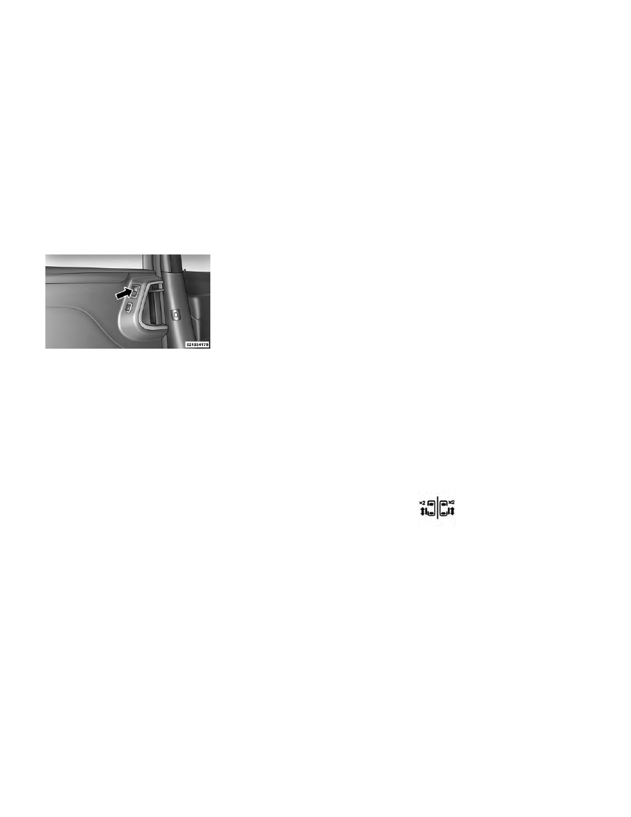
There are power sliding side door
switches located on the b-pillar trim
panel, just in front of the power slid-
ing door for the rear seat passengers
and in the overhead console for the
driver and passengers. Pressing the
switch once will open the power slid-
ing door. If the switch is pressed while
the door is under a power cycle, the
door will reverse direction.

NOTE: The power sliding side
door must be unlocked before the
power sliding door switches will
operate.

To avoid unintentional operation of
the power sliding doors from the rear
seats, press the power sliding door
master lock button, located in the
overhead console, to disable the
switches and handles for the rear seat
passengers.

NOTE:

• The power sliding side door

switches will not open the power
sliding door if the shift lever is in
gear or the vehicle speed is
above 0 km/h. To close the
power sliding door with the shift

lever in gear and vehicle speed
at 0 km/h, the brake must be
pressed.

• If anything obstructs the power

sliding side door while it is clos-
ing or opening, the door will au-
tomatically reverse to the closed
or open position, provided it
meets sufficient resistance.

• If the power sliding side door is

not in the full open or close po-
sition, it will fully open when a
power sliding door switch is
pressed. To close the door, wait
until it is fully open and then
press the switch again.

• If the power sliding door en-

counters multiple obstructions
within the same cycle, the sys-
tem will automatically stop, the
power sliding door motor will
make a clicking sound until the
door has no further movement.
This clicking sound can be
stopped by pulling the inside or
outside handle. If this condition
occurs, no damage is done to the
power sliding door motor. The

Power Sliding Door Switch

30

-------------------------------------------------------------------------------------------------------------------------------------------------------------

power sliding door must be
opened or closed manually.

WARNING!

You, or others, could be injured if
caught in the path of the sliding
door. Make sure the door path is
clear before closing the door.

Power Sliding Side Door Open
Flash

The left and right exterior hazard
lights will flash for 12 seconds when
either sliding door is opened. This will
alert other drivers in the area that
passenger(s) could be entering or ex-
iting the vehicle.

The Sliding Side Door Open Flash can
be enabled or disabled by performing
the following procedure:

1. Place the Key Fob in the ignition
switch.

2. Cycle the ignition switch from ON/
RUN to OFF five times ending in the
ON/RUN position (do not start the
engine).

3. Within 10 seconds of the final
cycle, press the HAZARD switch ON.

4. A single chime will sound to sig-
nify that you have successfully com-
pleted the programming.

You can turn the feature back on by
repeating the previous procedure.

Power Sliding Side Door Master
Lock Switch

To provide a safer environment for
small children riding in the rear seats,
the second row sliding door switches
and handles may be overridden by
pressing the OFF side of the Master
Lock Out Switch located in the front
overhead console.

When the power sliding door master
lock switch is in the OFF position, the
power sliding side door may not be
opened or closed by pressing the
switch located on the b-pillar trim
panel, just in front of the sliding door
or activating the inside power sliding
door handle.

SLIDING SIDE DOOR
CHILD PROTECTION
LOCK

To provide a safer environment for
small children riding in the rear seats,
the sliding doors are equipped with a
Child Protection Door Lock system.

NOTE: When the Child Protec-
tion Door Lock system is engaged,
the door can be opened only by
using the outside door handle even
though the inside door lock is in
the unlocked position.

Overhead Console Power Sliding

Door Master Switch

1 — Left Sliding
Door

3 — Right Slid-
ing Door

2 — Liftgate

4 — Master Lock

31

-------------------------------------------------------------------------------------------------------------------------------------------------------------

NOTE:

• After engaging the Child Protec-

tion Door Lock, always test the
door from the inside to make
certain it is in the desired posi-
tion.

• When the Child Protection Door

Lock system is engaged, (even if
the inside door lock is in the
unlocked position) the door can
be opened only by using the out-
side door handle, the RKE
transmitter, the switches on the
overhead console or the switches
located on the trim panel just in
front of the power sliding door.

• The power sliding side door will

operate from the switches lo-
cated on the trim panel just in
front of the power sliding door,
regardless of the Child Protec-
tion Door Lock lever position. To
avoid unintentional operation of
the power sliding door from the
rear seats, press the "OFF” Mas-
ter Lock Out Switch located in
the front overhead console, next
to the driver.

WARNING!

Avoid trapping anyone in the ve-
hicle in a collision. Remember that
the sliding doors can only be
opened from the outside door
handle or the switches located on
the b-pillar trim panel just in front
of the power sliding door when the
Child Protection Door Locks are
engaged.

To Engage the Child Protection
Door Lock

1. Open the sliding side door.

2. Slide the Child Protection Door
Lock control inward (toward the ve-
hicle) to engage the Child Protection
Door Lock.

3. Repeat Steps 1 and 2 on the oppo-
site sliding door.

NOTE:

• After engaging the Child Protec-

tion Door Lock, always test the
door from the inside to make
certain it is in the desired posi-
tion.

• When the Child Protection Door

Lock system is engaged, (even if
the inside door lock is in the
unlocked position) the door can
be opened only by using the out-
side door handle, the RKE
transmitter, the switches on the
overhead console or the switches
located on the trim panel just in
front of the power sliding door.

• The power sliding side door will

operate from the switches lo-
cated on the b-pillar trim panel,
just in front of the power sliding
door, regardless of the Child
Protection Door Lock lever po-
sition. To avoid unintentional
operation of the power sliding
door from the rear seats, press

Child Protection Door Lock

32

-------------------------------------------------------------------------------------------------------------------------------------------------------------

the “OFF” Master Lock Out
Switch located in the front over-
head console, next to the driver.

WARNING!

Avoid trapping anyone in the ve-
hicle in a collision. Remember that
the sliding doors can only be
opened from the outside door
handle or the switches located on
the b-pillar trim panel just in front
of the power sliding door when the
Child Protection Door Locks are
engaged.

To Disengage the Child Protection
Door Lock

1. Open the sliding side door.

2. Slide the Child Protection Door
Lock control outward (away from the
vehicle) to disengage the Child Pro-
tection Door Lock.

3. Repeat Steps 1 and 2 on the oppo-
site

sliding

door

(for

versions/

markets, where provided).

NOTE:

• After setting the Child Protec-

tion Door Lock system, always
test the door from the inside to
make certain it is in the desired
position.

• The power sliding side door

switches will not open the power
sliding doors if the vehicle is in
gear or the vehicle speed is
above 0 km/h.

• The power sliding door will op-

erate from the outside door
handle, the RKE transmitter, the
switches on the overhead con-
sole, or the switches located on
the b-pillar trim panel just in
front of the power sliding door
when the shift lever is in PARK,
regardless of the child lock lever
position.

LIFTGATE

On vehicles equipped with power
locks, the liftgate can be unlocked
using the Remote Keyless Entry

(RKE) transmitter button, or by acti-
vating the power door lock switches
located on the front doors.

To open the liftgate, press the liftgate
release handle located on the under-
side of the license plate bar and pull
the liftgate open with one fluid mo-
tion.

POWER LIFTGATE (for
versions/markets, where
available)

The power liftgate may be opened
manually or by using the button on
the Remote Keyless Entry (RKE)
transmitter. Press the button on the
transmitter twice within five seconds,
to open the power liftgate. When the

Liftgate Handle Location

33

-------------------------------------------------------------------------------------------------------------------------------------------------------------

liftgate is fully open, pressing the but-
ton twice within five seconds, a sec-
ond time, will close the liftgate.

The power liftgate may also be
opened and closed by pressing the
button located on the overhead con-
sole.

The power liftgate may be closed by
pressing the button, located in the
upper left trim in the liftgate opening.
Pushing once will only close the lift-
gate. This button cannot be used to
open the liftgate.

When the RKE transmitter button is
pressed and the Flash Lights feature
is enabled, the tail lights will flash and
several audible beeps will occur to
signal that the liftgate is opening or
closing.

WARNING!

During power operation, personal
injury or cargo damage may occur.
Ensure the liftgate travel path is
clear. Make sure the liftgate is
closed and latched before driving
away.

NOTE:

• If anything obstructs the power

liftgate while it is closing or
opening, the liftgate will auto-
matically reverse to the closed or
open position, provided it meets
sufficient resistance.

• There are also pinch sensors at-

tached to the side of the liftgate
opening. Light pressure any-
where along these strips will
cause the liftgate to return to the
open position.

• During

power

operation,

whether liftgate is fully open or
fully closed, the liftgate chime
will beep several times indicat-
ing

power

operation

is

in

progress.

• The power liftgate must be in the

full open or close positions for
any of the buttons to operate. If
the liftgate is not in the full open
or close positions, it must be
opened or closed manually.

Overhead Console Master Power

Switch

1 — Left Door

3 — Right Door

2 — Liftgate

4 — Master Lock

Rear Power Liftgate Switch

34

-------------------------------------------------------------------------------------------------------------------------------------------------------------

• If the liftgate release button is

activated while the power lift-
gate is closing, the liftgate will
reverse to the full open position.

• The power liftgate buttons will

not operate if the shift lever is in
gear or the vehicle speed is
above 0 km/h.

• The power liftgate will not oper-

ate in temperatures below −24°C
or temperatures above 62°C. Be
sure to remove any buildup of
snow or ice from the liftgate be-
fore pressing any of the power
liftgate buttons.

• If the power liftgate encounters

multiple obstructions within the
same cycle, the system will auto-
matically stop and must be
opened or closed manually.

WARNING!

• Driving with the liftgate open can

allow poisonous exhaust gases
into your vehicle. You and your
passengers could be injured by
these fumes. Keep the liftgate
closed when you are operating the
vehicle.

• If you are required to drive with

the liftgate open, make sure that
all windows are closed, and the
climate control blower switch is
set at high speed. Do not use the
recirculation mode.

OCCUPANT RESTRAINTS

Some of the most important safety
features in your vehicle are the re-
straint systems:

• Three-point lap and shoulder belts

for all seating positions

• Advanced Front Air Bags for driver

and front passenger

• Supplemental Active Head Re-

straints (AHR) located on top of the
front seats (integrated into the head
restraint)

• Supplemental Side Air Bag Inflat-

able Curtains (SABIC) that span
the front, second, and third row
seating for the driver and passen-
gers seated next to a window

• Supplemental Seat-Mounted Side

Air Bags (SAB)

• An energy-absorbing steering col-

umn and steering wheel

• Knee bolsters/blockers for front

seat occupants

• Front seat belts incorporate preten-

sioners that may enhance occupant
protection by managing occupant
energy during an impact event

• All seat belt systems (except the

driver’s) include Automatic Locking
Retractors (ALRs), which lock the
seat belt webbing into position by
extending the belt all the way out
and then adjusting the belt to the

35

-------------------------------------------------------------------------------------------------------------------------------------------------------------

desired length to restrain a child seat
or secure a large item in a seat

If you will be carrying children too
small for adult-sized seat belts, the
seat belts or the ISOFIX feature also
can be used to hold infant and child
restraint systems. For more informa-
tion on ISOFIX, see ISOFIX — Child
Seat Anchorage System.

WARNING!

• Never place a rear facing infant

seat in front of an air bag. A de-
ploying

Passenger

Advanced

Front Air Bag can cause death or
serious injury to a child 12 years
or younger, including a child in a
rearward facing infant seat.

• Only use a rearward-facing child

restraint in a vehicle with a rear
seat.

NOTE: The Advanced Front Air
Bags have a multistage inflator de-
sign. This allows the air bag to
have different rates of inflation
based on several factors, including
the severity and type of collision.

Please pay close attention to the infor-
mation in this section. It tells you how
to use your restraint system properly,
to keep you and your passengers as
safe as possible.

Buckle up even though you are an
excellent driver, even on short trips.
Someone on the road may be a poor
driver and cause a collision that in-
cludes you. This can happen far away
from home or on your own street.

Research has shown that seat belts
save lives, and they can reduce the
seriousness of injuries in a collision.
Some of the worst injuries happen
when people are thrown from the ve-
hicle. Seat belts reduce the possibility
of ejection and the risk of injury
caused by striking the inside of the
vehicle. Everyone in a motor vehicle
should be belted at all times.

LAP/SHOULDER BELTS

All seating positions in your vehicle
are equipped with combination lap/
shoulder belts.

The belt webbing in the retractor is
designed to lock during very sudden

stops or collisions. This feature allows
the shoulder part of the belt to move
freely with you under normal condi-
tions. However, in a collision the belt
will lock and reduce the risk of you
striking the inside of the vehicle or
being thrown out.

The driver is responsible for respect-
ing, and ensuring that all the other
occupants of the car also respect, the
local laws in force in relation to the
use of the seat belts. Always fasten the
seat belts before starting.

WARNING!

• It is dangerous to ride in a cargo

area, inside or outside of a ve-
hicle. In a collision, people riding
in these areas are more likely to
be seriously injured or killed.

• Do not allow people to ride in any

area of your vehicle that is not
equipped with seats and seat
belts.

• Be sure everyone in your vehicle is

in a seat and using a seat belt
properly.

(Continued)

36

-------------------------------------------------------------------------------------------------------------------------------------------------------------

WARNING!

(Continued)

• Wearing a seat belt incorrectly is

dangerous. Seat belts are de-
signed to go around the large
bones of your body. These are the
strongest parts of your body and
can take the forces of a collision
the best.

• Wearing your belt in the wrong

place could make your injuries in
a collision much worse. You
might suffer internal injuries, or
you could even slide out of part of
the belt. Follow these instructions
to wear your seat belt safely and
to keep your passengers safe, too.

• Two people should never be

belted into a single seat belt.
People belted together can crash
into one another in a collision,
hurting one another badly. Never
use a lap/shoulder belt or lap belt
for more than one person, no
matter what their size.

Lap/Shoulder Belt Operating
Instructions

1. Enter the vehicle and close the
door. Sit back and adjust the seat.

2. The seat belt latch plate is near the
seatback of the front seats and next to
your arm in the rear seats. Grasp the
latch plate and pull out the belt. Slide
the latch plate up the webbing as far
as necessary to allow the belt to go
around your lap.

WARNING!

• A belt that is worn under your

arm is dangerous. Your body
could strike the inside surfaces of

(Continued)

WARNING!

(Continued)

the vehicle in a collision, increas-
ing head and neck injury. A belt
worn under the arm can cause
internal injuries. Ribs aren't as
strong as shoulder bones. Wear
the belt over your shoulder so that
your strongest bones will take the
force in a collision.

• A shoulder belt placed behind you

will not protect you from injury
during a collision. You are more
likely to hit your head in a collision
if you do not wear your shoulder
belt. The lap and shoulder belt are
meant to be used together.

3. When the belt is long enough to fit,
insert the latch plate into the buckle
until you hear a “click”.

Pulling Out Belt And Latch Plate

Inserting Latch Plate Into Buckle

37

-------------------------------------------------------------------------------------------------------------------------------------------------------------

WARNING!

• A belt that is buckled into the

wrong buckle will not protect you
properly. The lap portion could
ride too high on your body, possi-
bly causing internal injuries. Al-
ways buckle your belt into the
buckle nearest you.

• A belt that is too loose will not

protect you properly. In a sudden
stop you could move too far for-
ward, increasing the possibility of
injury. Wear your seat belt snugly.

4. Position the lap belt across your
thighs, below your abdomen. To re-
move slack in the lap belt portion, pull
up on the shoulder belt. To loosen the
lap belt if it is too tight, tilt the latch
plate and pull on the lap belt. A snug
belt reduces the risk of sliding under
the belt in a collision.

WARNING!

• A lap belt worn too high can in-

crease the risk of injury in a colli-
sion. The belt forces won't be at
the strong hip and pelvic bones,
but across your abdomen. Always
wear the lap part of your seat belt
as low as possible and keep it
snug.

• A twisted belt may not protect

you properly. In a collision, it
could even cut into you. Be sure
the belt is straight. If you can't
straighten a belt in your vehicle,
take it to your authorized dealer
immediately and have it fixed.

(Continued)

WARNING!

(Continued)

• Do not use devices (clips, fasten-

ings etc.) that prevent the seat
belts from laying close to the oc-
cupants' bodies.

• Do not carry children on a pas-

senger’s lap using only one seat
belt for protecting both of them.

5. Position the shoulder belt on your
chest so that it is comfortable and not
resting on your neck. The retractor
will withdraw any slack in the belt.

6. To release the belt, push the red
button on the buckle. The belt will
automatically retract to its stowed po-
sition. If necessary, slide the latch
plate down the webbing to allow the
belt to retract fully.

Removing Slack From Belt

38

-------------------------------------------------------------------------------------------------------------------------------------------------------------

WARNING!

A frayed or torn belt could rip apart
in a collision and leave you with no
protection. Inspect the belt system
periodically, checking for cuts,
frays, or loose parts. Damaged
parts must be replaced immedi-
ately. Do not disassemble or modify
the system. Seat belt assemblies
must be replaced after a collision if
they have been damaged (bent re-
tractor, torn webbing, etc.).

Third Row Center Shoulder Belt
Instructions

The shoulder belt for the third row
center seat is located in the headliner
slightly behind the third row seat.

Pull the strap down and secure the
small latch plate of the lap belt into
the small buckle until you hear a
“click”.

Position the shoulder belt on your
chest so that it is comfortable and not
resting on your neck. When the belt is
long enough to fit , insert the large
latch plate into the buckle until you

hear a “click.” The retractor should
withdraw any slack in the belt.

To release the small latch plate, posi-
tion the end of the large latch plate
against the red button on the small
latch plate and push upward. Rein-
stall the latch plates into the head-
liner.

Lap/Shoulder Belt Untwisting
Procedure

Use the following procedure to un-
twist a twisted lap/shoulder belt.

1. Position the latch plate as close as
possible to the anchor point.

2. At about 15 to 30 cm above the
latch plate, grasp and twist the belt
webbing 180 degrees to create a fold
that begins immediately above the
latch plate.

3. Slide the latch plate upward over
the folded webbing. The folded web-
bing must enter the slot at the top of
the latch plate.

4. Continue to slide the latch plate up
until it clears the folded webbing.

Adjustable Upper Shoulder Belt
Anchorage

In the front seats and the second row
outboard seats, the shoulder belt an-
chorage can be adjusted upward or
downward to help position the belt
away from your neck. The upper an-
chorage can be adjusted upward by
pushing anywhere on the anchorage.
To move the anchorage downward,
squeeze the actuation buttons while
simultaneously pushing down on the
anchorage assembly.

As a guide, if you are shorter than
average you will prefer a lower posi-
tion, and if you are taller than average
you will prefer a higher position.
When you release the anchorage, try
to move it up or down to make sure
that it is locked in position.

WARNING!

The seat belts height must only be
adjusted when the vehicle is sta-
tionary.

39

-------------------------------------------------------------------------------------------------------------------------------------------------------------

SEAT BELTS IN
PASSENGER SEATING
POSITIONS

The seat belts in the passenger seating
positions are equipped with Auto-
matic Locking Retractors (ALR)

which are used to secure a child re-
straint system. For additional infor-
mation, refer to “Installing Child Re-
straints Using The Vehicle Seat Belt”

under the “Child Restraints” section.
The chart below defines the type of
feature for each seating position.

Driver

Center

Passenger

First Row

N/A

N/A

ALR (for versions/markets, where

provided)

Second Row

ALR

N/A

ALR

Third Row

ALR

CINCH

ALR

• N/A — Not Applicable

• ALR — Automatic Locking Retractor

If the passenger seating position is
equipped with an ALR and is being
used for normal usage:

Only pull the belt webbing out far
enough to comfortably wrap around
the occupant's mid-section so as to not
activate the ALR. If the ALR is acti-
vated, you will hear a ratcheting sound
as the belt retracts. Allow the webbing
to retract completely in this case and
then carefully pull out only the amount
of webbing necessary to comfortably

wrap around the occupant's mid-
section. Slide the latch plate into the
buckle until you hear a "click."

AUTOMATIC LOCKING
RETRACTOR MODE (ALR)

In this mode, the shoulder belt is auto-
matically pre-locked. The belt will still
retract to remove any slack in the
shoulder belt. The Automatic Locking
Mode is available on all passenger-
seating positions with a combination
lap/shoulder belt. Use the Automatic
Locking Mode anytime a child safety
seat is installed in a seating position

that has a belt with this feature. Chil-
dren 12 years old and under should
always be properly restrained in the
rear seat.

How To Engage The Automatic
Locking Mode

1. Buckle the combination lap and
shoulder belt.

2. Grasp the shoulder portion and
pull downward until the entire belt is
extracted.

40

-------------------------------------------------------------------------------------------------------------------------------------------------------------

3. Allow the belt to retract. As the
belt retracts, you will hear a clicking
sound. This indicates the safety belt is
now in the Automatic Locking Mode.

How To Disengage The Automatic
Locking Mode

Unbuckle

the

combination

lap/

shoulder belt and allow it to retract
completely to disengage the Auto-
matic Locking Mode and activate the
vehicle sensitive (emergency) locking
mode.

WARNING!

• The belt and retractor assembly

must be replaced if the seat belt
assembly Automatic Locking Re-
tractor (ALR) feature or any
other seat belt function is not
working properly when checked
according to the procedures in the
Service Manual.

• Failure to replace the belt and

retractor assembly could increase
the risk of injury in collisions.

ENERGY MANAGEMENT
FEATURE

This vehicle has a safety belt system
with an energy management feature
in the front seating positions to help
further reduce the risk of injury in the
event of a head-on collision. This
safety belt system has a retractor as-
sembly that is designed to release
webbing in a controlled manner. This
feature is designed to help reduce the
belt force acting on the occupant’s
chest.

WARNING!

• The belt and retractor assembly

must be replaced if the seat belt
assembly Automatic Locking Re-
tractor (ALR) feature or any
other seat belt function is not
working properly when checked
according to the procedures in the
Service Manual.

• Failure to replace the belt and

retractor assembly could increase
the risk of injury in collisions.

SEAT BELT
PRETENSIONERS

The seat belts for both front seating
positions are equipped with preten-
sioning devices that are designed to
remove slack from the seat belt in the
event of a collision. These devices may
improve the performance of the seat
belt by assuring that the belt is tight
about the occupant early in a colli-
sion. Pretensioners work for all size
occupants, including those in child
restraints.

NOTE: These devices are not a
substitute for proper seat belt
placement by the occupant. The
seat belt still must be worn snugly
and positioned properly.

The pretensioners are triggered by the
Occupant

Restraint

Controller

(ORC). Like the air bags, the preten-
sioners are single use items. A de-
ployed pretensioner or a deployed air
bag must be replaced immediately.

41

-------------------------------------------------------------------------------------------------------------------------------------------------------------

SUPPLEMENTAL ACTIVE
HEAD RESTRAINTS (AHR)
— (for versions/markets
where provided)

These head restraints are passive, de-
ployable components, and vehicles
with this equipment cannot be readily
identified by any markings, only
through visual inspection of the head
restraint. The head restraint will be
split in two halves, with the front half
being soft foam and trim, the back
half being decorative plastic.

How The Active Head Restraints
(AHR) Work

The Occupant Restraint Controller
(ORC) determines whether the sever-
ity, or type of rear impact will require
the Active Head Restraints (AHR) to
deploy. If a rear impact requires de-
ployment, both the driver and front
passenger seat AHRs will be deployed.

When AHRs deploy during a rear im-
pact, the front half of the head re-
straint extends forward to minimize
the gap between the back of the occu-
pant’s head and the AHR. This system

is designed to help prevent or reduce
the extent of injuries to the driver and
front passenger in certain types of
rear impacts.

NOTE: The

Active

Head

Re-

straints (AHR) may or may not de-
ploy in the event of a front or side
impact. However if during a front
impact, a secondary rear impact
occurs, the AHR may deploy based
on several factors, including the
severity and type of the impact.

CAUTION!

All occupants, including the driver,
should not operate a vehicle or sit in
a vehicle's seat until the head re-
straints are placed in their proper
positions in order to minimize the
risk of neck injury in the event of a
collision.

NOTE: For more information on
properly adjusting and positioning
the head restraint, refer to “Ad-
justing Active Head Restraints” in
“Understanding The Features Of
Your Vehicle”.

Resetting Active Head Restraints
(AHR)

If the Active Head Restraints are trig-
gered in a collision, you must reset the
head restraint on the driver’s and
front passenger seat. You can recog-
nize when the Active Head Restraint
has been triggered by the fact that
they have moved forward (as shown
in step three of the resetting proce-
dure).

1. Grasp the deployed AHR from the
rear seat.

Active Head Restraint (AHR)

Components

1 — Head Re-
straint Front Half
(Soft Foam and
Trim)

3 — Head Re-
straint Back Half
(Decorative Plas-
tic Rear Cover)

2 — Seatback

4 — Head Re-
straint Guide Tubes

42

-------------------------------------------------------------------------------------------------------------------------------------------------------------

2. Position the hands on the top of
the deployed AHR at a comfortable
position.

3. Pull down then rearward to-
wards the rear of the vehicle then
down to engage the locking mecha-
nism.

4. The AHR front soft foam and trim
half should lock into the back decora-
tive plastic half.

NOTE:

• If you have difficulties or prob-

lems resetting the Active Head
Restraints, see an authorized
dealer.

• For safety reasons, have the Ac-

tive Head Restraints checked by
a qualified specialist at an au-
thorized dealer.

ACTIVE HOOD SYSTEM

The Active Hood system is intended to
enhance pedestrian protection by el-
evating the vehicle’s hood upon an
impact with a pedestrian or other ob-
ject. The system is automatically acti-
vated when the vehicle is moving
within a specified vehicle speed range.
In order to detect a range of pedestri-
ans, other objects that are impacted
may result in an Active Hood deploy-
ment.

Deployment Sensors And Controls

The Electronic Pedestrian Protection
Module (EPPM) determines if deploy-
ment of the actuators in a frontal im-
pact is required. Based on the impact
sensors signals, the EPPM determines
when to deploy the actuators. The
impact sensors are located within the
front bumper area.

The EPPM monitors the readiness of
the electronic parts of the Active Hood

Hand Positioning Points On AHR

1 — Downward Movement

2 — Rearward Movement

3 — Final Downward Movement To
Engage Locking Mechanism

AHR In Reset Position

43

-------------------------------------------------------------------------------------------------------------------------------------------------------------

system whenever the ignition switch is
in the START or ON/RUN position. If
the key is in the LOCK position, in the
ACC position, or not in the ignition,
the Active Hood system is not on and
the Active Hood will not deploy.

The EPPM contains a backup power
supply system that may deploy the
actuators even if the battery loses
power or it becomes disconnected
prior to deployment.

Service Active Hood System

If the EPPM has deployed the Active
Hood, or if it detects a malfunction in
any part of the system, it turns on the
Air Bag Warning Light and it will
display

the

“SERVICE

ACTIVE

HOOD” message in the Electronic Ve-
hicle Information Center (EVIC), for
versions/markets, where provided. A
single chime will sound if the Air Bag
Warning Light comes on again after
initial startup. It also includes diag-
nostics that will illuminate the Air Bag
Warning Light if a malfunction is
noted that could affect the Active
Hood system. The diagnostics also re-
cord the nature of the malfunction. If

the Air Bag Warning Light is illumi-
nated, or if “SERVICE ACTIVE
HOOD” appears in the EVIC, see
your authorized dealer.

In the event of an Active Hood deploy-
ment, the vehicle should be serviced
by an authorized dealer. The hood
hinges must be serviced and the ac-
tuator assemblies replaced to restore
system functionality.

Following an Active Hood deploy-
ment, the hood position can be tem-
porarily reset by pushing down at the
rear edge over the hood hinges as the
internal pressure of each actuator is
relieved. The temporary hood reset
position is intended to improve for-
ward driving visibility over the hood
until the vehicle can be serviced. The
temporary hood reset position will
leave the hood approximately 5 mm
above the fender surface.

The front bumper assembly may af-
fect proper operation of the Active
Hood system. The front bumper com-
ponents should be inspected for dam-
age and replaced if necessary in the
event of a frontal impact, even if it
occurs at a low rate of speed.

NOTE: After any Active Hood de-
ployment, the vehicle should be
taken to an authorized dealer im-
mediately.

Temporary Hood Reset Position

44

-------------------------------------------------------------------------------------------------------------------------------------------------------------


Content      ..      1      2      3      ..