Lancia NUOVA YPSILON. Service Manual - part 2


  Index      Manuals     Lancia NUOVA YPSILON. Service Manual


Search            copyright infringement  


Content      ..      1      2      3      ..


Lancia NUOVA YPSILON. Service Manual - part 2


IMPORTANT It is advisable to switch the air recirculation on whilst queueing or in tunnels to prevent the introduction of polluted
air. However, it is better not to use the function for long periods, particularly if there are many people on board, to prevent the
windows from misting.
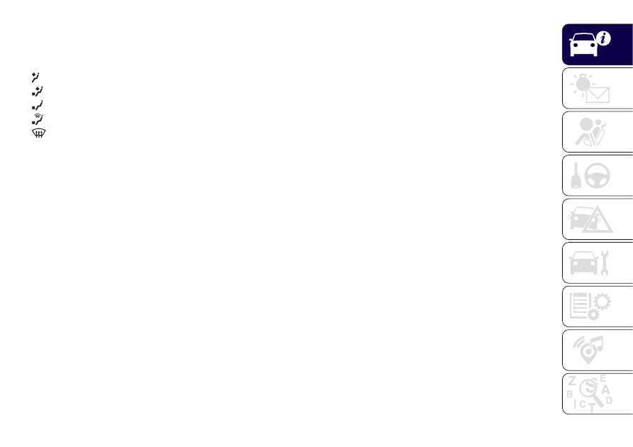
C - Air distribution knob:

towards the body and the side windows

towards the body, the side windows and the feet

towards the feet only

towards the feet and the windscreen

towards the windscreen only

D - Heated rear window activation/deactivation button. The LED on the button switches on to indicate activation.
E - Fan speed adjustment knob.

Note To stop the air flow from the vents turn the knob to 0.
F - Climate control system compressor on/off button. Press the button to activate the climate control system; the LED on the
button switches on (this enables rapid cooling of the passenger compartment).

ADDITIONAL HEATER

(for versions/markets, where provided)

This device speeds up passenger compartment warming when it is very cold. The additional heater turns off automatically after
the required comfort conditions are achieved.
The heater activates automatically when knob A is turned to the last red section and the fan is activated (knob E turned to at
least 1

st

speed).

The heater only operates if the outside temperature and engine coolant temperature are low. The heater will not activate if the
battery voltage is too low.

23

-------------------------------------------------------------------------------------------------------------------------------------------------------------

AUTOMATIC CLIMATE CONTROL SYSTEM

(for versions/markets, where provided)

Controls

A - Manual air distribution selection
By pressing the buttons, one of the five possible air flow distribution patterns can be selected:

air flow to the windscreen and front side window diffusers to demist or defrost them.

air flow to central and side dashboard vents to ventilate the chest and the face during the hot season.

air flow to the front seat feet area diffusers. Due to the natural tendency of heat to spread upwards, this type of
distribution warms the passenger compartment up as quickly as possible, providing an immediate feeling of warmth.

+

distribution between feet area diffusers (warmest air) and dashboard diffusers (coolest air).

23

L0F0129C

24

GETTING

TO

KNOW

YOUR

CAR

-------------------------------------------------------------------------------------------------------------------------------------------------------------

+

distribution between footwell diffusers and windscreen/front side window vents. This type of distribution achieves
effective heating of the passenger compartment and prevents the windows from misting up.

B - Activation/deactivation of the MAX-DEF function (fast front window defrosting/demisting).
C - Climate control system compressor activation/deactivation.
D - Internal air recirculation activation/deactivation button.
E - AUTO function activation (climate control system automatic operation).
F - heated rear window on/off.
G - Fan speed adjustment knob.
H - Climate control on/off.
I/L - Adjustment of temperature inside the passenger compartment.
NOTE In particularly severe climate conditions it is recommended to limit the use of the Stop/Start function to prevent the
compressor from continuously switching on and off, with consequent rapid misting of the windows and accumulation of
humidity with unpleasant smells in the passenger compartment.

WARNING

19) It is advisable not to use the internal air recirculation function when the outside temperature is low, because the windows could mist
rapidly.

WARNING

2) The system uses R134a coolant which does not pollute the environment in the event of accidental leakage. Never use R12 fluid, which is
not compatible with the system components.

25

-------------------------------------------------------------------------------------------------------------------------------------------------------------

ELECTRIC WINDOWS

20)

These operate when the ignition key is
turned to MAR-ON and for about
three minutes after the ignition key is
turned to STOP or removed unless one
of the front doors is opened.

Driver side front door controls

All windows can be controlled from the
driver side door panel fig. 24.

A: front left window opening/closing;
“continuous automatic” operation
during window opening/closing stage;
B: opening/closing front right window;
"continuous automatic" operation
during window opening/closing stage
(for versions/markets, where provided)
C: enabling/disabling of rear door
electric window controls;

D: rear left window opening/closing (for
versions/markets where provided);
“continuous automatic” operation
during window opening/closing stage;
E: opening/closing rear right window
(for versions/markets, where provided);
"continuous automatic" operation
during window opening/closing stage.
Use the buttons to open/close the
desired window.
When one of the two buttons is
pressed briefly, the window moves in
stages; if the button is held down,
"continuous automatic" operation is
activated both for closing and opening
(only with ignition key at MAR).

Anti-crush safety device

(for versions/markets, where provided)

11)

This safety system detects the
presence of an obstacle during the
window closing travel and intervenes by
stopping and reversing the window
travel, depending on its position.
The anti-pinch function is active both
during manual and automatic operation
of the electric windows. Following the
intervention of the anti-pinch system,
the window travel is immediately
interrupted and subsequently reversed
until the lower end of travel is reached.
The window cannot be operated in
any way during this time.

Electric window system
initialisation

If power supply is interrupted when the
window is moving, the electric window
automatic operation must be
reinitialised.
The initialisation procedure must be
carried out with the doors closed and
for each door, as described below:
❒ fully close the window to be
initialised, with manual operation;
❒ after the window has reached the
upper end of travel, hold the up button
pressed for at least one second.

WARNING

20) Improper use of the electric windows
can be dangerous. Before and during
operation, always check that nobody is
exposed to the risk of being injured either
directly by the moving window or through
objects getting caught or hit by it. When
leaving the vehicle, always remove the
ignition key to avoid the risk of injury for
people still on board due to accidental
operation of the electric windows.

24

L0F0162C

26

GETTING

TO

KNOW

YOUR

CAR

-------------------------------------------------------------------------------------------------------------------------------------------------------------

WARNING

11) The system conforms to the
2000/4/EC standard concerning the safety
of passengers leaning out of the passenger
compartment.

ELECTRIC SUN
ROOF

(for versions/markets, where provided)

21)

12)

The large electric sun roof comprises
two glass panels; the front one is
mobile and the rear one fixed. These
are equipped with two sun blinds (front
and rear) that can be moved manually.
With the sun roof closed, the blinds can
be placed in any position.
To open the blinds, grip handle A fig.
25, following the direction indicated by
the arrow until the desired position is
reached. To close them, carry out
the procedure in reverse.
The sun roof can be operated only with
the ignition key turned to MAR.
Controls B and C fig. 25 on the front
roof light trim control the sun roof
opening/closing.
Opening
Press and hold down button C. The
front glass panel will move to the spoiler
position.
Press the button again, holding it down
for more than half a second to
automatically move the sun roof to an
intermediate position (“Comfort”
position).

After opening in spoiler position, press
button B once again for more than
half a second to bring the roof
automatically to fully open position.
Closing
Press button B from the fully open
position. Press the button for more than
half a second to automatically move
the sunroof to spoiler position.

25

L0F0152C

27

-------------------------------------------------------------------------------------------------------------------------------------------------------------

After opening in spoiler position, press
button B again for more than half a
second to bring the roof automatically
to fully closed position.

ANTI-PINCH SAFETY
DEVICE

The sun roof has an anti-pinch safety
system capable of detecting the
presence of an obstacle whilst the roof
is closing: if this happens, the system
intervenes and the movement of the
glass is immediately reversed.

EMERGENCY OPERATION

If the control buttons fail to operate, the
sun roof can be moved manually
proceeding as described below:
❒ remove the protective cap located on
the internal lining, between the two
sun blinds;
❒ take the Allen key provided and
located in the tool box in the luggage
compartment or, depending on the
version, inside the glove compartment;
❒ introduce the key provided into
housing A fig. 26 and turn it clockwise
to open the roof or anticlockwise to
close the roof.

INITIALISATION
PROCEDURE

Following an automatic movement
malfunction while opening/closing or
after an emergency manoeuvre (see
description in the previous paragraph),
the automatic operation of the sun
roof must be initialised again.
Proceed as follows:
❒ Press button B in closed position;
❒ hold down button B: after
approximately 10 seconds the roof
moves jerkily to closing position. Once
the operation has ended (roof closed)
release button B;
❒ turn the ignition key to STOP and
keep it there for 10 seconds;
❒ turn the ignition key to the MAR
position;
❒ Press button B in closed position;

❒ hold down button B until the roof is
completely closed: the initialisation
procedure has ended;
❒ press button B again within 3
seconds from the conclusion of the
initialisation procedure;
❒ hold down button B: the roof will
perform an automatic opening and
closing cycle: should this not occur,
repeat the operation from the
beginning;
❒ keeping button B held down, wait
until the roof is completely closed.

WARNING

21) When leaving the vehicle, always
remove the key from the ignition switch to
avoid the risk of injury to those still inside
the car due to accidental operation of
the sun roof. Improper use of the roof can
be dangerous. Before and during
operation, always check that no-one is
exposed to the risk of being injured by the
moving sunroof or by objects getting
caught or hit by it.

WARNING

12) Do not open the sun roof if there is
snow or ice on it: you may damage it. In
vehicles with sun roof no roof rack can be
fitted.

26

L0F0299C

28

GETTING

TO

KNOW

YOUR

CAR

-------------------------------------------------------------------------------------------------------------------------------------------------------------

CONTROLS

DUALDRIVE ELECTRIC
POWER STEERING

(for versions/markets, where provided)

This only operates with the ignition
key turned to MAR and the engine
started. Electric power steering allows
the force required at the steering wheel
to be adapted to the driving conditions.

IMPORTANT When turning the ignition
key quickly, full power steering
functionality can be achieved after a
few seconds.

Activation / Deactivation (CITY
function)

Press the CITY button (A-fig. 27) to
activate the function. When this
function is active, the word CITY on the
instrument panel will light up.

When the CITY function is on, the
steering wheel effort is lighter, making
parking easier: therefore, this function is
particularly useful for driving in city
centres.
To deactivate the function press the
button again.

IMPORTANT During parking
manoeuvres requiring a lot of steering,
the steering may become harder: this is
normal and is due to the intervention
of the system to protect the electric
steering motor from overheating, so no
repair is required. When the car is
used again later on, the power steering
will work normally.

ECO FUNCTION

(for versions/markets, where provided)

Press the ECO button fig. 28 for at least
5 seconds to activate the function.

When the ECO function is activated,
the car is set for city driving,
characterised by less effort on the
steering wheel (Dualdrive system on)
and reduced fuel consumption.
When this function is activated, the
word ECO on the display will light up on
some versions.
This function stays in the memory, so
when the vehicle is started again,
the system keeps the setting it had
before the engine was stopped. Press
the ECO button again to deactivate
the function and restore the normal
driving setting.

WARNING

22) It is absolutely forbidden to carry out
any after-market operation involving
steering system or steering column
modifications (e.g. installation of anti-theft
device) that could adversely affect
performance and safety, invalidate the
warranty and also result in the car not
meeting type-approval requirements.
23) Before starting any servicing operation,
stop the engine and remove the key from
the ignition switch to operate the steering
lock, particularly when the wheels do
not touch the ground. If this is not possible
(for example if the key needs to be turned
to MAR or the engine must be running),
remove the main fuse that protects the
electric power steering.

27

L0F0428C

28

L0F0039C

29

-------------------------------------------------------------------------------------------------------------------------------------------------------------

BONNET

24) 25)

13)

OPENING

Proceed as follows:
❒ pull lever A fig. 29 in the direction
indicated by the arrow;

❒ move lever B fig. 30 to the left as
shown in the figure;

❒ lift the bonnet and, at the same time,
release the supporting rod C fig. 31
from its catch D, then insert the end of
the rod into housing E in the bonnet
(larger hole) and push to safety position
(smaller hole), as shown in the figure.

CLOSING

Proceed as follows:
❒ keep the bonnet raised with one
hand and remove rod C fig. 31 from
housing D with the other, inverting the
opening motion, then fit it back into
its catch;
❒ lower the bonnet to approximately 20
centimetres from the engine
compartment and let it drop. Make sure
that the bonnet is completely closed
and not only fastened by the locking
device by trying to open it. If it is not
perfectly closed, do not try to press the
bonnet lid down but open it and repeat
the procedure.

IMPORTANT Always check that the
bonnet is closed correctly to prevent it
from opening while the vehicle is
travelling.

WARNING

24) The bonnet may drop suddenly if the
supporting rod is not positioned correctly.
25) Perform these operations only when
the car is stationary.

29

L0F0096C

30

L0F0097C

31

L0F0095C

30

GETTING

TO

KNOW

YOUR

CAR

-------------------------------------------------------------------------------------------------------------------------------------------------------------

WARNING

13) Use both hands to lift the bonnet.
Before lifting, check that the windscreen
wiper arms are not raised from the
windscreen, that the vehicle is stationary
and that the handbrake is engaged.

BOOT

26) 27)

The luggage compartment unlocking is
electrically operated and is deactivated
when the car is in motion.

OPENING

26)

Opening from the outside

When unlocked, the luggage
compartment can be opened from
outside the car using the power handle
A fig. 32 located under the tailgate
edge until the unlocking click is heard
or pressing the

button on the

remote control.

The direction indicators and internal
light will blink twice when the boot
is opened: the light will go out
automatically when the boot is closed.
The light switches off automatically after
a few minutes if the tailgate is left
open.

Emergency opening from inside

Proceed as follows:
❒ remove the rear head restraints and
fully fold the seats;
❒ adjust lever A fig. 33.

32

L0F0031C

33

L0F0041C

31

-------------------------------------------------------------------------------------------------------------------------------------------------------------

LUGGAGE
COMPARTMENT
INITIALISATION

IMPORTANT If the battery is
disconnected or the protection fuse
blows, the luggage compartment
opening/closing mechanism must be
reinitialised as follows: close all the
doors and the tailgate; press the

button on the remote control; press

the

button on the remote control.

WARNING

26) A heavy load that has not been
secured may cause serious injuries to
passengers in the event of an accident.
27) If you are travelling in an area with
limited opportunities for vehicle refuelling
and you wish to bring petrol with you in
a petrol can, you must do so in compliance
with current regulations and using an
approved can, appropriately secured to the
load securing attachments. In the event of
a collision the fire risk is increased all the
same.
28) Be careful not to hit objects on the
storage shelf when you open the tailgate.

VERSION WITH LPG
SYSTEM

INTRODUCTION

29)

14) 15)

The LPG version features two fuel
supply systems: one for petrol and one
for LPG.
Although the LPG system has
numerous safety features, it is advisable
to proceed as follows every time the
car is not in use for a long period or
moved in an emergency as a result of a
breakdown or accident:
❒ unscrew the fixing devices A fig. 35,
then remove the cover B;

❒ close the LPG cock by rotating the
knurled ring nut C fig. 36 clockwise;
❒ refit the cover and retighten the
fastening devices.

34

L0F0193C

35

L0F0238C

32

GETTING

TO

KNOW

YOUR

CAR

CLOSING

Pull the tab A fig. 34 and lower the
tailgate by pressing next to the lock
until it clicks.

IMPORTANT Before closing the
luggage compartment make sure that
you have the keys, since the luggage
compartment is automatically locked.

-------------------------------------------------------------------------------------------------------------------------------------------------------------

IMPORTANT If gas is smelt, switch from
LPG operation to petrol operation and
immediately go to a Lancia Dealerships
to have the vehicle checked and
possible system faults supply excluded.

LPG TANK

16)

The car has a (pressurised) tank A fig.
37 for collecting LPG in a liquid state. It
is ring-shaped and located in the spare
wheel compartment with suitable
protection.

LPG tank certification

The LPG tank is certified in accordance
with the regulations in force.
In Italy, the tank has a life of 10 years
starting from the car registration date. If
the vehicle has been registered in a
country other than Italy, the duration
and the testing/inspection procedures
of the LPG tank can vary depending on
the national provisions in force in that
country. In any case, when the time limit
in the individual country has run out,
contact a Lancia Dealership to have the
tank replaced.

SELECTION OF
PETROL/LPG SUPPLY
TYPE

30)

17) 18) 19) 19) 20) 21)

The petrol/LPG switch A fig. 38 allows
drivers to select petrol or LPG
operation.

To guarantee switching in full safety, the
actual change to the chosen fuel
system takes place depending on the
car usage conditions; it may not
therefore be immediate. Switching is
confirmed by the switching on/off of the

icon on the display.

If the LPG runs out, switching to petrol
takes place automatically. In this case
the display shows the

icon just

above the LPG wording and all the bars
of the edges for the empty notches
light up constantly.

REFUELLING

22)

Maximum refuelling capacity (including
reserve): 30.5 litres. The figure already
takes into account the 80% tank filling
limit and the residual fluid required
for priming; this figure represents the
maximum permitted capacity. In
addition, after different refuelling
processes, this figure may vary due to
differences between the network pump
supply pressures, pumps having
different supply/locking features, tank
not completely run out of fuel.

36

L0F0239C

37

L0F0243C

38

L0F0411C

33

-------------------------------------------------------------------------------------------------------------------------------------------------------------

WARNING

29) Note that in some countries (including
Italy) there are legal restrictions in force
for parking/garaging motor vehicles fuelled
by gas that is denser than air; LPG comes
under this category.
30) Do not switch between the two
operating modes whilst starting the engine.

WARNING

14) The car is equipped with a gaseous
LPG injection system designed specifically
for it: it is therefore absolutely forbidden
to alter the configuration of the system or
its components. The use of other
components or materials could cause
malfunctions and lead to a reduction
in safety. If you experience problems, go to
a Lancia Dealership. When towing or
lifting the vehicle, follow the instructions in
the main handbook under the paragraph
on "Towing the vehicle" to prevent damage
to the gas system parts.

15) When using a painting oven, the LPG
tank should be removed from the car
and later carefully refitted at a Lancia
Dealership. Although the LPG system has
numerous safety features, it is advisable
to proceed as follows every time the
vehicle is not in use for a long period or
moved in an emergency as a result of
a breakdown or accident: unscrew the
fastening devices A fig. 35, then remove
the cover B. Close the LPG cock rotating
the ring nut C fig. 36 clockwise. Refit
the cover and retighten the fastening
devices.
16) Periodically (at least once every six
months) it is advisable to let the LPG in the
tank run out and, at the first refuelling, to
check that it does not exceed the
maximum capacity of 30.5 litres (reserve
included) (with a tolerance of 2 litres
excess). If the level is above 30.5 litres
(reserve included) contact a Lancia
Dealership immediately.
17) The system operates at temperatures
ranging between -20°C and 100°C.
18) If, during LPG operation, LPG runs out,
the system automatically switches to
petrol operation as indicated by the

warning light on the display.

19) Regardless of the last fuel system
used, at the following engine starting, after
the initial petrol stage, the system will
automatically switch to LPG.
20) When switching is requested, metallic
noise from the valves which pressurise
the circuit can be heard. For the switching
logic described above, a delay between the
valve ticking and the switching off of the
instrument panel indication is completely
normal.

21) In particular usage conditions, such as
starting and operation at low ambient
temperature or LPG supply with low
propane content, the system may switch
temporarily to petrol operation, without
a visual indication of switching on the
instrument panel. In the event of low LPG
levels in the tank or request for high
performance (e.g. overtaking, car fully
laden, steep hills) the system may
automatically switch to petrol operation to
guarantee the engine power requested; the
icon

on the display switches on to

indicate this. When the above conditions
are no longer present, the system
automatically restores LPG operation and
the

icon switches off. To achieve the

automatic switching described above,
make sure that there is always enough fuel
in the petrol tank.
22) It is strictly forbidden to use any
additive in the LPG.

34

GETTING

TO

KNOW

YOUR

CAR

-------------------------------------------------------------------------------------------------------------------------------------------------------------

VERSION WITH
METHANE SYSTEM
(Natural Power)

31) 32)

INTRODUCTION

The "Natural Power" version features
two fuel systems, one for petrol and
one for natural gas (methane).

METHANE CYLINDERS

The vehicle is equipped with two
cylinders (total capacity about 72 litres)
fig. 39 fig. 40 located under the floor
of the vehicle and protected by two
special guards.

The methane, stored in the cylinders at
high pressure, flows through a
dedicated pipe to reach the pressure
regulator/reduction unit which supplies
the two methane injectors at low
pressure (about 9 bar).

Cylinder certification

The methane cylinders are certified in
accordance with ECE Regulation no.
110.

The cylinders must be inspected, in
accordance with ECE Regulation
Procedure no. 110, every 4 years from
the car registration date or in
accordance with specific regulations in
individual countries.
The plates provided by the Dealership
with the on board documentation
contain the date for the first inspection
of the cylinders. Methane refuelling
stations are not authorised to refill the
cylinders when the inspection date has
expired.

IMPORTANT If the vehicle has been
registered in a country other than Italy,
the certification data, identification
and inspection procedures for
the methane cylinders should conform
to the legislation in that country. In
any case, remember that the life of the
cylinders is 20 years from the
production date as set out in ECE
Regulation no. 110.

SELECTION OF
PETROL/METHANE
SUPPLY TYPE

33)

23) 24) 25) 26)

This engine normally runs on methane
except during starting when it runs
on petrol.
The (petrol/methane switch) button A
fig. 41 allows drivers to select petrol or
methane operation.

39

L0F0106C

40

L0F0107C

35

-------------------------------------------------------------------------------------------------------------------------------------------------------------

To guarantee switching in full safety, the
actual change to the chosen fuel
system takes place depending on the
car usage conditions; it may not
therefore be immediate.
Switching is confirmed by the switching
on/off of the

icon on the display.

In addition, when starting at outside
temperatures below approximately
–10°C, the switching times from petrol
to methane increase to allow the
pressure regulator/reduction unit to
heat up.
If the methane runs out, switching to
petrol takes place automatically. In this
case the display shows the

icon

just above the CNG wording and all the
bars of the edges for the empty
notches light up constantly.

REFUELLING

Maximum refuelling capacity (including
reserve): 12 kg. The total volume of
cylinders is about 72 litres.

WARNING

31) The car is equipped with a high-
pressure methane system designed to
operate at 200 rated bar. It is dangerous to
stretch the system with higher pressures.
To prevent damage to the methane system
parts when towing or raising the car,
follow the instructions in the "Towing the
vehicle" paragraph in the "In Emergency"
chapter. If there is a problem with the
methane system, only contact a Lancia
Dealership. Do not modify configuration or
components of the methane system;
they have been designed exclusively for
this car. The use of other components
or materials could cause malfunctions and
prejudice safety.
32) When oven painting, the cylinders
should be removed from the vehicle and
later carefully refitted by a Lancia
Dealership. Although the methane system
has numerous safety features, it is
advisable to close the manual cocks for the
cylinders every time the vehicle is not in
use for a long period, transported on other
vehicles or moved in an emergency as a
result of a breakdown or accident.
33) Do not switch between the two
operating modes whilst starting the engine.

WARNING

23) If, during methane operation, the same
runs out, the car switches to petrol
automatically and all the bars on the
display switch off. This displaying remains
until the next methane refuelling.
24) Regardless of the last fuel system
used, at the following engine starting, after
the initial petrol stage, the system will
automatically switch to methane.
25) When switching is requested, metallic
noise from the valves which pressurise
the circuit can be heard. For the switching
logics described above, a delay between
the valve ticking and the switching off
of the indication on the display is absolutely
normal.
26) In particular usage conditions, such as
starting and operation at low ambient
temperature, the system may switch
temporarily to petrol operation, without
indicating the performed switching. In the
event of low methane levels in the tank
or request for high performance (e.g.
overtaking, car fully laden, steep hills) the
system may automatically switch to petrol
operation to guarantee the engine power
requested; the

icon on the display

switches on to indicate this. When the
above conditions are no longer present,
the system automatically restores methane
operation and the

icon switches off.

To achieve the automatic switching
described above, make sure that there is
always enough fuel in the petrol tank.

41

L0F0411C

36

GETTING

TO

KNOW

YOUR

CAR

-------------------------------------------------------------------------------------------------------------------------------------------------------------

KNOWING THE INSTRUMENT PANEL

This section of the handbook gives you
all the information you need to
understand, interpret and use the
instrument panel correctly.

CONTROL PANEL AND
ON-BOARD INSTRUMENTS ........... 38

DISPLAY ......................................... 40

WARNING LIGHTS AND
MESSAGES .................................... 42

Red warning lights / symbols ............ 42
Amber warning lights / symbols ........ 50
Green warning lights / symbols ........ 59
Blue warning lights ........................... 61
- POSSIBLE ICE ON ROAD ................ 62

37

-------------------------------------------------------------------------------------------------------------------------------------------------------------

CONTROL PANEL AND ON-BOARD INSTRUMENTS

27)

VERSIONS WITH MULTIFUNCTION DISPLAY

A. Speedometer B. Multifunction display C. Rev counter D. Fuel level gauge with reserve warning light E. Engine coolant
temperature indicator with overheating warning light

42

L0F0413C

38

KNOWING

THE

INSTRUMENT

P

ANEL

-------------------------------------------------------------------------------------------------------------------------------------------------------------


Content      ..      1      2      3      ..