Vauxhall Zafira (2016 year). Manual - part 6


  Index      Vauxhall     Vauxhall Zafira (2016 year) - manual in english


Search            copyright infringement  


Content      ..     4      5      6      7     ..


Vauxhall Zafira (2016 year). Manual - part 6


-------------------------------------------------------------------------------------------------------------------------------------------------------------
90
Storage
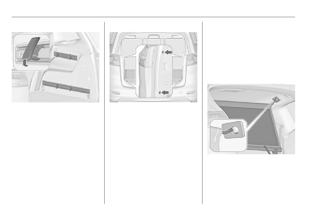
Installation of hooks in the rails
Partitioning net in front of tailgate
Safety net
The safety net can be installed behind
the seats of the second row or the
front seats.
Passengers must not be transported
behind the safety net.
Installation behind second row
seats
Insert the hook in the desired position
Install directly in front of the tailgate.
first in the upper groove of the rail and
Before installation push in the four
then press in the lower groove. To
end pieces of the net rod by rotating
remove, first pull out of the upper
each end piece anticlockwise.
groove.
To install, push the net rods together
and insert into the openings of the
tailgate frame. The longer rod must
be inserted at the top.
● There are installation openings
To remove, push the net rods
on both sides in the roof frame
together and remove.
above second row seats:
suspend and engage rod of net at
one side, compress rod and
suspend and engage at the other
side.

-------------------------------------------------------------------------------------------------------------------------------------------------------------

Storage
91
Installation behind front seats
● Attach hooks of safety net straps
to front lashing eyes on both
to the lashing eyes on both sides
● There are installation openings
sides in the load compartment.
in the floor in front of the seats.
on both sides in the roof frame
● Tension both straps by pulling at
above the front seats: suspend
the loose end.
the loose end.
and engage rod of net at one
side, compress rod and suspend
and engage at the other side.

-------------------------------------------------------------------------------------------------------------------------------------------------------------

92
Storage
Removal
Warning triangle
Insert the safety net in the storage
and close cover.
Push button on the tightener to
Stow the warning triangle in the
release the strap on both sides.
storage of the load compartment floor
Detach hooks from the eyes. Unhook
Folding tray
in front of the tailgate.
the safety net rods from the brackets
Located in the front seat backrests.
in the roof frame. Roll up the net and
Open by pulling upwards until it
First aid kit
secure with a strap.
engages.
Stow the first aid kit and the high
Stowing
Fold away by pressing down past the
visibility vest under the driver's seat.
resistance point.
Open the cover of the storage in the
load compartment floor in front of the
Do not place any heavy objects on the
tailgate.
folding tray.

-------------------------------------------------------------------------------------------------------------------------------------------------------------

Storage
93
On another version, first aid kit is
Roof rack system
located in a storage box under the
driver's seat. Slide the rollo to open or
Roof rack
close the box.
For safety reasons and to avoid
damage to the roof, the vehicle
approved roof rack system is
recommended. For further
information contact your workshop.
Follow the installation instructions
and remove the roof rack when not in
use.
Use the straps to fix.
Mounting roof rack
Vehicles with roof railing

-------------------------------------------------------------------------------------------------------------------------------------------------------------

94
Storage
Fasten the roof rack in the area of the
Do not allow the load to protrude
Loading information
holes, indicated by the arrows in the
above the upper edge of the
illustration.
backrests.
Do not place any objects on the
Vehicles without roof railing
load compartment cover or the
instrument panel.
The load must not obstruct the
operation of the pedals, parking
brake and gear selector lever, or
hinder the freedom of movement
of the driver. Do not place any
unsecured objects in the interior.
Do not drive with an open load
compartment.
Heavy objects in the load
9 Warning
compartment should be placed
against the seat backrests.
To fasten a roof rack, open the caps
Always make sure that the load in
Ensure the backrests are
in the roof strips. Insert the mounting
the vehicle is securely stowed.
securely engaged. If objects can
provisions, as instructed, in the
Otherwise objects can be thrown
be stacked, the heavier objects
retainer indicated in the illustration.
around inside the vehicle and
should be placed at the bottom.
cause personal injury or damage
Secure objects with lashing
to the load or car.
straps attached to lashing eyes
3 88.
● The payload is the difference
Secure loose objects in load
between the permitted gross
compartment to prevent sliding.
vehicle weight (see identification
plate 3 272) and the EC kerb
weight.

-------------------------------------------------------------------------------------------------------------------------------------------------------------

Storage
95
To calculate the payload, enter
the combined weight of the roof
the data for your vehicle in the
rack and the load.
weights table at the front of this
manual.
The EC kerb weight includes
weights for the driver (68 kg),
luggage (7 kg) and all fluids (fuel
tank 90% full).
Optional equipment and
accessories increase the kerb
weight.
Driving with a roof load increases
the sensitivity of the vehicle to
cross-winds and has a
detrimental effect on vehicle
handling due to the vehicle's
higher centre of gravity.
Distribute the load evenly and
secure it properly with retaining
straps. Adjust the tyre pressure
and vehicle speed according to
the load conditions. Check and
retighten the straps frequently.
Do not drive faster than 75 mph.
The permissible roof load is
75 kg for vehicles without roof
railing and 100 kg for vehicles
with roof railing. The roof load is

-------------------------------------------------------------------------------------------------------------------------------------------------------------

96
Instruments and controls
Control indicators
107
Exterior light
115
Instruments and
Turn signal
110
High beam
115
controls
Seat belt reminder
110
High beam assist
115
Airbag and belt tensioners
110
Adaptive forward lighting
115
Airbag deactivation
111
Fog light
116
Charging system
111
Rear fog light
116
Controls
97
Malfunction indicator light
111
Low washer fluid
116
Steering wheel adjustment
97
Service vehicle soon
111
Cruise control
116
Steering wheel controls
97
Brake and clutch system
111
Adaptive cruise control
116
Heated steering wheel
97
Operate pedal
112
Vehicle detected ahead
116
Horn
98
Electric parking brake
112
Door open
116
Windscreen wiper/washer
98
Electric parking brake fault
112
Information displays
116
Rear window wiper/washer
100
Antilock brake system (ABS) ... 112
Driver Information Centre
116
Outside temperature
100
Upshift
113
Graphic-Info-Display, Colour-
Clock
101
Power steering
113
Info-Display
120
Power outlets
102
Lane departure warning
113
Vehicle messages
122
Cigarette lighter
103
Ultrasonic parking assist
113
Warning chimes
125
Ashtrays
103
Electronic Stability Control off . 113
Battery voltage
126
Warning lights, gauges and indi-
Electronic Stability Control and
Traction Control system
113
Trip computer
126
cators
104
Instrument cluster
104
Traction Control system off
114
Vehicle personalisation
129
Speedometer
104
Preheating
114
OnStar
133
Odometer
104
Diesel particle filter
114
Trip odometer
104
AdBlue
114
Tachometer
104
Tyre pressure monitoring
Fuel gauge
105
system
114
Fuel selector
105
Engine oil pressure
114
Engine coolant temperature
Low fuel
115
gauge
106
Immobiliser
115
Service display
106
Reduced engine power
115

-------------------------------------------------------------------------------------------------------------------------------------------------------------

Instruments and controls
97
Controls
Steering wheel controls
Heated steering wheel
Steering wheel adjustment
The Infotainment system, some driver
Activate heating by pressing *.
assistance systems and a connected
Activation is indicated by the LED in
Unlock lever, adjust steering wheel,
mobile phone can be operated via the
the button.
then engage lever and ensure it is
controls on the steering wheel.
fully locked.
Further information is available in the
Do not adjust steering wheel unless
Infotainment manual.
vehicle is stationary and steering
Driver assistance systems 3 179.
wheel lock has been released.

-------------------------------------------------------------------------------------------------------------------------------------------------------------

98
Instruments and controls
The recommended grip areas of the
Adjustable wiper interval
Windscreen wiper/washer
steering wheel are heated quicker
and to a higher temperature than the
Windscreen wiper
other areas.
Heating is operational when the
engine is running and during an
Autostop.
Stop-start system 3 161.
Horn
Wiper lever in position INT.
Turn the adjuster wheel to adjust the
HI
: fast
desired wipe interval:
LO
: slow
short interval
: turn adjuster
INT
: interval wiping or automatic
wheel upwards
wiping with rain sensor
long interval
: turn adjuster
OFF : off
wheel downwards
For a single wipe when the
windscreen wiper is off, press the
lever down to position 1x.
Press j.
Do not use if the windscreen is frozen.
Switch off in car washes.

-------------------------------------------------------------------------------------------------------------------------------------------------------------

Instruments and controls
99
Automatic wiping with rain sensor
Adjustable sensitivity of the rain
sensor
Keep the sensor free from dust, dirt
and ice.
INT : automatic wiping with rain
sensor
Turn the adjuster wheel to adjust the
Windscreen and headlight
sensitivity:
washer
The rain sensor detects the amount of
low sensitivity
: turn adjuster
water on the windscreen and
wheel downwards
automatically regulates the frequency
high sensitivity
: turn adjuster
of the windscreen wiper.
wheel upwards
If the wiper frequency is above
20 seconds, the wiper arm moves
slightly down to the park position.

-------------------------------------------------------------------------------------------------------------------------------------------------------------

100
Instruments and controls
Pull lever. Washer fluid is sprayed
Press the rocker switch to activate the
The rear window wiper comes on
onto the windscreen and the wiper
rear window wiper:
automatically when the windscreen
wipes a few times.
wiper is switched on and reverse gear
upper position
: continuous
is engaged.
If the headlights are on, washer fluid
operation
is also sprayed onto the headlights,
lower position
: intermittent
Activation or deactivation of this
provided that the lever is pulled
operation
function can be changed in the
sufficiently long. Afterwards the
middle position
: off
Settings menu in the Info-Display.
headlight washer system is
Vehicle personalisation 3 129.
inoperable for 5 wash cycles or until
The rear window washer system is
engine or headlights have been
deactivated when the fluid level is too
switched off and on again.
low.
Rear window wiper/washer
Outside temperature
Push lever. Washer fluid is sprayed
onto the rear window and the wiper
wipes a few times.
Do not use if the rear window is
frozen.
Switch off in car washes.

-------------------------------------------------------------------------------------------------------------------------------------------------------------

Instruments and controls
101
A drop in temperature is indicated
Set time format: Changes
Clock
immediately and a rise in temperature
indication of hours between 12 h
Date and time are shown in the
after a time delay.
and 24 h.
Info-Display.
Set date format: Changes
Time and date settings
indication of date between MM/
DD/YYYY and DD.MM.YYYY.
CD 400plus/CD 400/CD 300
RDS clock synchronization: The
Press CONFIG. The menu Settings is
RDS signal of most VHF
displayed.
transmitters automatically sets
Select Time Date.
the time. RDS time
synchronisation can take a few
minutes. Some transmitters do
not send a correct time signal. In
such cases, it is recommended to
switch off automatic time
synchronisation.
If outside temperature drops to 3 °C,
Vehicle personalisation 3 129.
a warning message is displayed in the
Driver Information Centre with
Time and date settings
Uplevel-Combi-Display.
Navi 950/Navi 650/CD 600
9 Warning
Press CONFIG and then select the
Time and Date menu item to display
The road surface may already be
Selectable setting options:
the respective submenu.
icy even though the display
indicates a few degrees above 0
● Set time: Changes the time
°C.
shown on the display.
● Set date: Changes the date
shown on the display.

-------------------------------------------------------------------------------------------------------------------------------------------------------------

102
Instruments and controls
Set date
Power outlets
To adjust the time settings, select the
Set Date menu item. Turn the
multifunction knob to adjust the first
setting.
Press the multifunction knob to
confirm the input. The coloured
background moves to the next
setting.
Adjust all settings.
Time format
Notice
To choose the desired time format,
If RDS Auto Time Adjust is activated,
select 12 hr / 24 hr Format. Activate
time and date are automatically set
12 Hour or 24 Hour.
A 12 Volt power outlet is located in the
by the system.
front console. Fold the cover
Vehicle personalisation 3 129.
downwards.
See Infotainment manual for further
information.
Set time
To adjust the time settings, select the
Set Time menu item. Turn the
multifunction knob to adjust the first
setting.
Press the multifunction knob to
confirm the input. The coloured
background moves to the next
setting.
Adjust all settings.

-------------------------------------------------------------------------------------------------------------------------------------------------------------

Instruments and controls
103
Further 12 Volt power outlets are
Do not connect any current-delivering
Ashtrays
located in the rear console
accessories, e.g. electrical charging
devices or batteries.
Caution
Do not damage the outlet by using
unsuitable plugs.
To be used only for ash and not for
Stop-start system 3 161.
combustible rubbish.
Cigarette lighter
and at the left sidewall in the load
compartment.
Do not exceed the maximum power
consumption of 120 watts.
With ignition off, the power outlets are
The portable ashtray can be placed in
deactivated. Additionally the power
the cupholders.
outlets are deactivated in the event of
The cigarette lighter is located in the
low vehicle battery voltage.
front console. Fold the cover
Electrical accessories that are
downwards.
connected must comply with the
Press in cigarette lighter. It switches
electromagnetic compatibility
off automatically once the element is
requirements laid down in
glowing. Pull out lighter.
DIN VDE 40 839.

-------------------------------------------------------------------------------------------------------------------------------------------------------------

104
Instruments and controls
Trip odometer counts up to a distance
Warning lights, gauges
Odometer
of 2000 miles and then restarts at 0.
and indicators
Tachometer
Instrument cluster
In some versions, the needles of the
instruments briefly rotate to the end
position when the ignition is switched
on.
Speedometer
The bottom line displays the recorded
distance in miles.
Displays the engine speed.
Trip odometer
Drive in a low engine speed range for
The top line displays the recorded
each gear as much as possible.
distance since the last reset.
To reset, press SET/CLR on the turn
Caution
signal lever for a few seconds
3 116.
If the needle is in the red warning
Indicates vehicle speed.
Some versions are equipped with a
zone, the maximum permitted
reset knob between speedometer
engine speed is exceeded. Engine
and Driver Information Centre: to
at risk.
reset, press and hold the knob for a
few seconds with the ignition on.

-------------------------------------------------------------------------------------------------------------------------------------------------------------

Instruments and controls
105
As soon as the natural gas tank is
Fuel gauge
Fuel selector
empty, petrol operation is
Natural gas operation
automatically engaged until the
ignition is switched off.
Fuel for natural gas operation 3 209.
Liquid gas operation
Displays the fuel level or gas pressure
in the tank depending on the
operation mode.
Press Y to switch between petrol and
natural gas operation. The LED 1
Control indicator i illuminates if the
status shows the current operating
level in the tank is low. Refuel
mode.
immediately if it flashes.
Press LPG to switch between petrol
1 off
: natural gas
During liquid gas operation, the
and liquid gas operation. The LED
operation
system automatically switches over to
1 status shows the current operating
1 illumi-
: petrol operation
petrol operation when gas tanks are
mode.
nates
empty 3 105.
1 flashes
: no switching is
Never run the tank dry.
possible, one type of
Because of the fuel remaining in the
fuel is empty
tank, the top-up quantity may be less
than the specified tank capacity.

-------------------------------------------------------------------------------------------------------------------------------------------------------------

106
Instruments and controls
1 off
: petrol operation
Engine coolant temperature
Caution
1 flashes
: checking conditions
gauge
for fuel transition to
If engine coolant temperature is
liquid gas operation.
too high, stop vehicle, switch off
Illuminates if
engine. Danger to engine. Check
conditions are fulfilled.
coolant level.
1 illumi-
: liquid gas operation
nates
1 flashes 5
: liquid gas tank is
Service display
times and
empty or failure in
The engine oil life system lets you
extin-
liquid gas system. A
know when to change the engine oil
guishes
message is displayed
and filter. Based on driving
in the Driver
conditions, the interval at which an
Information Centre.
engine oil and filter change will be
indicated can vary considerably.
As soon as the liquid gas tank is
empty, petrol operation is
Displays the coolant temperature.
automatically engaged until the
left area
: engine operating
ignition is switched off.
temperature not yet
Fuel for liquid gas operation 3 210.
reached
central
: normal operating
area
temperature
right area
: temperature too high


Content      ..     4      5      6      7     ..