Vauxhall ADAM (2012 year). Manual - part 11


  Index      Vauxhall     Vauxhall ADAM (2012 year) - manual in english


Search            copyright infringement  


Content      ..     9      10      11      12     ..


Vauxhall ADAM (2012 year). Manual - part 11


-------------------------------------------------------------------------------------------------------------------------------------------------------------
Vehicle care
175
4. Remove bulb by turning
4. Insert bulb holder and turn
anticlockwise slightly and
clockwise.
withdrawing. Replace the bulb.
5. Insert left end of the lamp, slide to
5. Insert the bulb socket into the
the left and insert right end.
assembly and turn clockwise.
6. Attach light assembly into the
Number plate light
bumper and fix with both screws.
7. Insert and engage cover into the
bumper.
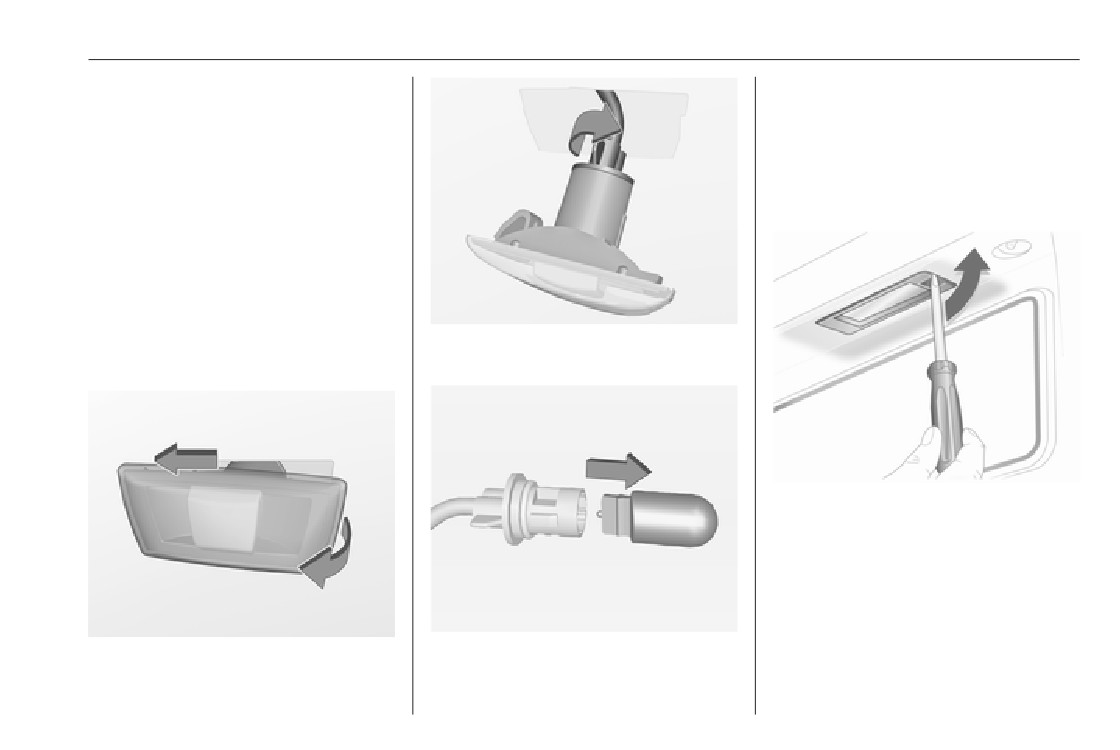
Side turn signal lights
To replace bulb, remove lamp
2. Turn bulb holder anticlockwise
housing:
and remove from housing.
1. Insert screwdriver in recess of the
cover, press to the side and
release spring.
3. Pull bulb from bulb holder and
1. Slide lamp to its left side and
replace it.
remove with its right end.

-------------------------------------------------------------------------------------------------------------------------------------------------------------

176
Vehicle care
4. Pull bulb from bulb holder and
Instrument panel
replace it.
illumination
5. Insert bulb holder into lamp
Have bulbs replaced by a workshop.
housing and turn clockwise.
6. Insert lamp into bumper and allow
it to engage.
Interior lights
Courtesy light, reading lights
Have bulbs replaced by a workshop.
2. Remove lamp downwards, taking
care not to pull on the cable.
Load compartment light
Have bulbs replaced by a workshop.
Dome light
Have bulbs replaced by a workshop.
Ambient light
Have bulbs replaced by a workshop.
Starlight panel
Have bulbs replaced by a workshop.
3. Remove bulb holder from lamp
housing by turning anticlockwise.

-------------------------------------------------------------------------------------------------------------------------------------------------------------

Vehicle care
177
There are different kinds of fuses in
Electrical system
the vehicle.
Fuses
Data on the replacement fuse must
match the data on the defective fuse.
There are two fuse boxes in the
vehicle:
● in the front left of the engine
compartment,
● in left-hand drive vehicles behind
the light switch, or, in right-hand
drive vehicles, behind the
Place the fuse extractor on the
glovebox.
various types of fuse from the top, and
withdraw fuse.
Before replacing a fuse, turn off the
Depending on the type of fuse, a
respective switch and the ignition.
blown fuse can be recognized by its
melted wire. Do not replace the fuse
until the cause of the fault has been
remedied.
Some functions are protected by
several fuses.
Fuses may also be inserted without
existence of a function.
Fuse extractor
A fuse extractor may be located in the
fuse box in the engine compartment.

-------------------------------------------------------------------------------------------------------------------------------------------------------------

178
Vehicle care
Engine compartment fuse
No. Circuit
box
1
-
2
Exterior mirror switch
3
Body control module
4
Foldable sunroof/Chassis
control module
5
ABS
6
Daytime running light left
7
-
8
Body control module
The fuse box is in the front left of the
9
Vehicle battery sensor
engine compartment.
10
Headlamp levelling/TPMS/
Disengage the cover and fold it
Foldable sunroof
upwards until it stops. Remove the
cover vertically upwards.
11
Rear wiper
12
Window defog
13
Daytime running light right
14
Mirror defog
15
-

-------------------------------------------------------------------------------------------------------------------------------------------------------------

Vehicle care
179
No. Circuit
No. Circuit
16
Chassis control module/LPG
32
Right headlamp
system
33
Engine control module
17
Interior mirror
34
Horn
18
Engine control module
35
Clutch
19
Fuel pump
36
-
20
-
21
Injection coil
22
-
23
Injection system
24
Washer system
25
Lighting system
26
Engine control module
27
-
28
Engine control module
29
Engine control module
30
-
31
Left headlamp

-------------------------------------------------------------------------------------------------------------------------------------------------------------

180
Vehicle care
No. Circuit
Instrument panel fuse box
1
ABS pump
2
Front wiper
3
Blower
4
Instrument panel
5
-
6
-
7
Electrical vacuum pump
8
Cooling fan low
9
Cooling fan high
The fuse box is located behind a
cover in the glovebox. Open the
10
Cooling fan/Electrical vacuum
glovebox, then open the cover and
pump
fold it down.
11
Starter
After having changed defective fuses
close the fuse box cover and press
until it engages.
If the fuse box cover is not closed
correctly, malfunction may occur.

-------------------------------------------------------------------------------------------------------------------------------------------------------------

Vehicle care
181
No.
Circuit
No.
Circuit
No.
Circuit
1
-
18
Air conditioning system
35
-
2
-
19
Audio amplifier
36
-
3
Power windows
20
Parking assist
37
Rear wiper
4
Voltage transformer
21
Brake switch
38
Cigarette lighter
5
Body control module 1
22
Audio system
39
-
6
Body control module 2
23
Display
40
-
7
Body control module 3
24
-
8
Body control module 4
25
Onstar
9
Body control module 5
26
Instrument panel
10
Body control module 6
27
Seat heating, driver
11
Body control module 7
28
-
12
Body control module 8
29
-
13
-
30
Instrument panel
14
Tailgate
31
Horn
15
Diagnostic connector
32
Seat heating, passenger
16
Data link connection
33
Heated steering wheel
17
Ignition
34
-

-------------------------------------------------------------------------------------------------------------------------------------------------------------

182
Vehicle care
Vehicle tools
Tools
Vehicles with tyre repair kit
On versions with rear carrier system
On version with storage box, the
or liquid gas engine, the tools are
suitcase with the tools, the towing eye
located together with the towing eye
and the tyre repair kit is located in a
and tyre repair kit in a suitcase, fixed
chamber of the box in the load
with a strap at the left sidewall in the
compartment 3 63.
load compartment.
Some tools and the towing eye are
located together with the tyre repair
kit in a tool box in the load
compartment below the floor cover.
On version with storage box, remove
box first 3 63.

-------------------------------------------------------------------------------------------------------------------------------------------------------------

Vehicle care
183
On version with subwoofer box, the
In accordance with country-specific
Wheels and tyres
tools and the towing eye are located
regulations, affix the speed sticker in
together with the tyre repair kit and
the driver's field of view.
the warning triangle in the box below
Tyre condition, wheel condition
the floor cover. To gain access,
Drive over edges slowly and at right
Tyre designations
remove floor cover: fold rear part to
angles if possible. Driving over sharp
E.g. 195/55 R 16 95 H
the front and pull out the cover to the
edges can cause tyre and wheel
rear 3 64.
195 : tyre width, mm
damage. Do not trap tyres on the kerb
55
: cross-section ratio (tyre height
Vehicles with spare wheel
when parking.
to tyre width), %
Regularly check the wheels for
R
: belt type: Radial
damage. Seek the assistance of a
RF : type: RunFlat
workshop in the event of damage or
16
: wheel diameter, inches
unusual wear.
95
: load index e.g. 95 is equivalent
We recommend not swapping the
to 690 kg
front wheels with the rear wheels and
H
: speed code letter
vice versa, as this can affect vehicle
Speed code letter:
stability. Always use less worn tyres
on the rear axle.
Q : up to 100 mph
S : up to 112 mph
T
: up to 118 mph
Winter tyres
H : up to 130 mph
Winter tyres improve driving safety at
V : up to 150 mph
The jack, the wheel bolt wrench, the
temperatures below 7 °C and should
W : up to 168 mph
tools and two straps for securing a
therefore be fitted on all wheels.
Choose a tyre appropriate for the
damaged wheel are in the tool box
All tyre sizes are permitted as winter
maximum speed of your vehicle.
below the load compartment floor
tyres 3 223.
cover 3 64.
Tyre size 185/60 R 15 is only
permitted as winter tyre.

-------------------------------------------------------------------------------------------------------------------------------------------------------------

184
Vehicle care
The maximum speed is achievable at
The tyre pressure tables show all
kerb weight with driver (75 kg) plus
possible tyre combinations 3 223.
125 kg payload. Optional equipment
Identify the respective tyre.
could reduce the maximum speed of
For the tyres approved for your
the vehicle.
vehicle, refer to the EEC Certificate of
Performance 3 219.
Conformity provided with your vehicle
or other national registration
Directional tyres
documents.
Directional tyres must be mounted so
The driver is responsible for correct
that they rotate in the correct
adjustment of tyre pressure.
direction. The proper rotation
direction is indicated by a symbol
9 Warning
(e.g. an arrow) on the sidewall.
Tyre pressure 3 223.
The tyre pressure information label
If the pressure is too low, this can
on the right door frame indicates the
result in considerable tyre warm-
Tyre pressure
original equipment tyres and the
up and internal damage, leading to
Check the pressure of cold tyres at
correspondent tyre pressures.
tread separation and even to tyre
least every 14 days and before any
The tyre pressure data refers to cold
blow-out at high speeds.
long journey. Do not forget the spare
tyres. It applies to summer and winter
wheel.
tyres.
This also applies to vehicles with tyre
9 Warning
The ECO tyre pressure serves to
pressure monitoring system.
achieve the smallest amount of fuel
For specific tyres the
Unscrew the valve cap.
consumption possible.
recommended tyre pressure as
Incorrect tyre pressures will impair
shown in the tyre pressure table
safety, vehicle handling, comfort and
may exceed the maximum tyre
fuel economy and will increase tyre
pressure as indicated on the tyre.
wear.
Never exceed the maximum tyre
pressure as indicated on the tyre.

-------------------------------------------------------------------------------------------------------------------------------------------------------------

Vehicle care
185
If the tyre pressure must be reduced
The menu can be selected by
Tyre pressure monitoring
or increased, switch off ignition. After
pressing the buttons on the turn
system
adjusting tyre pressure switch on
signal lever.
ignition and select the relevant setting
The tyre pressure monitoring system
on the page Tyre load in the Driver
checks the pressure of all four tyres
Information Centre 3 88.
once a minute when vehicle speed
exceeds a certain limit.
Temperature dependency
Caution
The tyre pressure depends on the
temperature of the tyre. During
Tyre pressure monitoring system
driving, tyre temperature and
warns only about low tyre pressure
pressure increase. Tyre pressure
condition and does not replace
values provided on the tyre
regular tyre maintenance by the
information label and tyre pressure
driver.
chart are valid for cold tyres, which
means at 20 °C.
All wheels must be equipped with
Press MENU to select the Vehicle
The pressure increases by nearly
pressure sensors and the tyres must
Information MenuX
1.5 psi for a 10 °C temperature
have the prescribed pressure.
increase. This must be considered
when warm tyres are checked.
Notice
In countries where the tyre pressure
The tyre pressure value displayed in
monitoring system is legally
the Driver Information Centre shows
required, the use of wheels without
the real tyre pressure. A cooled down
pressure sensors will invalidate the
tyre will show a decreased value,
vehicle type approval.
which does not indicate an air leak.
The current tyre pressures can be
shown in the Vehicle Information
Menu in the Driver Information
Centre.

-------------------------------------------------------------------------------------------------------------------------------------------------------------

186
Vehicle care
If w illuminates at lower temperatures
and extinguishes after some driving,
this could be an indicator for
approaching a low tyre pressure
condition. Check tyre pressure.
Vehicle messages 3 95.
If the tyre pressure must be reduced
or increased, switch off ignition.
Only mount wheels with pressure
sensors, otherwise the tyre pressure
will not be displayed and w
illuminates continuously.
Turn the adjuster wheel to select the
A detected low tyre pressure
A spare wheel or temporary spare
tyre pressure monitoring system.
condition is indicated by the control
wheel is not equipped with pressure
indicator w 3 87.
System status and pressure warnings
sensors. The tyre pressure
are displayed by a message with the
If w illuminates, stop as soon as
monitoring system is not operational
corresponding tyre flashing in the
possible and inflate the tyres as
for these tyres. Control indicator w
Driver Information Centre.
recommended 3 223.
illuminates. For the further three
The system considers the tyre
If w flashes for 60-90 seconds then
tyres, the system remains
temperature for the warnings.
illuminates continuously, there is a
operational.
Temperature dependency 3 184.
fault in the system. Consult a
The use of commercially-available
workshop.
liquid tyre repair kits can impair the
After inflating, some driving may be
function of the system. Factory-
required to update the tyre pressure
approved repair kits can be used.
values in the Driver Information
Operating electronic devices or being
Centre. During this time w may
close to facilities using similar wave
illuminate.
frequencies could disrupt the tyre
pressure monitoring system.

-------------------------------------------------------------------------------------------------------------------------------------------------------------

Vehicle care
187
Each time the tyres are replaced, tyre
matching process should also be
pressure monitoring system sensors
performed after replacing a spare tyre
must be dismounted and serviced.
with a road tyre containing the TPMS
For the screwed sensor; replace
sensor.
valve core and sealing ring. For the
The malfunction light w and the
clipped sensor; replace complete
warning message or code should go
valve stem.
off at the next ignition cycle. The
sensors are matched to the wheel
Vehicle loading status
positions, using a relearn tool, in the
Adjust tyre pressure to load condition
following order: left side front wheel,
according to the tyre information label
right side front wheel, right side rear
or tyre pressure chart 3 223, and
wheel and left side rear wheel. The
select the appropriate setting in the
turn signal light at the current active
Select:
menu Tyre Load in the Driver
position is illuminated until sensor is
● Light for comfort pressure up to
Information Centre, Vehicle
matched.
3 people.
Information Menu 3 88. This setting is
Consult a workshop for service or
the reference for the tyre pressure
● Eco for Eco pressure up to
purchase a relearn tool. There are
warnings.
3 people.
two minutes to match the first wheel
The Tyre Load menu only appears if
● Max for full loading.
position, and five minutes overall to
the vehicle is in a standstill and the
match all four wheel positions. If it
Tyre pressure sensor matching
parking brake is applied. On vehicles
takes longer, the matching process
with automatic transmission the
process
stops and must be restarted.
selector lever has to be in P.
Each TPMS sensor has a unique
The tyre pressure sensor matching
identification code. The identification
process is:
code must be matched to a new tyre/
1. Apply the parking brake.
wheel position after rotating the tyres
2. Turn the ignition on.
or exchanging the complete wheel set
and if one or more TPMS sensors
3. On vehicles with manual
were replaced. The TPMS sensor
transmission automated: Press

-------------------------------------------------------------------------------------------------------------------------------------------------------------

188
Vehicle care
and hold brake pedal. Move and
the tyre pressure sensor. A horn
Tread depth
hold the selector lever for five
chirp confirms that the sensor
Check tread depth at regular
seconds in position N until P is
identification code has been
intervals.
displayed in the Driver
matched to this wheel position.
Information Centre. P indicates
Tyres should be replaced for safety
10. Proceed to the right side front
that the sensor matching process
reasons at a tread depth of 2-3 mm
wheel, and repeat the procedure
can be started.
(4 mm for winter tyres).
in Step 9.
On vehicles with manual
For safety reasons it is recommended
11. Proceed to the right side rear
transmission: select neutral.
that the tread depth of the tyres on
wheel, and repeat the procedure
one axle should not vary by more than
4. Use MENU on the turn signal
in Step 9.
2 mm.
lever to select the Vehicle
12. Proceed to the left side rear
Information Menu in the Driver
wheel, and repeat the procedure
Information Centre.
in Step 9. The horn sounds twice
5. Turn the adjuster wheel to scroll to
to indicate that the sensor
the tyre pressure menu.
identification code has been
matched to the left side rear
6. Press SET/CLR to begin the
wheel, and the tyre pressure
sensor matching process. A
sensor matching process is no
message requesting acceptance
longer active.
of the process should be
displayed.
13. Turn off the ignition.
7. Press SET/CLR again to confirm
14. Set all four tyres to the
the selection. The horn sounds
recommended air pressure level
twice to indicate that the receiver
as indicated on the tyre
is in relearn mode.
information label.
The legally permissible minimum
tread depth (1.6 mm) has been
8. Start with the left side front wheel.
15. Ensure the tyre loading status is
reached when the tread has worn
set according to the selected
9. Place the relearn tool against the
down as far as one of the tread wear
pressure 3 88.
tyre sidewall, near the valve stem.
Then press the button to activate

-------------------------------------------------------------------------------------------------------------------------------------------------------------

Vehicle care
189
indicators (TWI). Their position is
Steel wheels: When using locking
9 Warning
indicated by markings on the
wheel bolts, do not attach wheel
sidewall.
covers.
Use of unsuitable tyres or wheels
Tyres age, even if they are not used.
may lead to accidents and will
We recommend tyre replacement
invalidate the vehicle type
Tyre chains
every 6 years.
approval.
Changing tyre and wheel
Wheel covers
size
Wheel covers and tyres that are
If tyres of a different size than those
factory approved for the respective
fitted at the factory are used, it may be
vehicle and comply with all of the
necessary to reprogramme the
relevant wheel and tyre combination
speedometer as well as the nominal
requirements must be used.
tyre pressure and to make other
If the wheel covers and tyres used are
vehicle modifications.
not factory approved, the tyres must
After converting to a different tyre
not have a rim protection ridge.
size, have the label with tyre
Wheel covers must not impair brake
pressures replaced.
cooling.
Tyre chains are only permitted on the
front wheels.
Caution
9 Warning
Always use fine mesh chains that add
no more than 10 mm to the tyre tread
When converting to wheels with
Use of unsuitable tyres or wheel
and the inboard sides (including chain
14'', the ground clearance will be
covers could lead to sudden
lock).
reduced. This must be considered
pressure loss and thereby
when passing over obstacles.
accidents.
9 Warning
Damage may lead to tyre blowout.

-------------------------------------------------------------------------------------------------------------------------------------------------------------

190
Vehicle care
Tyre chains are only permitted on
Apply the parking brake and engage
tyres of size 175/70 R 14,
first gear.
185/70 R 14, 185/60 R 15,
185/65 R 15 and 195/55 R 16.
Tyre chains are not permitted on tyres
of size 215/45 R 17 and 225/35 R 18.
The use of tyre chains is not permitted
on the temporary spare wheel.
Tyre repair kit
Minor damage to the tyre tread can be
repaired with the tyre repair kit.
On versions with rear carrier system
Do not remove foreign bodies from
or liquid gas engine, the tyre repair kit
the tyres.
is located in a suitcase and fixed with
The tyre repair kit is in the tool box
a strap at the left sidewall in the load
Tyre damage exceeding 4 mm or that
under the floor cover in the load
compartment.
is at the tyre's sidewall cannot be
compartment.
repaired with the tyre repair kit.
9 Warning
Do not drive faster than 50 mph.
Do not use for a lengthy period.
Steering and handling may be
affected.
If you have a flat tyre:

-------------------------------------------------------------------------------------------------------------------------------------------------------------

Vehicle care
191
On versions with storage box in the
3. Remove the electrical connection
load compartment the suitcase with
cable and air hose from the
the tyre repair kit is located in a
stowage compartments on the
chamber of the box 3 63.
underside of the compressor.
1. Take the tyre repair kit from the
compartment.
2. Remove the compressor.
4. Screw the compressor air hose to
On versions with subwoofer box the
the connection on the sealant
tyre repair kit is located in the box
bottle.
under the floor cover in the load
compartment. To use tyre repair kit,
5. Fit the sealant bottle into the
firstly remove floor cover: fold rear
retainer on the compressor.
part to the front and pull out the cover
Set the compressor near the tyre
to the rear 3 64.
in such a way that the sealant
bottle is upright.


Content      ..     9      10      11      12     ..