Snowmobile Arctic Cat 2-Stroke (2007 year). Manual - part 142


  Index      Snowmobiles / ATV     Snowmobile Arctic Cat 2-Stroke - service manual 2007 year


Search            


Content   ..  140  141  142  143   ..


Snowmobile Arctic Cat 2-Stroke (2007 year). Manual - part 142


9-81

9

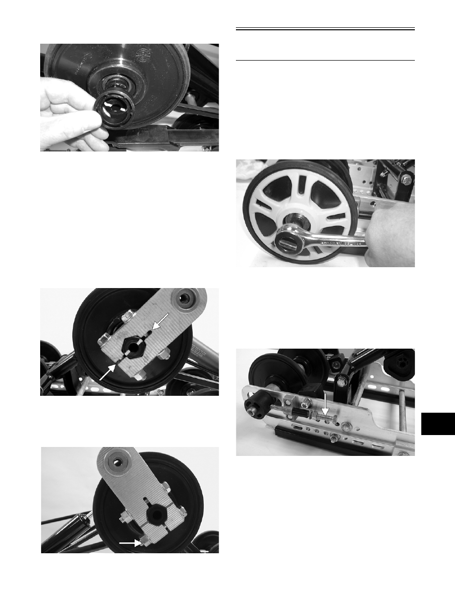
4. Install the idler spacer collar onto the idler arm.

MS064

„NOTE: Steps 5 and 6 are for the Crossfire models.

5. Place the flared bushing with a thin flat washer

through the notched side of the offset pivot idler

arm assembly.

„NOTE: If the flared bushing in the offset pivot idler
arm is loose, it must be cleaned and green Loctite
#609 must be applied to it prior to installation.

6. Align the marks on the idler arm to the centerline

of the offset pivot idler arm assembly. Secure the

offset pivot idler arm to the idler arm with cap

screws and lock nuts. Tighten to specifications.

MS146A

„NOTE: When tightening the pivot idler arm lock
nuts, tighten the lower lock nut first or binding may
occur.

MS019B

Rear Axle and

Idler Wheels

„NOTE: The skid frame must be removed for this
procedure (see Removing Skid Frame in this sub-
section).

DISASSEMBLING

1. Remove the cap screw and large flat washer secur-

ing the outer rear idler wheel. Remove the outer

idler wheel from the shaft.

FC194

„NOTE: The large flat side of the wheel insert is
positioned next to the inner plastic adjuster bush-
ing. The idler wheel must be installed with the
wheel insert properly positioned.

2. Loosen the track adjusting bolts. Slide the outer

adjuster bushings off the axle.

MS147A

9-82

MS148

3. Carefully slide the shaft out from the slide rails

and note the position of the spacers and washers.

CLEANING AND INSPECTING

„NOTE: Whenever a part is worn excessively,
cracked, or damaged in any way, replacement is
necessary.

1. Clean the bearings with a clean cloth.

2. Inspect all idler wheel inserts (inner and outer) for

any cracks.

3. Inspect the outer rubber portion of the idler wheels

for cracks and poor bonding.

4. Inspect the plastic insert of each idler wheel for

cracks.

5. Inspect the shaft for wear and damaged threads.

6. Inspect all idler wheel bearings. Turn each bearing

(by hand) and if any roughness or binding is noted,

replace the bearing.

7. If a bearing must be replaced, use this procedure.

A. Remove the wheel insert (if applicable) and the

snap ring.

B. Using a hydraulic press, press the bearing out

the inside of the wheel.

C. Press the new bearing (on its outer race) into

the idler wheel.

MS006A

D. Install the snap ring making sure the “sharp

side” is directed away from the bearing.

MS007A

E. Install the insert (if applicable).

MS008

ASSEMBLING

1. In order from one side, slide the axle through the

slide rail; then place a flat washer, short spacer

with bushings, inner idler wheels with inserts (if

applicable), long spacer with bushings, and flat

washer on the axle. Slide the axle through the

opposite slide rail axle bracket. Place the plastic

adjuster bushings on the axle (on the outside of

each axle bracket). Make sure the hole in the

adjuster bushing is aligned directly with the

adjusting bolt.

! CAUTION

Do not remove the bearing unless it is absolutely
necessary. The bearing will be damaged during
removal.

9-83

9

MS150

MS151A

2. Place the outer idler wheels on the axle and secure

with two cap screws (coated with blue Loctite

#243) and large flat washers. Tighten cap screws

only until snug.

MS152

„NOTE: It is advisable to tighten the rear idler
wheel axle only until snug until the skid frame has
been installed and track tension has been
adjusted; then the axle assembly must be tight-
ened to specifications.

3. Install the skid frame (see Installing Skid Frame in

this sub-section).

4. Adjust track alignment (see Track Alignment in

this sub-section).

5. Adjust track tension deflection (see Track Tension

in this sub-section).

Rear Arm/Idler Arm

„NOTE: The skid frame must be removed for this
procedure (see Removing Skid Frame in this sub-
section).

DISASSEMBLING

1. Remove the rear upper idler wheels and springs

(see Rear Upper Idler Wheels/Rear Springs in this

sub-section).

MS153

2. Remove the cap screw and lock nut securing the

upper shock eyelet to the idler arm. Account for a

spacer, cap screw, and lock nut.

MS154A

„NOTE: Mark the hole that the upper shock links
are mounted in for assembly purposes.

MS155

9-84

3. Remove the cap screw and lock nut securing the

upper shock links to the idler arm. Account for a

cap screw, lock nut, spacer, and axle links.

MS156A

MS031

4. Remove the cap screw and lock nut securing the

rear arm to the slide rail. Account for the serrated

axles and axle tube.

ZJ268A

„NOTE: To remove the rear arm, it may be neces-
sary to loosen the rear arm limiter.

ZJ269A

MS028

5. Remove the cap screw and lock nut securing the

rear arm to the idler arm. Account for the alumi-

num axle and bushing assemblies.

MS029A

MS030


Content   ..  140  141  142  143   ..