Snowmobile Arctic Cat 2-Stroke (2007 year). Manual - part 140


  Index      Snowmobiles / ATV     Snowmobile Arctic Cat 2-Stroke - service manual 2007 year


Search            


Content   ..  138  139  140  141   ..


Snowmobile Arctic Cat 2-Stroke (2007 year). Manual - part 140


9-73

9

FS249A

3. Place a support stand under the rear bumper; then

while holding the flared bushing, remove the rear

cap screws securing the skid frame to the tunnel.

Account for lock washers and flat washers.

„NOTE: The support stand should hold the snow-
mobile level but not raised off the floor.

4. Remove the front cap screws securing the skid

frame to the tunnel. Account for a flat washer and

a lock washer.

5. Remove the support stand; then tip the snow-

mobile onto one side using a piece of cardboard to

protect against scratching. Remove the skid frame.

MS132

Wear Strips

REMOVING

„NOTE: The skid frame does not have to be
removed for this procedure; however, if wear strip
binding or slide rail damage has occurred, the skid
frame should be removed for this procedure (see
Removing Skid Frame in this sub-section).

1. Remove the machine screw and lock nut securing

the wear strip to the front of the slide rail.

MS016B

„NOTE: If the skid frame has been removed due to
difficulty in removing the wear strip, it may be nec-
essary to use a pipe wrench, start from either end,
and hook the edge of the wear strip with the pipe
wrench jaw and twist the wear strip off the slide
rail. Move the pipe wrench 7.5 cm (3 in.) and again
twist the wear strip off the rail. Repeat this proce-
dure until the wear strip is free of the rail.

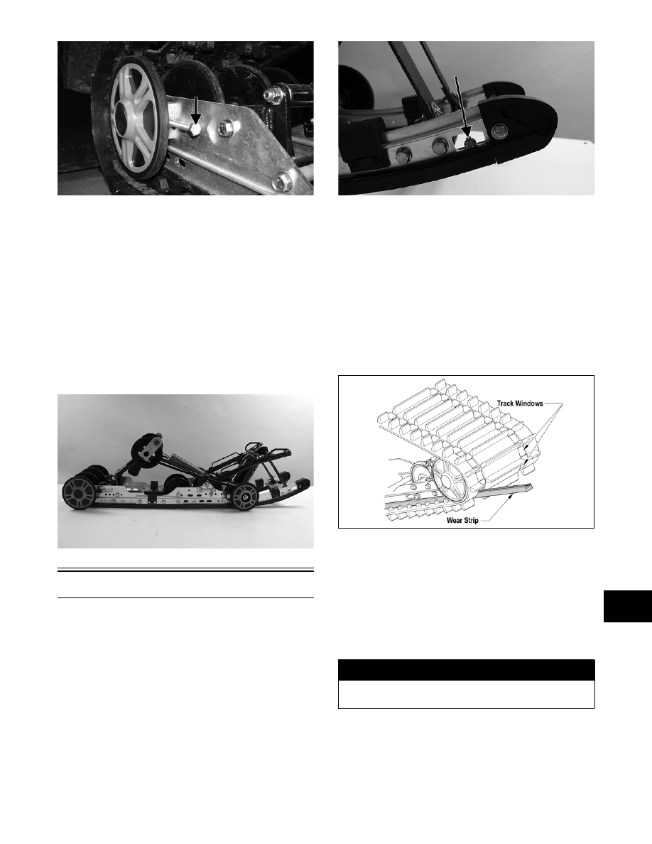
2. Align the wear strip with the openings (windows)

in the track; then using a suitable driving tool,

drive the wear strip rearward off the slide rail.

739-884A

CLEANING AND INSPECTING

„NOTE: Whenever a part is worn excessively,
cracked, or damaged in any way, replacement is
necessary.

1. Clean the slide rail using parts-cleaning solvent

and compressed air.

2. Inspect the slide rail for cracks. If any cracks are

found, replace the slide rail.

! WARNING

Always wear an approved pair of safety glasses
when using compressed air.

9-74

3. Using a straightedge, inspect the slide rail for any

unusual bends. With the slide rail removed, place

the straightedge along the bottom surface of the

slide rail. If the rail is found to be bent, it must be

replaced.

AG536D

INSTALLING

„NOTE: Apply a light coat of grease to the slide
rail surface to aid in installing a new wear strip. If
there are any sharp edges on the lower portion of
the rail, use a file to remove them.

1. Align the wear strip with the openings (windows)

in the track and from the back, start the wear strip

onto the rail; then using a block of wood and a

hammer, drive the wear strip forward into posi-

tion.

739-884A

2. Secure with a machine screw and lock nut. Tighten

to specifications.

End Caps

„NOTE: The skid frame does not have to be
removed for this procedure.

REMOVING

1. Remove the lock nut, washers, and cap screw

securing the end cap.

MS016A

2. Using a hammer, tap the end cap off the rail.

CLEANING AND INSPECTING

„NOTE: Whenever a part is worn excessively,
cracked, or damaged in any way, replacement is
necessary.

1. Inspect the end cap area of the slide rail for cracks

and wear.

MS017A

2. Inspect the end cap for any signs of cracking or

wear.

MS290A

3. Clean both the slide rail area and the end cap.

Using compressed air, clean the areas of dirt and

gravel.

! WARNING

Always wear an approved pair of safety glasses
when using compressed air.

9-75

9

4. Inspect the cap screw for cracked, stretched, or

damaged threads. Use a new lock nut when assem-

bling.

INSTALLING

1. Position the end cap on the slide rail; then align the

hole in the end cap with the hole in the slide rail.

2. Secure with a cap screw, washers, and lock nut.

Tighten to specifications.

Shock Pads

„NOTE: The skid frame does not have to be
removed for this procedure.

REMOVING

„NOTE: The shock pads should be removed only if
being replaced.

1. Using a 3/16-in. drill bit, drill out the rivets secur-

ing the front shock pads to the slide rail. Account

for the retaining brackets.

2. Twist the push nuts off the solid rivets securing the

rear shock pads.

3. Remove the shock pads.

INSPECTING

„NOTE: Whenever a part is worn excessively,
cracked, or damaged in any way, replacement is
necessary.

1. Inspect the pads for damage or wear.

2. Inspect the rivet holes in the slide rail for damage

or elongation.

INSTALLING

1. Place the rear pads into position on the slide rail.

2. Secure the rear pads with new push nuts.

3. Place the front pads and retaining brackets into

position on the slide rail.

4. Secure the front pads with rivets.

Front Outer 

Idler Wheels

„NOTE: The skid frame does not have to be
removed for this procedure.

REMOVING

1. Remove the cap screw and lock nut securing the

front outer idler wheel and the idler wheel mount-

ing block.

MS133A

MS134A

2. Account for flat washers and spacers.

CLEANING AND INSPECTING

„NOTE: Whenever a part is worn excessively,
cracked, or damaged in any way, replacement is
necessary.

1. Clean the bearing with a clean cloth.

2. Inspect each idler wheel and each plastic hub for

cracks or damage.

3. Rotate the idler wheel bearing (by hand) and

inspect for binding or roughness.

4. If a bearing must be replaced, use this procedure.

A. Remove the wheel insert (if applicable) and the

snap ring.

B. Using a hydraulic press, press the bearing out

the inside of the wheel.

! CAUTION

Do not remove the bearing unless it is absolutely
necessary. The bearing will be damaged during
removal.

9-76

C. Press the new bearing (on its outer race) into

the idler wheel.

MS006A

D. Install the snap ring making sure the “sharp

side” is directed away from the bearing.

MS007A

E. Install the insert (if applicable).

MS008

INSTALLING

1. Secure the mounting block on the slide rail with a

cap screw and lock nut. Tighten to specifications.

„NOTE: For proper alignment, it is advisable to
install an idler wheel cap screw into the top mount-
ing block hole prior to tightening.

MS009A

2. Place the idler wheel to the mounting block; then

secure the idler wheel assembly with a cap screw,

flat washer, and a lock nut. Tighten to specifica-

tions.

MS136

Rear Inner Idler Wheels

„NOTE: The skid frame does not have to be
removed for this procedure.

REMOVING

1. Remove the cap screws, washers, and lock nuts

securing the rear inner idler wheel and the idler

wheel mounting block. Account for all mounting

hardware.

MS137

2. Note the locations of the flat washer for assembly

purposes.


Content   ..  138  139  140  141   ..