Snowmobile Arctic Cat 2-Stroke (2007 year). Manual - part 118
8-92
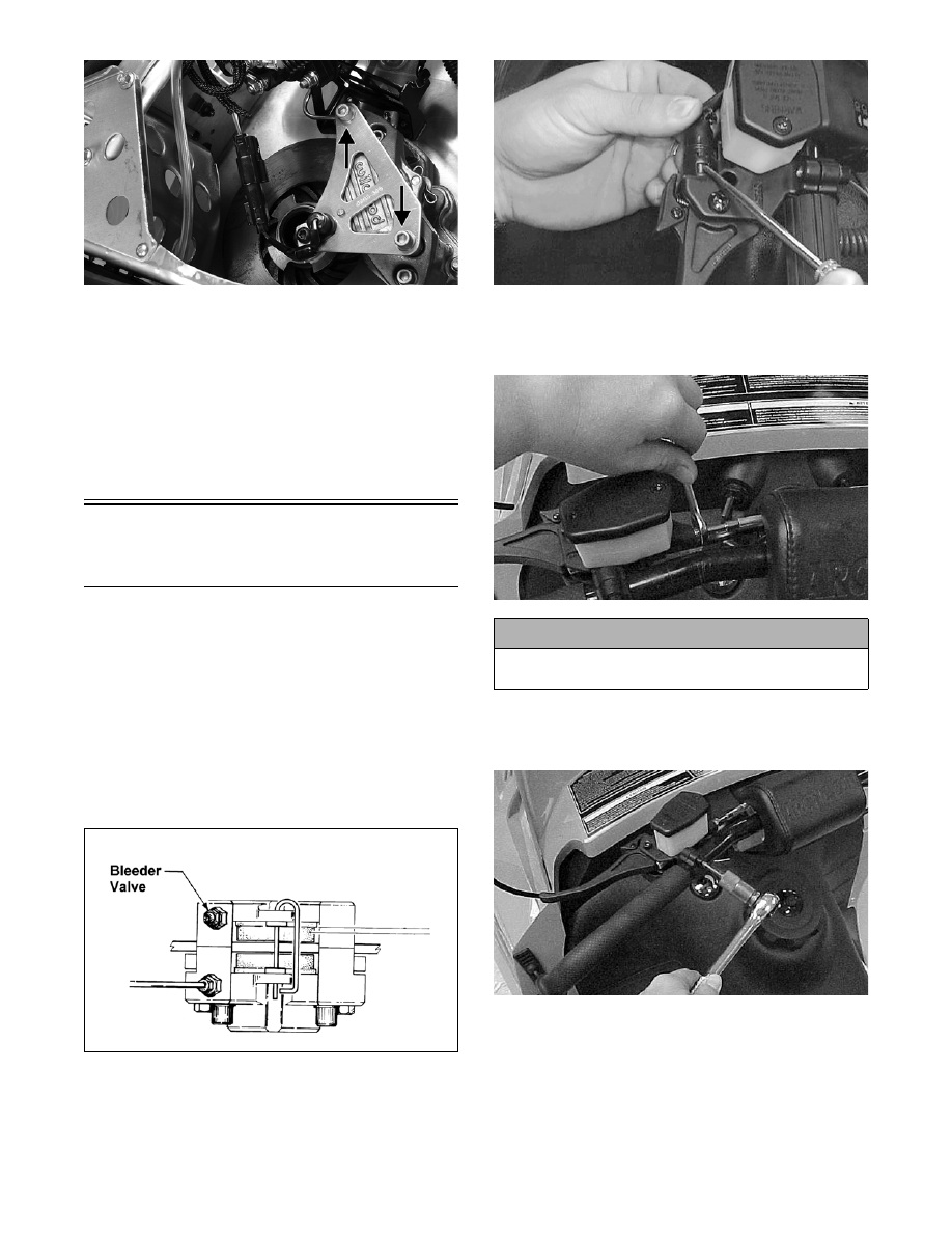
ZJ210A
15. Connect the harness connector to the speedometer
sensor plug-in.
16. Install the toe shield and toe hook bracket; then
install the torx-head cap screws. Tighten securely.
17. Place the expansion chamber and resonator into
position and secure with the springs and the hair-
pin clip.
18. Adjust track alignment and tension (see Section 9).
Brake Lever/Master
Cylinder Assembly
(Hydraulic System - STD)
NOTE: If servicing the Panther 570, see Brake
Lever/Master Cylinder Assembly (ACT/Panther
570) in this section.
REMOVING
1. Slide a piece of flexible tubing over the ball of the
bleeder valve and direct the other end into a con-
tainer. Remove the reservoir cover; then open the
bleeder valve. Allow the brake fluid to drain com-
pletely.
730-434H
2. To remove the switch, use a small screwdriver to
compress the plastic locking tabs by pushing in on
the tabs; then slide the switch free of the brake
control.
AF201D
3. Place an absorbent towel around the connection to
absorb brake fluid. Remove the brake fluid hose
from the master cylinder.
FC258
4. Remove the two torx-head screws and clamp
securing the brake assembly to the handlebar; then
remove the assembly from the handlebar.
FC259
DISASSEMBLING
1. Remove the screw and lock nut securing the brake
lever.
STD
! CAUTION
Brake fluid is highly corrosive. Do not spill brake
fluid on any surface of the snowmobile.