Snowmobile Arctic Cat 2-Stroke (2007 year). Manual - part 117


  Index      Snowmobiles / ATV     Snowmobile Arctic Cat 2-Stroke - service manual 2007 year


Search            


Content   ..  115  116  117  118   ..


Snowmobile Arctic Cat 2-Stroke (2007 year). Manual - part 117


8-88

ZJ230

ZJ251A

Cleaning and Inspecting

„NOTE: Whenever a part is worn excessively,
cracked, or damaged in any way, replacement is
necessary.

1. Inspect the brake pistons for gouges, cracks, pit-

ting, scuffing, or corrosion. If any of these condi-

tions exist, replace the piston.

„NOTE: The inner and outer caliper housings are
not serviceable components. If either or both are
defective or damaged, the complete caliper assem-
bly must be replaced. 

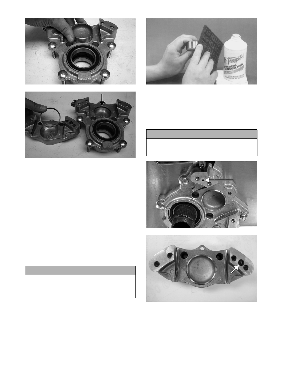
2. Clean the piston outer surface by using a soft

Scotch-Brite pad and clean brake fluid as a

cleaner.

AF230

3. Inspect the piston bore of the inner and outer brake

calipers for gouges, cracks, pitting, scuffing, or

corrosion. If any of these conditions exist, replace

the caliper.

4. Clean the caliper inner wall surface using a soft

lint-free cloth and clean brake fluid.

ZJ225A

MS320A

5. Inspect the condition of the brake pads. Replace if

damaged or worn. The brake pad thickness must

be greater than 5.0 mm (0.020 in.). If the brake pad

thickness is less than specified, replacement of

both pads is necessary.

! CAUTION

Do not use any sharp cleaning tool on the piston
surface or in the O-ring groove as it may cause dam-
age. Parts-cleaning solvent must not be used as it
can damage the piston O-ring.

! CAUTION

Care must be taken not to allow any contaminants
into the fluid passages of the calipers or brake sys-
tem malfunction may occur.

8-89

8

0739-269

6. Inspect the brake hose for cracks and deterioration

and check the condition of the threaded connec-

tors.

Assembling/Installing

1. Apply approved brake fluid to the new O-ring;

then install the O-ring into the groove of each cali-

per half.

ZJ231

2. In each caliper half, apply approved brake fluid to

the brake piston; then while twisting, install the

piston with the dished side facing out.

ZJ229

ZJ230

„NOTE: To aid in installing the piston, make sure
the piston O-ring is properly seated in the groove
of the caliper housing.

3. Place the small O-ring into position; then assemble

the two caliper halves. Secure with the two torx-

head cap screws. Tighten only until snug.

ZJ231A

„NOTE: Always use a new O-ring and make sure
the O-ring is properly seated in the outer brake
housing.

MS320A

4. Using a suitable press, install a new inner bearing

into the caliper housing until it is properly seated.

! CAUTION

Never reuse piston O-rings. Always install new O-
rings when installing pistons in the brake caliper.

8-90

ZJ241

ZJ239A

5. Install the snap ring securing the inner bearing in

the caliper housing.

ZJ245

6. Install the bearing spacer; then press a new outer

bearing into the caliper housing until it is properly

seated.

ZJ244

„NOTE: For aid in installing the outer bearing, it is
advisable to insert a length of shaft (the same
diameter as the bearing inner bore) through the
inner bearing, spacer, and outer bearing to main-
tain proper alignment of the spacer for driveshaft
installation.

ZJ242

ZJ243

7. Apply Anti-Seize Thread Compound (p/n 0678-

146) to the splines of the brake disc; then with the

brake caliper spacer properly installed, slide the

caliper onto the driveshaft far enough to install the

spacer and brake disc.

! CAUTION

When installing a bearing, always press on the outer
race of the bearing.

! CAUTION

When installing a bearing, always press on the outer
race of the bearing.

8-91

8

ZJ232

ZJ233

8. With the brake disc splines and driveshaft splines

aligned, use a soft hammer and tap the caliper

from side to side until the caliper is properly

seated to the tunnel.

9. Install the Phillips-head cap screw and lock nut

(B); then install the four lock nuts (A). Tighten to

specifications.

740-188A

10. Apply Anti-Seize Thread Compound (p/n 0678-

146) to the threads of the brake disc retaining nut;

then install the nut.

„NOTE: At this point, tighten the retaining nut only
until snug.

„NOTE: If the outer caliper housing was removed
during disassembling, install a new O-ring and
place the housing into position; then secure with
the two Allen-head cap screws. Tighten to specifi-
cations.

„NOTE: Always use a new O-ring and make sure
the O-ring is properly seated in the outer brake
housing.

MS320A

ZJ219A

11. Install the brake pads; then secure the brake pads

with the retaining pin and hairpin clip.

12. Bleed the brake system (see Bleeding Brake Sys-

tem in this sub-section).

13. Engage the brake lever lock; then using Brake

Disc Socket Wrench (p/n 0644-481), tighten the

brake disc retaining nut (from step 10) to specifi-

cations.

„NOTE: The brake lever lock must be engaged for
this procedure.

MS323

14. Install the speedometer sensor mounting bracket to

the caliper housing with the two remaining torx-

head cap screws; then tighten to specifications.


Content   ..  115  116  117  118   ..