Snowmobile Arctic Cat 2-Stroke (2007 year). Manual - part 103


  Index      Snowmobiles / ATV     Snowmobile Arctic Cat 2-Stroke - service manual 2007 year


Search            


Content   ..  101  102  103  104   ..


Snowmobile Arctic Cat 2-Stroke (2007 year). Manual - part 103


8-32

FS105

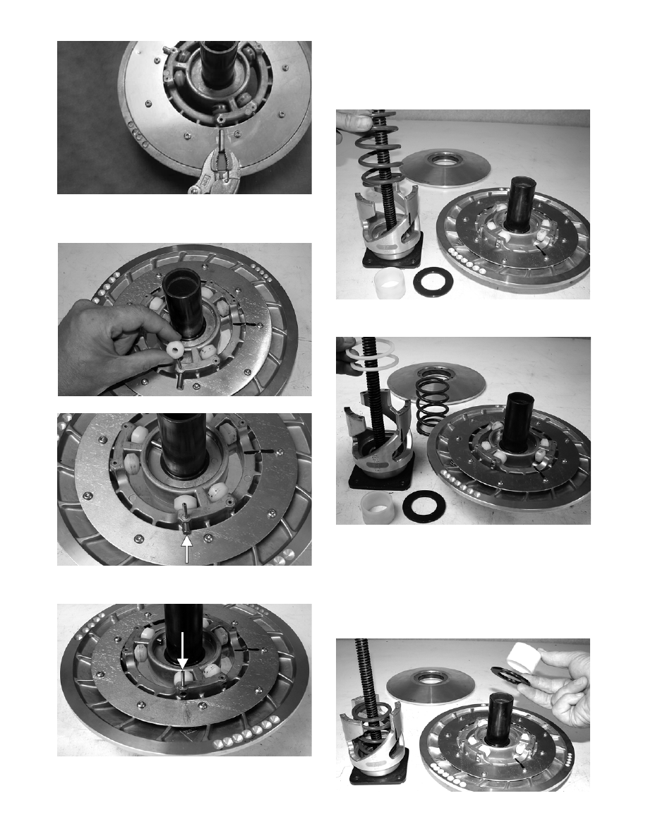
3. Place the new roller into position and tap the roller

pin in far enough to install the spring pin.

CM066

CM067A

4. Tap the spring pin back into place.

CM068A

ASSEMBLING

1. Place the torque bracket onto the Driven Pulley

Compressor (p/n 0644-444); then place the spring

and plastic washer (spring seat) into position.

CM063

2. Install the spring seats onto the torque bracket.

CM064

„NOTE: Premature wear will result if the plastic
washer is not installed.

3. Noting the alignment marks made during disas-

sembling and with the spring seat and spacer on

the stationary sheave shaft, place the stationary

sheave onto the torque bracket.

CM062

8-33

8

4. Place the spacer (retainer) into position on the sta-

tionary sheave noting the proper location of the

holes from disassembling. 

FS094

5. Noting the alignment marks made during disas-

sembling, place the movable sheave onto the sta-

tionary sheave.

FS093

6. With the pulley in place on the compressor, install

the compressor flange spacer and wing nut; then

compress the driven pulley spring.

CM069

7. Install the torx-head cap screws securing the mov-

able sheave. Tighten to specifications.

CM061

8. Remove the pulley from the compressor.

INSTALLING

1. Set the brake lever lock.

2. Install the alignment washers; then install the

driven pulley on the gear case input shaft. Tighten

to specifications.

CM125A

3. Check drive clutch/driven pulley alignment.

4. Install the drive belt.

„NOTE: For installing drive belt, see Removing/
Installing Drive Belt (ACT Roller Driven Pulley) in
this section.

! CAUTION

It is critical that no less than two 1.5 mm (0.060 in.)
washers are in place on the input shaft when install-
ing the driven pulley. 

8-34

Drive Clutch/

Driven Pulley

(Crossfire/F-Series/M-Series)

CHECKING OFFSET

If premature drive belt wear is experienced or if the

drive belt turns over, parallelism/offset must be

checked. Also, parallelism/offset must be checked

whenever either the drive clutch or driven pulley is

serviced. To check offset, use Clutch Alignment Bar

(p/n 0644-427) for the Crossfire/M-Series or (p/n

0644-496) for the F-Series. To check parallelism, use

Clutch Alignment Bar (p/n 0644-509).

1. Open the side panel and remove the drive belt.

„NOTE: For removing drive belt, see Removing/
Installing Drive Belt (ACT Roller Driven Pulley) in
this section.

2. Install the clutch alignment bar between the drive

clutch sheaves and against the outside edge of the

driven pulley stationary sheave.

3. Allow the alignment bar to rest on the drive clutch

shaft.

„NOTE: The alignment bar must extend beyond
the front edge of the drive clutch.

4. With the bar against the outside edge of the driven

pulley stationary sheave, the bar should just clear

the inside edge of the stationary sheave of the

drive clutch and rest on the stationary shaft. If the

bar does not clear the inside edge or is more than

1.5 mm (0.060 in.) from the inside edge, the offset

must be corrected.

742-044A

CORRECTING OFFSET

1. To correct offset, the driven pulley must be moved

laterally on the output shaft. Remove the cap

screw and washers securing the driven pulley; then

remove the driven pulley.

„NOTE: If the driven pulley is tight on the shaft,
pull the driven pulley off using the Driven Pulley
Puller (p/n 0644-469).

2. To move the driven pulley inward on the shaft,

remove washer(s) as required from behind the pul-

ley.

3. To move the driven pulley outward on the shaft,

add alignment washer(s) as required behind the

driven pulley.

4. Install the driven pulley and secure with a cap

screw and washers. Tighten the cap screw to spec-

ifications.

CHECKING PARALLELISM

1. Check parallelism of the drive clutch/driven pulley

using the alignment bar and reference points X and

Y with the alignment bar against the driven pulley.

Using a calipers or a machinist’s scale, measure X

and Y from the back side of the alignment bar.

Measurement Y must be 1.5 mm ± 1.0 mm (0.060

in. ± 0.040 in.) more than measurement X, but Y

must not exceed measurement X by more than

2.54 mm (0.100 in.).

0742-065

„NOTE: The offset must be correct before check-
ing parallelism.

2. If parallelism is not within specifications, the par-

allelism must be corrected.

DRIVE BELT DEFLECTION

Drive belt length, condition, and deflection are all

important for peak performance. To check and adjust

drive belt deflection, use the following procedure.

1. Turn the engine off; then open the access panel.

2. Make sure the drive belt is sitting at the top of the

driven pulley sheaves.

! CAUTION

Do not allow the driven pulley to “float” on the out-
put shaft. Damage to the driven pulley will occur. 

8-35

8

3. Place a straightedge on top of the drive belt. The

straightedge should reach from the drive clutch to

the top of the driven pulley.

4. Using a stiff ruler centered between the drive

clutch and driven pulley, push down on the drive

belt just enough to remove all slack. Note the

amount of deflection on the ruler at the bottom of

the straightedge. The deflection should be at

31 mm (1 1/4 in.).

741-464A

„NOTE: Push down on the belt with the ruler only
until the bottom of the belt flexes upward; then
read the amount of deflection.

5. To correct drive belt deflection, remove the sheave

adjuster from the pulley, remove or add shim

washers to the adjuster, and install the adjuster.

„NOTE: Adding shim washers will decrease belt
deflection; removing shim washers will increase
belt deflection.

„NOTE: If the drive belt deflection is above specifi-
cations, the snowmobile will bog and lack power at
clutch engagement. For good performance, proper
belt deflection is critical.

6. Close the access panel.

Removing/Installing 

Drive Belt

(ACT Roller Driven Pulley)

1. Turn ignition key to the OFF position and wait for

all moving parts to stop.

2. Set the brake lever lock.

3. Open the left-side access panel; then remove the

belt guard.

4. Remove the cap screw and sheave adjuster from

the end of the driven pulley. Account for and

remove the O-ring and shim washers. Note the ori-

entation of the components for installing purposes.

741-721A

5. With the O-ring and shim washers removed, install

the sheave adjuster and cap screw back into the

driven pulley; then tighten the cap screw until the

sheave adjuster bottoms against the input shaft.

„NOTE: By bottoming the sheave adjuster against
the input shaft, the sheaves of the driven pulley
will spread far enough to allow the removal of the
drive belt.

6. Remove the drive belt from the drive clutch and

driven pulley.

7. Place the drive belt (so the part number can be

read) between the sheaves of the drive clutch first;

then between the sheaves of the driven pulley.

8. Place the shim washers and O-ring (as noted in

removing) onto the sheave adjuster; then install

the cap screw and the sheave adjuster back into the

driven pulley. Tighten the cap screw to specifica-

tions.

9. Install the belt guard; then close the left-side

access panel.

10. Release the brake lever lock.

Drive Train/Brake Disc 

(Standard w/Reverse)

DISASSEMBLING

1. Remove the chain-case drain plug located on the

lower back side of the chain case inside the tunnel

and drain the chain case lubricant.

2. Disconnect the battery cables. Remove the battery

and battery tray.

3. Open the belt guard and remove the drive belt.

! WARNING

Never operate the snowmobile without the belt
guard/access panel secured in place.


Content   ..  101  102  103  104   ..