Snowmobile Arctic Cat 2-Stroke (2007 year). Manual - part 102


  Index      Snowmobiles / ATV     Snowmobile Arctic Cat 2-Stroke - service manual 2007 year


Search            


Content   ..  100  101  102  103   ..


Snowmobile Arctic Cat 2-Stroke (2007 year). Manual - part 102


8-28

4. Install the driven pulley and secure with a cap

screw and washers. Tighten the cap screw to spec-

ifications.

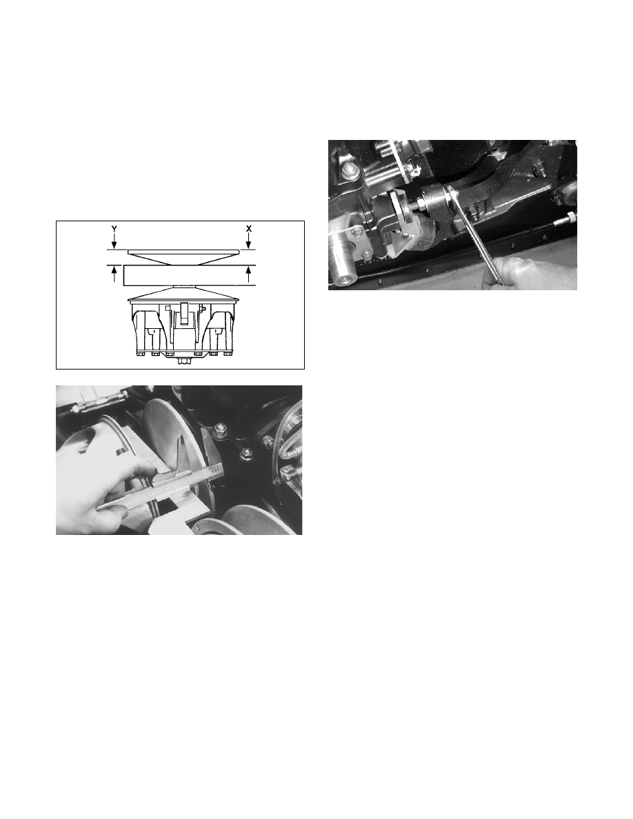
CHECKING PARALLELISM

1. Check parallelism of the drive clutch/driven pulley

using the alignment bar and reference points X and

Y with the alignment bar against the driven pulley

at points A and B. Using a calipers or a machinist's

scale, measure X and Y from the back side of the

alignment bar. Measurements X and Y must be

equal or measurement Y must be more than mea-

surement X, but Y must not exceed measurement

X by more than 1.6 mm (0.062 in.).

733-912A

AF041

„NOTE: The offset must be correct before check-
ing parallelism.

2. If parallelism is not within specifications, the par-

allelism must be corrected.

CORRECTING PARALLELISM 
(Torque Bumper w/Bearing 

Support Bracket)

1. To correct parallelism, minor adjustments can be

made by adjusting the torque bumper on the left-

rear engine mount.

A. Loosen the cap screws and nuts securing the

engine mounting brackets to the front end.

B. Using the jam nuts on the torque bumper, adjust

parallelism and periodically check the parallel-

ism. When the parallelism is correct, tighten the

cap screws and nuts securing the engine mount-

ing brackets to the front end; then tighten the

torque bumper jam nuts allowing 1.5 mm

(0.060 in.) clearance between the torque

bumper and the engine.

AN610D

2. Recheck both offset and parallelism to ensure

accuracy and make further adjustments as neces-

sary.

„NOTE: After parallelism and offset have been
corrected, check for proper drive belt deflection.
This is critical for optimum performance.

CORRECTING PARALLELISM 
(Torque Bumper w/Shims)

1. To correct parallelism, minor adjustments can be

made by removing shims from or installing shims

on the left-rear engine mount.

A. Loosen the cap screws securing the engine

mounting brackets to the front end.

B. Add or remove shims as needed to attain cor-

rect parallelism.

C. When parallelism is correct, secure the engine

mounting brackets to the front end.

2. Recheck both offset and parallelism to ensure accu-

racy and make further adjustments as necessary.

„NOTE: After parallelism and offset have been
corrected, check for proper drive belt deflection.
This is critical for optimum performance.

CORRECTING PARALLELISM 

(Engine Snubber w/Engine Plate)

1. To correct parallelism, minor adjustments can be

made by adjusting the engine snubber on the left-

rear engine mount.

A. Loosen the cap screws securing the engine plate

to the engine mounts.

8-29

8

B. Either lengthen or shorten the snubber and peri-

odically check the parallelism measurement.

When the parallelism measurement is correct,

loosen the snubber to allow 1.5 mm (0.060 in.)

clearance between the snubber and the engine;

then lock the jam nuts on the snubber and tighten

the cap screws securing the engine plate.

2. Recheck both offset and parallelism to ensure accu-

racy and make further adjustments as necessary.

„NOTE: After parallelism and offset have been
corrected, check for proper drive belt deflection.
This is critical for optimum performance.

DRIVE BELT DEFLECTION

Drive belt length, condition, and deflection are all

important for peak performance. To check and adjust

drive belt deflection, use the following procedure.

1. Turn the engine off; then open the belt guard.

2. Make sure the drive belt is sitting at the top of the

driven pulley sheaves.

3. Place a straightedge on top of the drive belt. The

straightedge should reach from the drive clutch to

the top of the driven pulley.

4. Using a stiff ruler centered between the drive

clutch and driven pulley, push down on the drive

belt just enough to remove all slack. Note the

amount of deflection on the ruler at the bottom of

the straightedge. The deflection should be within

the range of 25-31 mm (1-1 1/4 in.).

„NOTE: Push down on the belt with the ruler only
until the bottom of the belt flexes upward; then
read the amount of deflection.

5. To correct drive belt deflection, washers can be

removed or added between the stationary and

movable sheaves of the driven pulley.

„NOTE: If the drive belt deflection is above specifi-
cations, the snowmobile will bog and lack power at
clutch engagement. For good performance, proper
belt deflection is critical.

6. Secure the belt guard.

ACT Roller Driven Pulley


(Crossfire/F-Series/M-Series)

REMOVING

1. Remove the drive belt.

„NOTE: For removing drive belt, see Removing/
Installing Drive Belt (ACT Roller Driven Pulley) in
this section.

2. Using a 9/16-in. socket and extension, remove the

cap screw securing the driven pulley to the driven

shaft.

3. Slide the driven pulley off the driven shaft.

„NOTE: Account for and remove any alignment
washers. These washers must be used during
installing.

DISASSEMBLING

1. Prior to disassembling, mark the driven pulley

sheaves and torque bracket.

CM060

2.  Place the driven pulley on the Driven Pulley Com-

pressor (p/n 0644-444); then install the compres-

sor flange spacer and wing nut and compress the

driven pulley spring.

FS090

3. Remove the torx-head cap screws securing the

movable sheave to the pulley.

CM061

8-30

„NOTE: To loosen the torx-head cap screws, it
may be necessary to insert a torx-bit and strike
each screw with a hammer.

4. Release the compression of the spring by remov-

ing the wing nut; then remove the movable sheave.

Account for the spacer (retainer). 


FS093

FS094

„NOTE: Note the location of the holes in the
spacer for assembling purposes.

5. Remove the stationary sheave; then remove the

plastic washer (spring seat) and the spacer.

CM062

6. Remove the spring.

CM063

7. Remove the remaining spring seats.

CM064

„NOTE: Premature wear will result if the plastic
washer is not installed during assembling.

CLEANING AND INSPECTING

„NOTE: Whenever a part is worn excessively,
cracked, or damaged in any way, replacement is
necessary.

1. Using parts-cleaning solvent, wash grease, drive

belt dust, and foreign matter off all components.

2. Inspect the rollers for damage, cracks, or wear.

3. Inspect the sheaves for any gouges, cracks, or

other damage. Also, inspect threaded areas of

sheaves for damaged or stripped threads.

4. Inspect the torque bracket for cracks or damage.

The ramp portions of the bracket must be free of

gouges and damage. Minor scratches may be

repaired using #320 grit wet-or-dry sandpaper.

! CAUTION

Do not use steel wool or a wire brush to clean driven
pulley components. A wire brush or steel wool will
cause the sheaves to be gouged (thus, the drive belt
may not slide properly between sheaves). Decreased
performance and possible accelerated drive belt
wear will result.

8-31

8

5. Inspect spring for distortion, crystallization, or

breaks.

6. Inspect the rollers, pins, and spring mounting

holes for cracks, damage, or wear.

7. Inspect the cover and movable sheave bearings for

wear. For each respective bearing, measure the

outside diameter of the shaft and the inside diame-

ter of the bearing. Compare the readings. Clear-

ance between the shaft and the respective bearing

must not exceed 0.5 mm (0.020 in.). If the clear-

ance exceeds the specification, the bearing must

be replaced.

„NOTE: The movable sheave bearing is a non-ser-
viceable component.

FS121

FS122

FS123

REPLACING TORQUE BRACKET 
BEARING/COVER BEARING

1. Remove the snap ring.

2. Using a suitable driving tool, drive the bearing out.

3. Install the new bearing; then secure with the snap

ring.

REPLACING ROLLERS

1. Drive the spring pins through the stationary sheave

until there is enough room to drive out the cam

roller pin.

FS101

2. Using an Allen wrench and a flat-blade screw-

driver, press the roller pin out of the stationary

sheave.

CM065

„NOTE: Once the roller pin is exposed, it may be
necessary to use a pair of vise-grips to remove the
pin.

! WARNING

Always wear safety glasses when using the bearing
driver.

! CAUTION

Care must be taken not to damage the driven pulley
shaft. 


Content   ..  100  101  102  103   ..