Snowmobile Arctic Cat 2-Stroke (2007 year). Manual - part 86


  Index      Snowmobiles / ATV     Snowmobile Arctic Cat 2-Stroke - service manual 2007 year


Search            


Content   ..  84  85  86  87   ..


Snowmobile Arctic Cat 2-Stroke (2007 year). Manual - part 86


7-30

1. Secure the steering tie rod in the centered posi-

tion.

2. Loosen both spindle tie rod jam nuts on the

same side as the ski to be aligned.

3. Using a wrench on the spindle tie rod “flats,”

rotate the spindle tie rod until recommended

specification is attained.

4. Apply blue Loctite #243 to each jam nut thread

area; then lock the jam nuts against the spindle

tie rod. Tighten to 1.7-2.1 kg-m (12-15 ft-lb).

„ NOTE: Repeat this procedure on each side (if
necessary) until ski toe-out is within specification.
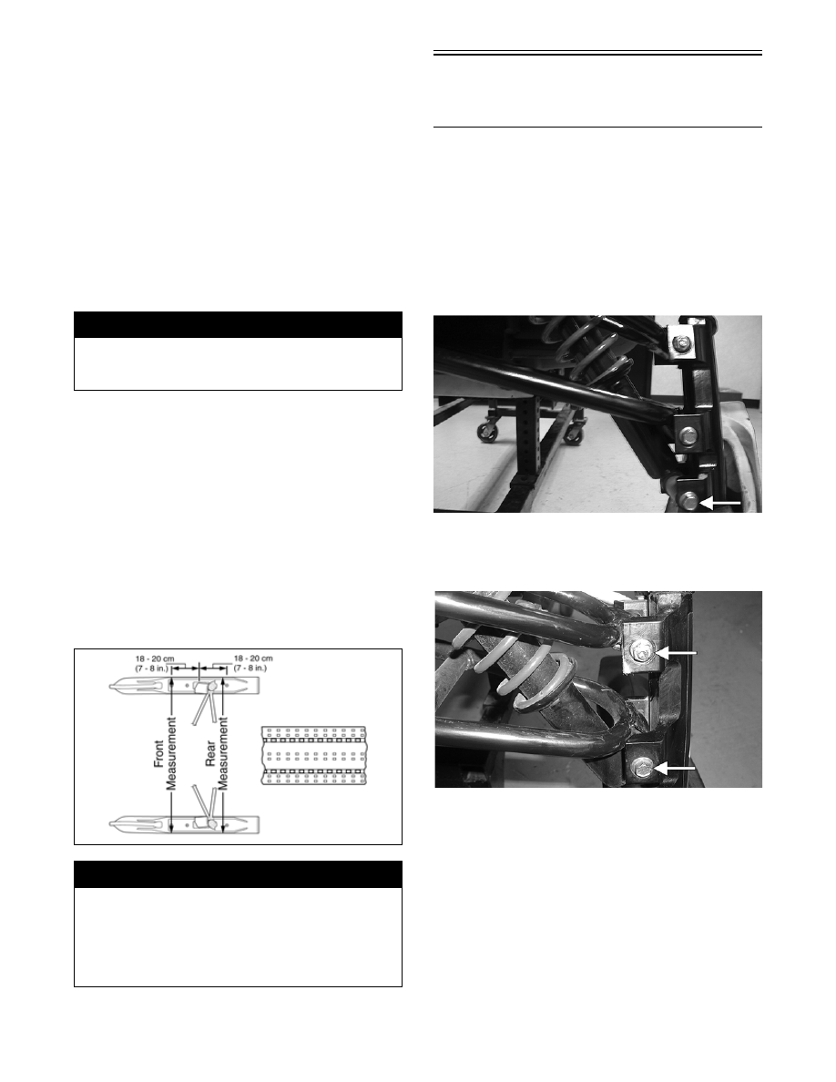
VERIFYING

1. With the handlebar in the straight-ahead position,

verify ski alignment by measuring across from the

outside edge of the left-side wear bar bolts to the

outside edge of the right-side wear bar bolts (with-

out using the straightedge) in two places: approxi-

mately 18-20 cm (7-8 in.)  in  front  of  the  spindle

and 18-20 cm (7-8 in.) behind the spindle.

2. The measurement from in front of the spindle to

the outer edge of the wear bar bolts (without using

the straightedge) must not exceed the rear mea-

surement by more than 1.6-6.4 mm (1/16-1/4 in.)

toe-out.

0734-408

Front

Suspension Arms 

(Bearcat/Panther/Z)

REMOVING

1. Remove the expansion chamber if necessary.

2. Position the front of the snowmobile up onto a

safety stand.

3. Remove the lock nuts and cap screws securing the

shock absorber; then remove the shock absorber.

Account for all mounting hardware.

FS084C

4. Remove the cap screws and lock nuts securing the

spindle to the front suspension arms. Account for

all mounting hardware.

FS086A

5. On models with a sway bar, remove the cap screw

and lock nut securing the sway bar link to the front

suspension arm.

6. Remove the screws and lock nut securing the skid

plate; then remove the skid plate.

! WARNING

Neglecting to lock the tie rod by tightening the jam
nuts may cause loss of snowmobile control and pos-
sible personal injury.

! WARNING

The measurement taken in front of the spindle must
never be less than the measurement taken behind
the spindle or poor handling will be experienced.
Neglecting to lock the tie rod by tightening the jam
nuts may cause loss of snowmobile control and pos-
sible personal injury.

7-31

7

AL144D

7. If applicable, remove the self-tapping screws

securing the steering boot to the front end.

8. Remove the cap screws and lock nuts securing the

suspension arms to the front end; then remove the

arms.

INSPECTING

„NOTE: Whenever a part is worn excessively,
cracked, or damaged in any way, replacement is
necessary.

1. Inspect the arm welded areas for cracks or any

signs of deterioration.

2. Inspect the bearings and axles for wear or damage.

3. Inspect the arm tubing for signs of twisting or

bending.

INSTALLING

1. Place the suspension arms into position on the

front end and secure with the cap screws (coated

with green Loctite #609) and lock nuts. Tighten

the upper arm cap screw and lock nut to specifica-

tions. Tighten the lower arm cap screw and lock

nut to specifications.

2. If applicable, place the steering boot into position

on the front end. Secure with the self-tapping

screws.

3. Install the skid plate and secure with the screws,

washer, and lock nut.

AL144D

4. If applicable, place the sway bar link into position

on the suspension arm and secure with cap screw

and lock nut. Tighten securely.

5. Accounting for mounting hardware, install the

spindle onto the suspension arm with the cap

screws and lock washers.

FS086A

6. Place the shock absorber into position and secure

with two cap screws, washers, axles, spacers,

sleeves, and lock nuts. Tighten to specifications.

AL157D

FS084C

7. Install and secure the expansion chamber if

removed.

7-32

Front

Suspension Arms

(Crossfire/M-Series)

REMOVING

1. Position the front of the snowmobile up onto a

safety stand.

2. Remove the ski.

3. Remove the Allen-head cap screw securing the tie

rod to the steering arm.

4. Remove the lock nuts and cap screws securing the

shock absorber; then remove the shock absorber.

Account for all mounting hardware.

FS017

5. Remove the cap screws and lock nuts securing the

spindle to the front suspension arms. Account for

all mounting hardware.

FS019

FS018

6. Remove the cap screw and lock nut securing the

sway bar link to the front suspension arm.

FC216

7. Remove the three torx-head screws securing the

air silencer to the front bumper.

FC217

8. Remove the two torx-head cap screws securing the

front bumper to the side belly pans. 

7-33

7

FC218

9. Remove the two hairpin clips and hood pins secur-

ing the hood to the front bumper.

FC219

FC220

10. Remove the remaining eight torx-head screws

securing the front bumper. Account for the center

belly pan screen.

FC221

FC222

11. Remove the cap screw and lock nut securing the

upper arm. Account for the washer.

FC223

12. Remove the 10 torx-head screws securing the cen-

ter belly pan to the frame. Note the location of the

different-length screws for installing purposes. 

FC224

! CAUTION

To avoid damage to the hood, carefully close it and
rest it on the handlebar.


Content   ..  84  85  86  87   ..