Snowmobile Arctic Cat 2-Stroke (2007 year). Manual - part 84


  Index      Snowmobiles / ATV     Snowmobile Arctic Cat 2-Stroke - service manual 2007 year


Search            


Content   ..  82  83  84  85   ..


Snowmobile Arctic Cat 2-Stroke (2007 year). Manual - part 84


7-22

4. Secure the spindle in a vise. Rotate the spindle

clockwise and counterclockwise. The movement

should be smooth and free. If the spindle move-

ment is rough or binding, grease the spindle with a

good low-temperature grease. Rotate the spindle.

If the movement remains rough, replace the spin-

dle. 

„NOTE: When greasing the spindle, use enough
grease so that it can be seen coming out at both
the top and bottom of the spindle. 

5. Inspect the spindle axle and bearings for wear,

damage, or loose fit. Replace the bearings as a set. 

„NOTE: Replacing the ski bolt bushings is diffi-
cult. The existing bushings will be damaged during
removal. Be careful, however, not to damage the
spindle when removing the bearing. Press the new
bushings into the spindle. 

INSTALLING

1. Insert the spindle shaft into the spindle making

sure the two washers are correctly positioned. 

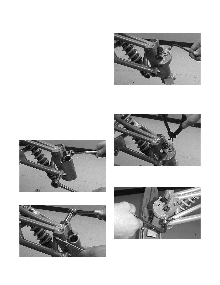
2. Place the upper and lower suspension arm ends

with bushings in position into the spindle. Secure

with cap screws (threads coated with green Loctite

#609) and lock nuts. Tighten the lower lock nut to

specifications.

FC214

3. Tighten the upper lock nut to specifications.

FC213

4. Install the cap onto the spindle; then place the

steering arm tie rod into position on the spindle.

Secure with the Allen-head cap screw coated with

green Loctite #609. Tighten to specifications.

FC211

5. Install the snap ring noting the correct direction of

the snap ring. 

„NOTE: The sharp side of the snap ring should
be directed away from the spindle arm.

FC210

6. Place the tie rod into position on the spindle arm.

Secure with the Allen-head cap screw coated with

green Loctite #609. Tighten to specifications.

FC209

7. Place the shock absorber into position on the spin-

dle. Secure with the cap screw and lock nut.

Tighten to specifications.

8. Install the ski.

7-23

7

9. Remove the safety stand from beneath the front

end.

Spindle

(F-Series)

REMOVING

1. Position the front of the snowmobile up on a

safety stand.

2. Remove the ski.

3. Remove the tie rod cap and lock nut securing the

tie-rod ball joint to the spindle; then remove the

ball joint from the spindle.

„ NOTE: Note whether the tie rod is installed on
the top side or on the bottom side of the spindle
arm for installing purposes.

4. Remove the cap and snap ring from the top of

the spindle; then remove the cap screw securing

the spindle arm to the spindle. Remove the spin-

dle arm and account for and note the number of

thrust washers for installing purposes.

ZJ172

ZJ177

„ NOTE: The cap screw must be removed to
remove the spindle from the spindle housing.

5. Using a soft hammer and a suitable driving tool,

drive the spindle out of the spindle housing.

6. Remove the lock nut and cap screw securing the

shock absorber to the spindle. Account for all

mounting hardware.

ZJ173A

7. Remove the four torx-head cap screws securing

the lower A-arm bearing cap to the spindle; then

remove the cap and lower arm from the spindle.

ZJ174A

8. Remove the cap screw and lock nut securing the

spindle to the upper suspension arm. Account

for all mounting hardware.

INSPECTING

„ NOTE: Whenever a part is worn excessively,
cracked, or damaged in any way, replacement is
necessary.

1. Inspect the spindle for excessive wear, cracks,

bends, or imperfections.

2. Inspect all welds for cracking.

3. Inspect the suspension arm bushings and axle

area for wear.

4. Secure the spindle in a vise. Rotate the spindle

clockwise and counterclockwise. The move-

ment should be smooth and free. If the spindle

movement is rough or binding, grease the spin-

dle with a good low-temperature grease. Rotate

the spindle. If the movement remains rough,

replace the spindle.

7-24

„ NOTE: When greasing the spindle, use enough
grease so it can be seen coming out at both the
top and bottom of the spindle.

5. Inspect the spindle axle and bearings for wear,

damage, or loose fit. Replace the bearings as a

set.

6. Inspect the tie-rod ball joint in place. If damage,

wear, or unusual bends are noted, loosen the jam

nut; then remove the ball joint from the tie rod.

„ NOTE: Replacing the ski bolt bushings is diffi-
cult. The existing bushings will be damaged during
removal. Be careful, however, not to damage the
spindle when removing the bushing. Press the
new bushings into the spindle.

INSTALLING

1. Place the upper arm end (with axle) into position

in the spindle. Secure with cap screw and lock

nut. Tighten only until snug.

2. Install new split bearings onto the shaft of the

lower A-arm; then using a suitable pliers, evenly

compress the bearing until it is properly fitted to

the shaft.

ZJ175A

„ NOTE: The split bearings cannot be reused;
they must be replaced with new ones.

3. Position the spindle into the lower A-arm; then

install the bearing cap and secure the cap to the

spindle with the four torx-head cap screws.

Tighten to specifications.

ZJ174A

4. With the shock sleeve in place, align the lower

shock eyelet with the mounting hole in the spin-

dle; then secure with the cap screw, optional

washers, and lock nut. Tighten to specifications.

ZJ173A

5. At this point, tighten the lock nut (from step 1)

to specifications.

ZJ173B

6. Install the spindle into the spindle housing; then

with the correct number of thrust washers (as

noted in removing and with the space (A) in the

splines of the spindle aligned with the slot (B) in

the spindle arm, install the spindle arm.

7-25

7

ZJ177

ZJ295A

7. Install the cap screw securing the spindle arm to

the spindle; then tighten to specifications.

ZJ176A

8. Install the snap ring and spindle cap.

ZJ172

9. Place the steering tie-rod ball joint into position

(threads coated with Loctite #609) on the spin-

dle arm as noted during removing and secure

with a lock nut. Tighten to specifications; then

install the tie rod cap.

10. Install the ski.

11. Remove the safety stand from beneath the front

end.

Steering Tie Rod


(Bearcat/Panther/Z)

REMOVING

1. Remove the screws securing the skid plate; then

remove the skid plate.

„NOTE: The front machine screw on some mod-
els is secured with a washer and lock nut.

AL144D

2. Remove the cotter pins, cap screws, and slotted

nuts securing the steering tie rod to the steering

post and steering arm; then remove the tie-rod

assembly.

AL089

3. Loosen the jam nuts securing the ball joints to the

steering tie rod; then remove the ball joints.


Content   ..  82  83  84  85   ..