Snowmobile Arctic Cat 2-Stroke (2007 year). Manual - part 66
4-38
INSTALLING
1. In turn on each front union bolt, install a gasket,
check valve, and gasket; then install on the oil-
injection pump.
2. Place the gasket and oil-injection pump near the
engine; then install the lower union bolt through a
gasket, check valve, and gasket.
3. Position the oil-injection pump on the engine mak-
ing sure the oil-injection pump gear is correctly
aligned with the oil-injection pump drive gear.
4. Secure the pump with two screws, lock washers (if
applicable), and washers (if applicable). Tighten
screws to 1.1 kg-m (8 ft-lb).
5. Connect the two oil-delivery hoses to the adapter
plates. Secure with clamps.
6. Connect the oil-injection cable/control rod to the
pump and secure.
7. Connect the oil-supply hose to the oil-injection
pump inlet fitting. Secure with the clamp.
8. Bleed the oil-injection system (see Bleeding Oil-
Injection System in this sub-section).
9. Check the oil-injection system synchronization
(see Synchronizing Oil-Injection Pump in this sub-
section). Tighten the jam nuts securely.
NOTE: On EFI models to install the exhaust sys-
tem and the air silencer, see Section 2.
10. Install the carburetors/throttle bodies.
11. On carbureted models, turn the shut-off valve to
the OPEN position.
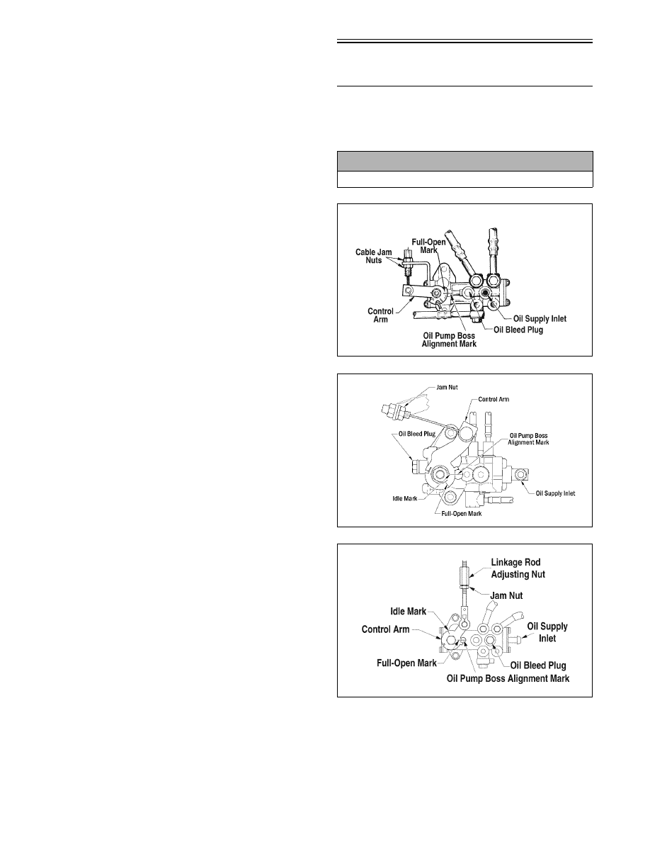
Synchronizing
Oil-Injection Pump
NOTE: On certain models, the oil pump cable
adjuster is located at the juncture of the throttle
cable.
728-713A
742-331A
738-338C
! CAUTION
Use a 100:1 fuel mixture for the following procedure.
370/570 cc
500 cc
600 cc