Snowmobile Arctic Cat 2-Stroke (2007 year). Manual - part 51
3-7
3
FC129
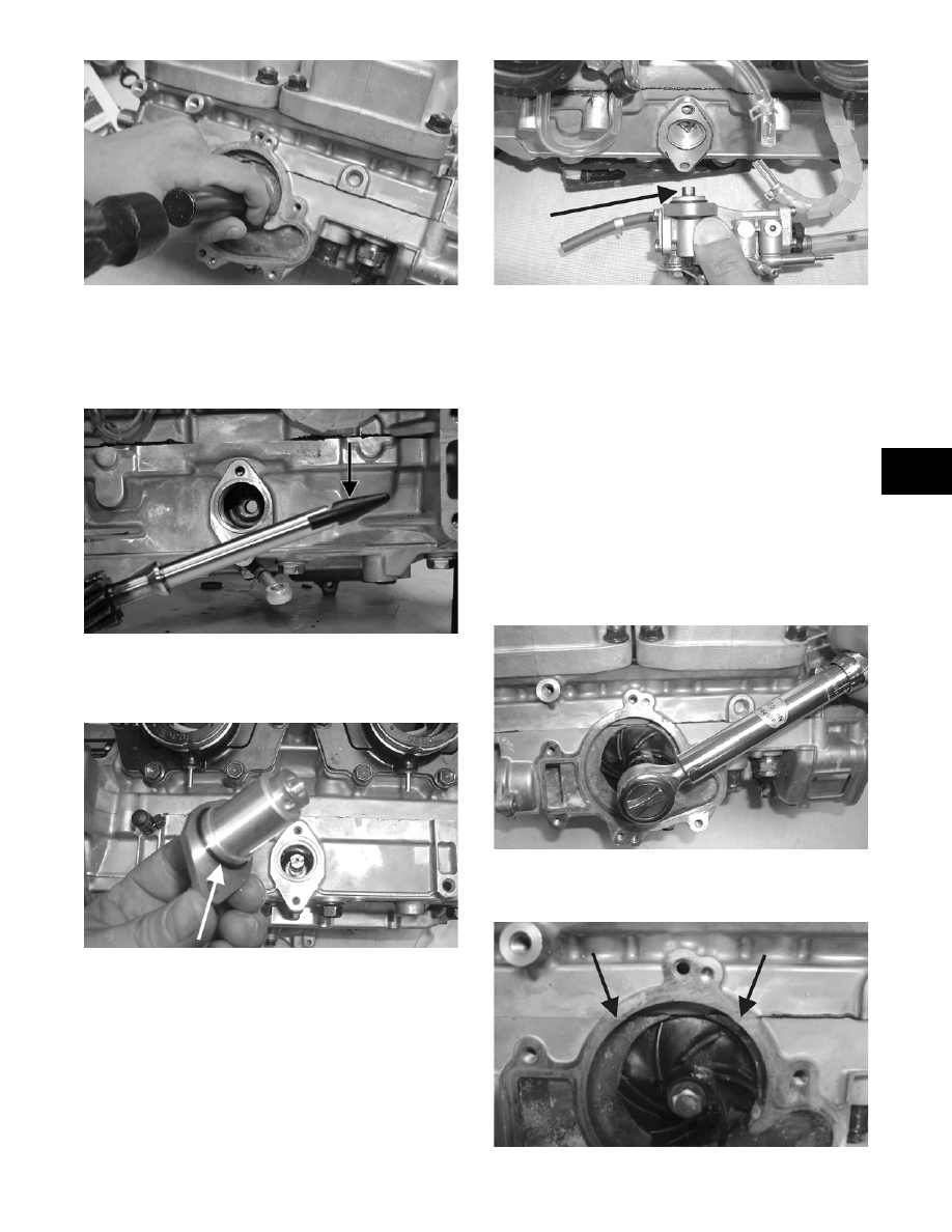
6. Apply a light coat of grease to the sealing surface
of the oil-injection pump driveshaft; then install
Oil Seal Protector Tool (p/n 0644-219) at the end
of the shaft. Twist the shaft as it is pushed through
the oil and water pump seals; then remove the tool.
FS233A
7. Position the shim on the oil pump end of the shaft;
then with the O-ring installed on the retainer,
install the oil-injection pump retainer.
FC130A
8. With the O-ring in place on the oil-injection pump,
align the pump with the shaft; then install the
pump. Secure with two cap screws (coated with
blue Loctite #243). Tighten the two cap screws to
0.7 kg-m (5 ft-lb).
FC131A
NOTE: After the oil pump has been secured,
assure that the oil hoses from the pump and intake
flanges are routed properly.
9. Place the lower check valve into position; then
secure with the gaskets and union cap screw.
Tighten securely.
NOTE: When installing the lower check valve,
assure that the gaskets are installed on each side
of the valve.
10. Place the impeller into position and secure with a
cap screw and washer. Be sure the rubber side of
the washer is directed towards the impeller. Apply
blue Loctite #243 to the threads of the cap screw
and tighten to 0.8-1.2 kg-m (6-9 ft-lb).
FC132
11. Apply sealant to the crankcase seam; then install
the alignment pins into the crankcase (if removed).
FC133A