Snowmobile Arctic Cat 2-Stroke (2007 year). Manual - part 20
2-66
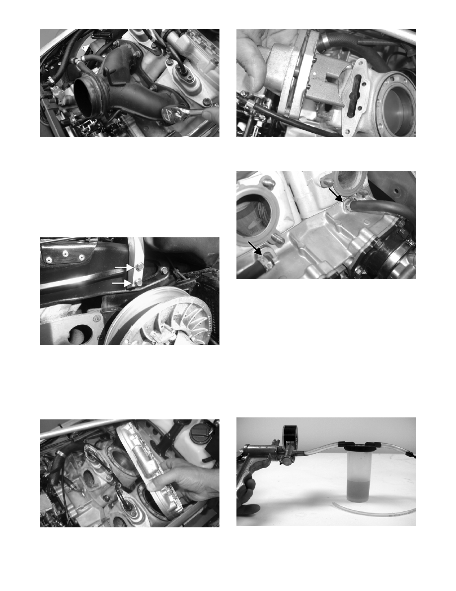
CM035
2. Drain the engine coolant (see Liquid Cooling Sys-
tem - Section 3).
3. Remove the cap screws and the lock nuts securing
the side-plate brace to the chassis; then remove the
brace.
NOTE: The cap screws securing the steering
support to the chassis must be removed to remove
the side-plate brace.
CM004B
4. Remove the coolant hose and breather hose con-
nected to the cylinder head.
5. Remove the twelve 10 mm cap screws and two 8
mm cap screws (500 cc) securing the cylinder
head; then remove the cylinder head. Account for
the O-rings.
FC060
6. On the 600 cc, remove the APV’s from the cylin-
der.
FC056
7. Disconnect the two coolant hoses located beneath
the exhaust ports on the cylinders.
FC050A
NOTE: At this point, remove all loose hardware to
avoid any falling down into the chassis.
8. Remove the residual coolant from the cylinder/
crankcase water jacket.
NOTE: After draining the coolant, approximately
1.75 fluid oz of coolant will remain on both the
MAG-side and PTO-side. To remove the residual
coolant, use the following procedure.
a. Using Vacuum Pump (p/n 0644-131), or a suit-
able substitute, rig the pump to 3/16 in. outside
diameter hose.
FC058
b. In turn on each fitting of the crankcase, run the
vacuum pump to purge the cylinder/crankcase
water jacket of the residual coolant.