Snowmobile Arctic Cat 2-Stroke (2007 year). Manual - part 19
2-62
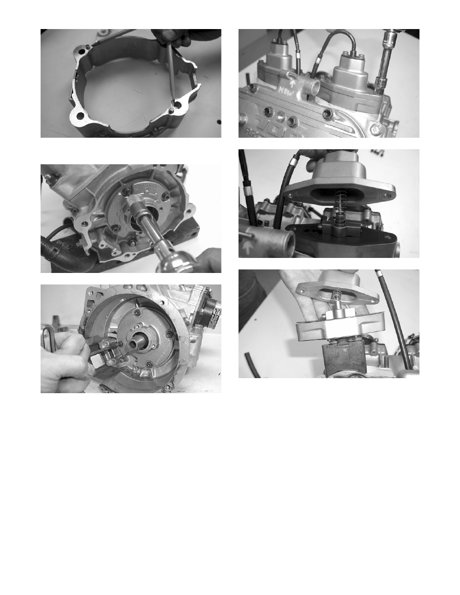
FC020
7. Remove the stator plate from the engine.
FC021
FC065
NOTE: The stator plate screws had Loctite
applied to the threads during assembly. Using an
impact driver, apply a sharp blow to the head of
each screw to break the Loctite loose before
removal.
8. On the 600 cc, remove the cap screws securing the
APV assemblies to the cylinders; then remove the
APV assemblies and set them aside.
NOTE: Note that the APV exhaust valves and
gaskets are directional for assembling purposes.
NOTE: The following photographs are for clarity
purposes only. The models may vary slightly.
FC023
FC024
FC025
9. Remove the spark plugs.
10. Remove the cap screws with O-rings securing the
cylinder head; then separate from the cylinders.
Account for the O-rings.
11. Remove the oil-injection hose from each cylinder
and the crankcase nozzle.